NISSAN PATROL 2004 Electronic Repair Manual
Manufacturer: NISSAN, Model Year: 2004, Model line: PATROL, Model: NISSAN PATROL 2004Pages: 579, PDF Size: 26.61 MB
Page 291 of 579
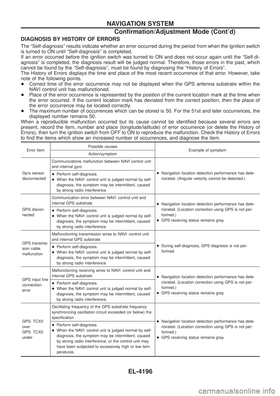
DIAGNOSIS BY HISTORY OF ERRORS
The ªSelf-diagnosisº results indicate whether an error occurred during the period from when the ignition switch
is turned to ON until ªSelf-diagnosisº is completed.
If an error occurred before the ignition switch was turned to ON and does not occur again until the ªSelf-di-
agnosisº is completed, the diagnosis result will be judged normal. Therefore, those errors in the past, which
cannot be found by the ªSelf-diagnosisº, must be found by diagnosing the ªHistory of Errorsº.
The History of Errors displays the time and place of the most recent occurrence of that error. However, take
note of the following points.
+Correct time of the error occurrence may not be displayed when the GPS antenna substrate within the
NAVI control unit has malfunctioned.
+ Place of the error occurrence is represented by the position of the current location mark at the time when
the error occurred. If the current location mark has deviated from the correct position, then the place of
the error occurrence may be located correctly.
+ The maximum number of occurrences which can be stored is 50. For the 51st and later occurrences, the
displayed number remains 50.
When a reproducible malfunction occurred but its cause cannot be identi®ed because several errors are
present, record the item, number and place (longitude/latitude) of error occurrence (or delete the History of
Errors), then turn the ignition switch from OFF to ON to reproduce the malfunction. Check the History of Errors
to ®nd the items which show an increased number of occurrences, and diagnose the item.
Error item Possible causes
Example of symptom
Action/symptom
Gyro sensor
disconnected Communications malfunction between NAVI control unit
and internal gyro
+Navigation location detection performance has dete-
riorated. (Angular velocity cannot be detected.)
+
Perform self-diagnosis.
+ When the NAVI control unit is judged normal by self-
diagnosis, the symptom may be intermittent, caused
by strong radio interference.
GPS discon-
nected Communication error between NAVI control unit and
internal GPS substrate
+Navigation location detection performance has dete-
riorated. (Location correction using GPS is not per-
formed.)
+ GPS receiving status remains gray.
+
Perform self-diagnosis.
+ When the NAVI control unit is judged normal by self-
diagnosis, the symptom may be intermittent, caused
by strong radio interference.
GPS transmis-
sion cable
malfunction Malfunctioning transmission wires to NAVI control unit
and internal GPS substrate
+During self-diagnosis, GPS diagnosis is not per-
formed.
+
Perform self-diagnosis.
+ When the NAVI control unit is judged normal by self-
diagnosis, the symptom may be intermittent, caused
by strong radio interference.
GPS input line
connection
error Malfunctioning receiving wires to NAVI control unit and
internal GPS substrate
+Navigation location detection performance has dete-
riorated. (Location correction using GPS is not per-
formed.)
+ GPS receiving status remains gray.
+
Perform self-diagnosis.
+ When the NAVI control unit is judged normal by self-
diagnosis, the symptom may be intermittent, caused
by strong radio interference.
GPS TCX0
over
GPS TCX0
under Oscillating frequency of the GPS substrate frequency
synchronizing oscillation circuit exceeded (or below) the
speci®cation
+Navigation location detection performance has dete-
riorated. (Location correction using GPS is not per-
formed.)
+ GPS receiving status remains gray.
+
Perform self-diagnosis.
+ When the NAVI control unit is judged normal by self-
diagnosis, the symptom may be intermittent, caused
by strong radio interference, or the control unit may
have been subjected to excessively high or low tem-
peratures.
NAVIGATION SYSTEM
Con®rmation/Adjustment Mode (Cont'd)
EL-4196
Page 292 of 579
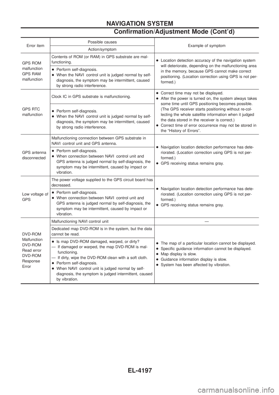
Error itemPossible causes
Example of symptom
Action/symptom
GPS ROM
malfunction
GPS RAM
malfunction Contents of ROM (or RAM) in GPS substrate are mal-
functioning.
+
Location detection accuracy of the navigation system
will deteriorate, depending on the malfunctioning area
in the memory, because GPS cannot make correct
positioning. (Location correction using GPS is not per-
formed.)
+
Perform self-diagnosis.
+ When the NAVI control unit is judged normal by self-
diagnosis, the symptom may be intermittent, caused
by strong radio interference.
GPS RTC
malfunction Clock IC in GPS substrate is malfunctioning.
+
Correct time may not be displayed.
+ After the power is turned on, the system always takes
some time until GPS positioning becomes possible.
(The GPS receiver starts positioning without re-col-
lecting the whole satellite information when it judged
the data stored in the receiver is correct.)
+ Correct time of error occurrence may not be stored in
the ªHistory of Errorsº.
+
Perform self-diagnosis.
+ When the NAVI control unit is judged normal by self-
diagnosis, the symptom may be intermittent, caused
by strong radio interference.
GPS antenna
disconnected Malfunctioning connection between GPS substrate in
NAVI control unit and GPS antenna.
+Navigation location detection performance has dete-
riorated. (Location correction using GPS is not per-
formed.)
+ GPS receiving status remains gray.
+
Perform self-diagnosis.
+ When connection between NAVI control unit and
GPS antenna is judged normal by self-diagnosis, the
symptom may be intermittent, caused by impact or
vibration.
Low voltage of
GPS The power voltage supplied to the GPS circuit board has
decreased.
+Navigation location detection performance has dete-
riorated. (Location correction using GPS is not per-
formed.)
+ GPS receiving status remains gray.
+
Perform self-diagnosis.
+ When connection between NAVI control unit and
GPS antenna is judged normal by self-diagnosis, the
symptom may be intermittent, caused by impact or
vibration.
DVD-ROM
Malfunction
DVD-ROM
Read error
DVD-ROM
Response
Error Malfunctioning NAVI control unit Ð
Dedicated map DVD-ROM is in the system, but the data
cannot be read.
+The map of a particular location cannot be displayed.
+ Speci®c guidance information cannot be displayed.
+ Map display is slow.
+ Guidance information display is slow.
+ System has been affected by vibration.
+
Is map DVD-ROM damaged, warped, or dirty?
Ð If damaged or warped, the map DVD-ROM is mal- functioning.
Ð If dirty, wipe the DVD-ROM clean with a soft cloth.
+ Perform self-diagnosis.
+ When NAVI control unit is judged normal by self-
diagnosis, the symptom is judged intermittent, caused
by vibration.
NAVIGATION SYSTEM
Con®rmation/Adjustment Mode (Cont'd)
EL-4197
Page 293 of 579
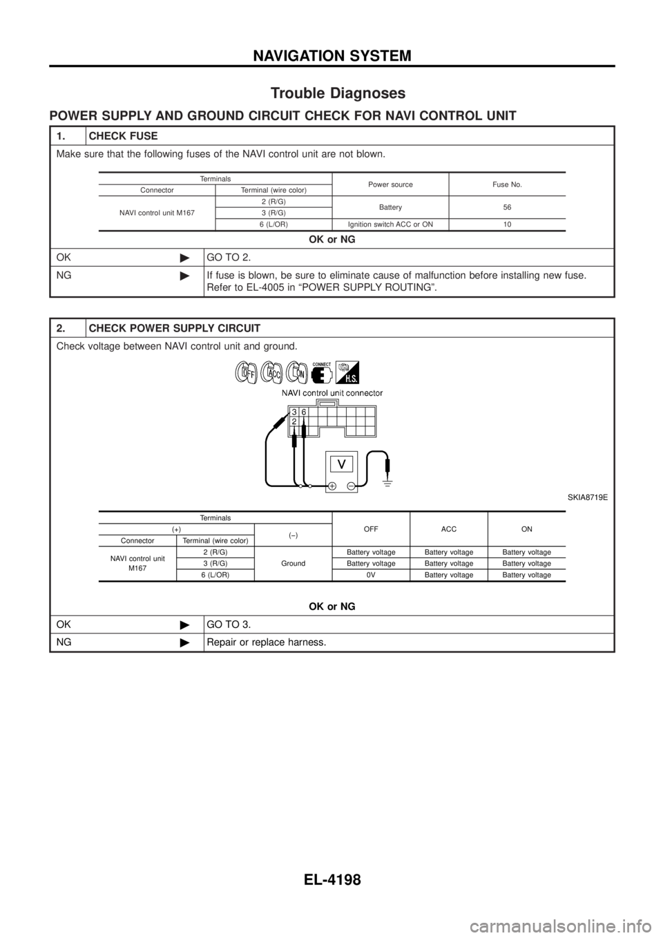
Trouble Diagnoses
POWER SUPPLY AND GROUND CIRCUIT CHECK FOR NAVI CONTROL UNIT
1. CHECK FUSE
Make sure that the following fuses of the NAVI control unit are not blown.OK or NG
OK ©GO TO 2.
NG ©If fuse is blown, be sure to eliminate cause of malfunction before installing new fuse.
Refer to EL-4005 in ªPOWER SUPPLY ROUTINGº.
Terminals
Power source Fuse No.
Connector Terminal (wire color)
NAVI control unit M167 2 (R/G)
Battery 56
3 (R/G)
6 (L/OR) Ignition switch ACC or ON 10
2. CHECK POWER SUPPLY CIRCUIT
Check voltage between NAVI control unit and ground.
SKIA8719E
OK or NG
OK ©GO TO 3.
NG ©Repair or replace harness.
Terminals
OFF ACC ON
(+)
(þ)
Connector Terminal (wire color)
NAVI control unit M167 2 (R/G)
GroundBattery voltage Battery voltage Battery voltage
3 (R/G) Battery voltage Battery voltage Battery voltage
6 (L/OR) 0V Battery voltage Battery voltage
NAVIGATION SYSTEM
EL-4198
Page 294 of 579
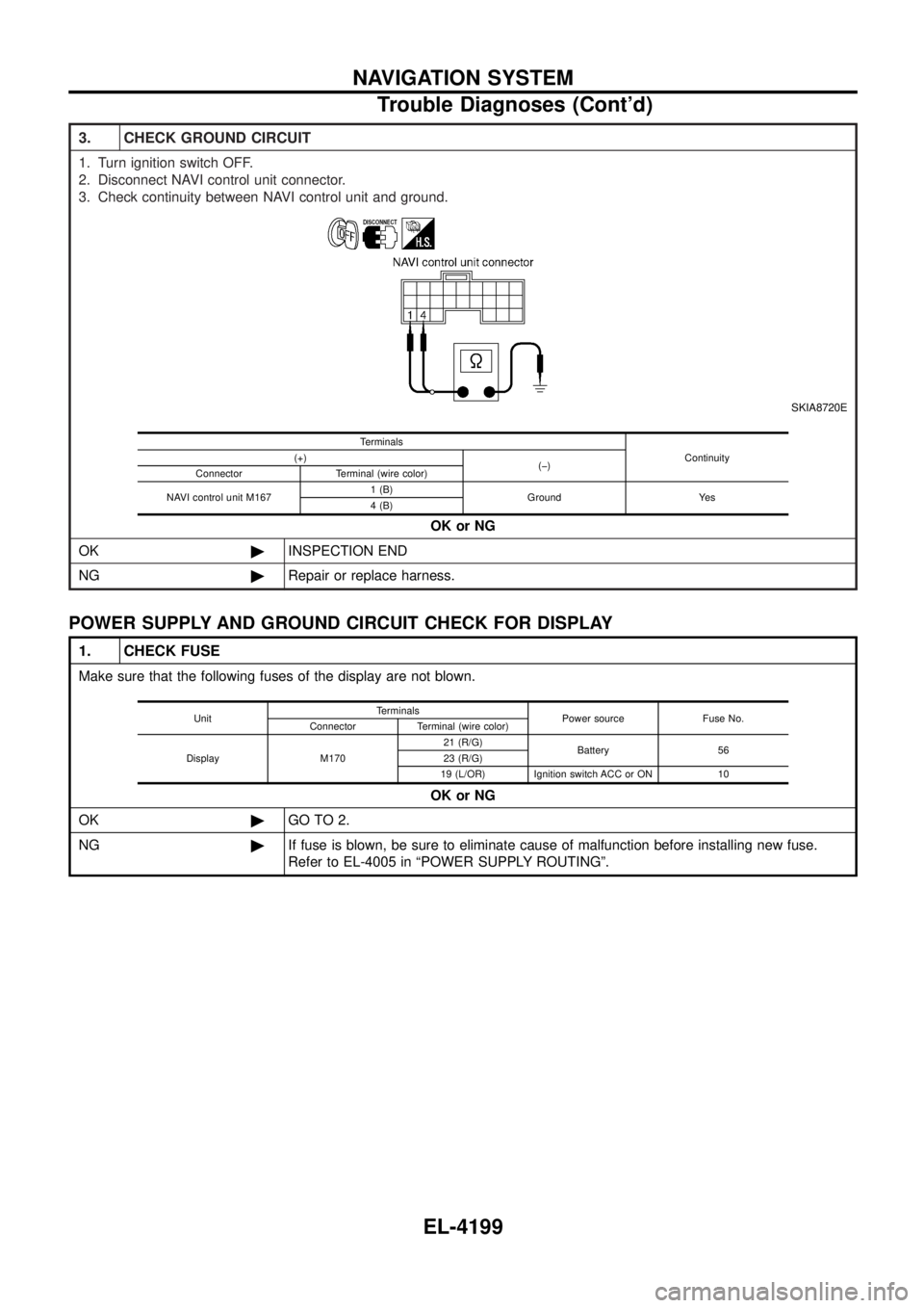
3. CHECK GROUND CIRCUIT
1. Turn ignition switch OFF.
2. Disconnect NAVI control unit connector.
3. Check continuity between NAVI control unit and ground.
SKIA8720E
OK or NG
OK ©INSPECTION END
NG ©Repair or replace harness.
Terminals
Continuity
(+)
(þ)
Connector Terminal (wire color)
NAVI control unit M167 1 (B)
Ground Yes
4 (B)
POWER SUPPLY AND GROUND CIRCUIT CHECK FOR DISPLAY
1. CHECK FUSE
Make sure that the following fuses of the display are not blown.
OK or NG
OK ©GO TO 2.
NG ©If fuse is blown, be sure to eliminate cause of malfunction before installing new fuse.
Refer to EL-4005 in ªPOWER SUPPLY ROUTINGº.
Unit Terminals
Power source Fuse No.
Connector Terminal (wire color)
Display M170 21 (R/G)
Battery 56
23 (R/G)
19 (L/OR) Ignition switch ACC or ON 10
NAVIGATION SYSTEM
Trouble Diagnoses (Cont'd)
EL-4199
Page 295 of 579

2. CHECK POWER SUPPLY CIRCUIT
Check voltage between display and ground.
SKIA9491E
OK or NG
OK ©GO TO 3.
NG ©Repair or replace harness.
Unit Terminals
OFF ACC ON
(+)
(þ)
Connector Terminal (wire
color)
Display M170 21 (R/G)
GroundBattery voltage Battery voltage Battery voltage
23 (R/G) Battery voltage Battery voltage Battery voltage
19 (L/OR) 0V Battery voltage Battery voltage
3. CHECK GROUND CIRCUIT
1. Turn ignition switch OFF.
2. Disconnect display connector.
3. Check continuity between display and ground.
SKIA9492E
OK or NG
OK ©INSPECTION END
NG ©Repair or replace harness.
Unit Terminals
Continuity
(+)
(þ)
Connector Terminal (wire color)
Display M170 22 (B)
Ground Yes
24 (B)
NAVIGATION SYSTEM
Trouble Diagnoses (Cont'd)
EL-4200
Page 296 of 579
![NISSAN PATROL 2004 Electronic Repair Manual POWER SUPPLY AND GROUND CIRCUIT CHECK FOR NAVI SWITCH
1. CHECK FUSE
Check 10A fuse [No. 10, located in fuse block (J/B)].OK or NG
OK ©GO TO 2.
NG ©If fuse is blown, be sure to eliminate cause of mal NISSAN PATROL 2004 Electronic Repair Manual POWER SUPPLY AND GROUND CIRCUIT CHECK FOR NAVI SWITCH
1. CHECK FUSE
Check 10A fuse [No. 10, located in fuse block (J/B)].OK or NG
OK ©GO TO 2.
NG ©If fuse is blown, be sure to eliminate cause of mal](/img/5/57364/w960_57364-295.png)
POWER SUPPLY AND GROUND CIRCUIT CHECK FOR NAVI SWITCH
1. CHECK FUSE
Check 10A fuse [No. 10, located in fuse block (J/B)].OK or NG
OK ©GO TO 2.
NG ©If fuse is blown, be sure to eliminate cause of malfunction before installing new fuse.
Refer to EL-4005 in ªPOWER SUPPLY ROUTINGº.
2. CHECK POWER SUPPLY CIRCUIT
Check voltage between NAVI switch and ground.
SKIA8724E
OK or NG
OK ©GO TO 3.
NG ©Repair or replace harness.
Unit Terminals
OFF ACC ON
(+)
(þ)
Connector Terminal (wire
color)
NAVI switch M169 1 (L/OR) Ground 0V Battery voltage Battery voltage
3. CHECK GROUND CIRCUIT
1. Turn ignition switch OFF.
2. Disconnect NAVI switch connector.
3. Check continuity between NAVI switch harness connector M169 terminal 7 (B) and ground.
SKIA8725E
Continuity should exist. OK or NG
OK ©INSPECTION END
NG ©Repair or replace harness.
NAVIGATION SYSTEM
Trouble Diagnoses (Cont'd)
EL-4201
Page 297 of 579
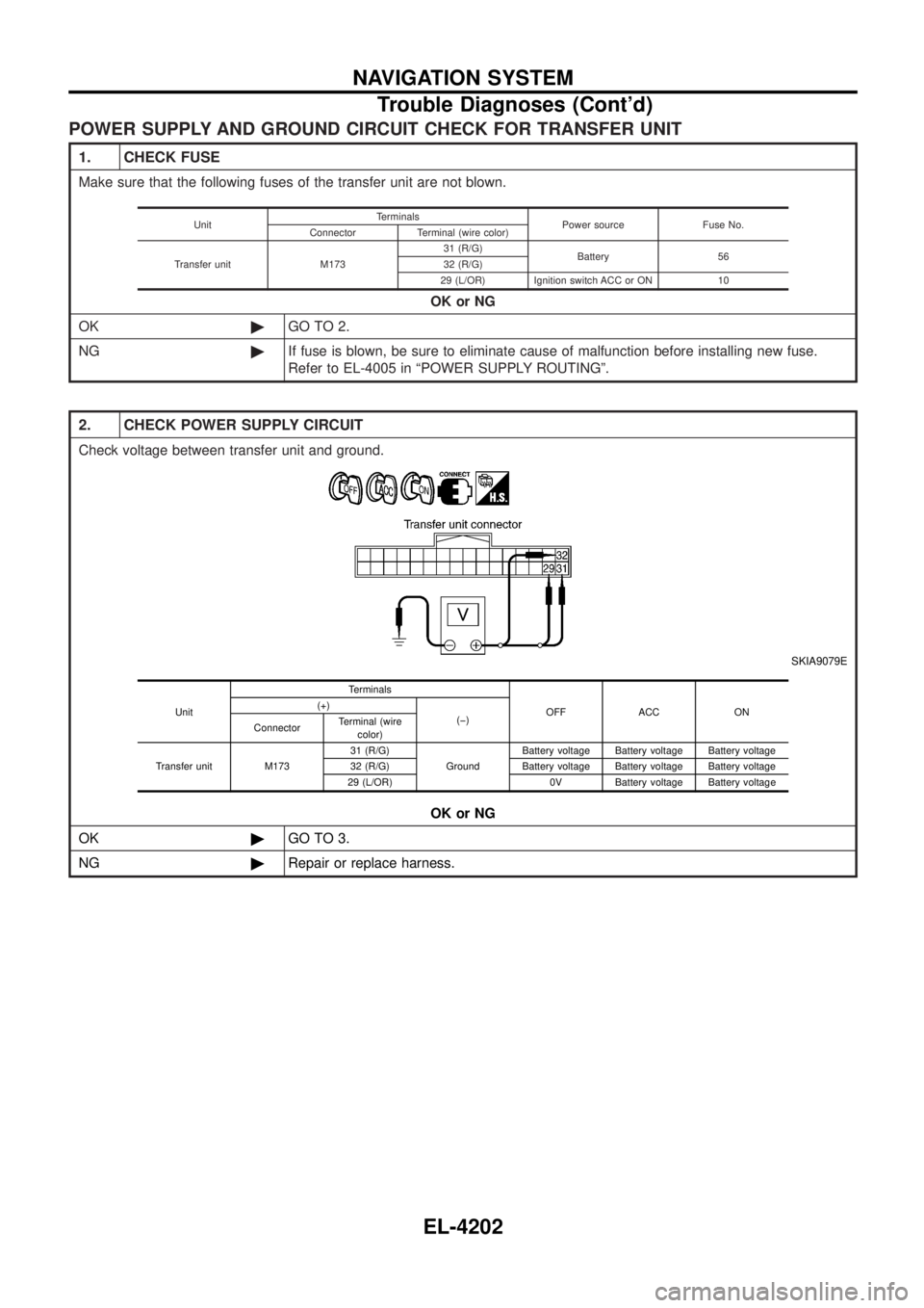
POWER SUPPLY AND GROUND CIRCUIT CHECK FOR TRANSFER UNIT
1. CHECK FUSE
Make sure that the following fuses of the transfer unit are not blown.OK or NG
OK ©GO TO 2.
NG ©If fuse is blown, be sure to eliminate cause of malfunction before installing new fuse.
Refer to EL-4005 in ªPOWER SUPPLY ROUTINGº.
Unit Terminals
Power source Fuse No.
Connector Terminal (wire color)
Transfer unit M173 31 (R/G)
Battery 56
32 (R/G)
29 (L/OR) Ignition switch ACC or ON 10
2. CHECK POWER SUPPLY CIRCUIT
Check voltage between transfer unit and ground.
SKIA9079E
OK or NG
OK ©GO TO 3.
NG ©Repair or replace harness.
Unit Terminals
OFF ACC ON
(+)
(þ)
Connector Terminal (wire
color)
Transfer unit M173 31 (R/G)
GroundBattery voltage Battery voltage Battery voltage
32 (R/G) Battery voltage Battery voltage Battery voltage
29 (L/OR) 0V Battery voltage Battery voltage
NAVIGATION SYSTEM
Trouble Diagnoses (Cont'd)
EL-4202
Page 298 of 579
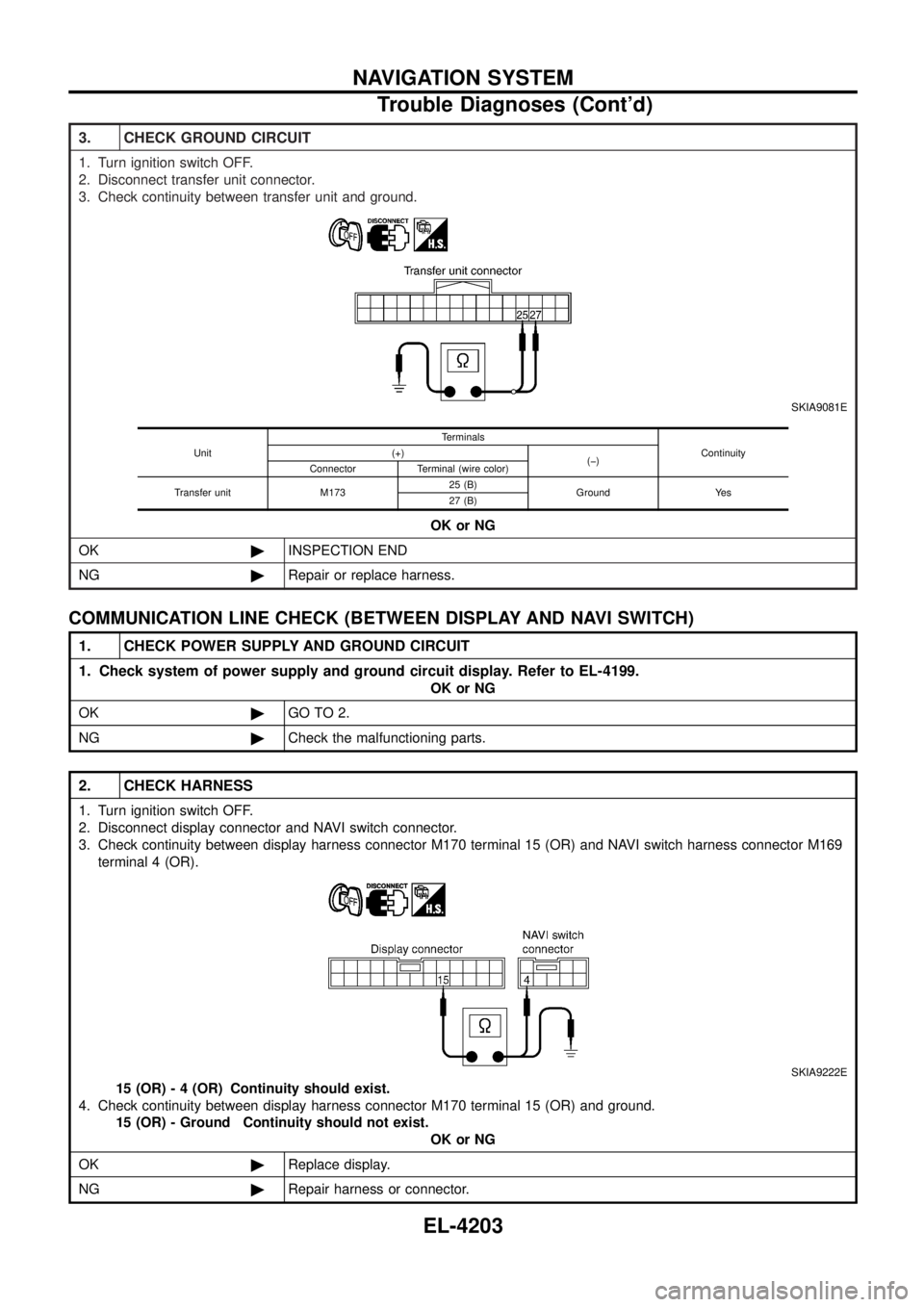
3. CHECK GROUND CIRCUIT
1. Turn ignition switch OFF.
2. Disconnect transfer unit connector.
3. Check continuity between transfer unit and ground.
SKIA9081E
OK or NG
OK ©INSPECTION END
NG ©Repair or replace harness.
Unit Terminals
Continuity
(+)
(þ)
Connector Terminal (wire color)
Transfer unit M173 25 (B)
Ground Yes
27 (B)
COMMUNICATION LINE CHECK (BETWEEN DISPLAY AND NAVI SWITCH)
1. CHECK POWER SUPPLY AND GROUND CIRCUIT
1. Check system of power supply and ground circuit display. Refer to EL-4199.
OK or NG
OK ©GO TO 2.
NG ©Check the malfunctioning parts.
2. CHECK HARNESS
1. Turn ignition switch OFF.
2. Disconnect display connector and NAVI switch connector.
3. Check continuity between display harness connector M170 terminal 15 (OR) and NAVI switch harness connector M169
terminal 4 (OR).
SKIA9222E
15 (OR) - 4 (OR) Continuity should exist.
4. Check continuity between display harness connector M170 terminal 15 (OR) and ground. 15 (OR) - Ground Continuity should not exist. OK or NG
OK ©Replace display.
NG ©Repair harness or connector.
NAVIGATION SYSTEM
Trouble Diagnoses (Cont'd)
EL-4203
Page 299 of 579
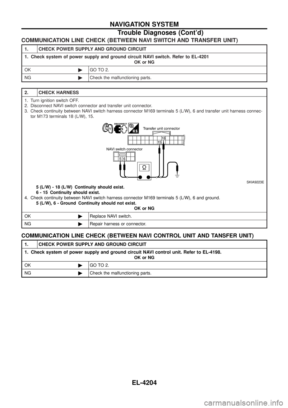
COMMUNICATION LINE CHECK (BETWEEN NAVI SWITCH AND TRANSFER UNIT)
1. CHECK POWER SUPPLY AND GROUND CIRCUIT
1. Check system of power supply and ground circuit NAVI switch. Refer to EL-4201
OK or NG
OK ©GO TO 2.
NG ©Check the malfunctioning parts.
2. CHECK HARNESS
1. Turn ignition switch OFF.
2. Disconnect NAVI switch connector and transfer unit connector.
3. Check continuity between NAVI switch harness connector M169 terminals 5 (L/W), 6 and transfer unit harness connec-
tor M173 terminals 18 (L/W), 15.
SKIA9223E
5 (L/W) - 18 (L/W) Continuity should exist.
6 - 15 Continuity should exist.
4. Check continuity between NAVI switch harness connector M169 terminals 5 (L/W), 6 and ground. 5 (L/W) , 6 - Ground Continuity should not exist.
OK or NG
OK ©Replace NAVI switch.
NG ©Repair harness or connector.
COMMUNICATION LINE CHECK (BETWEEN NAVI CONTROL UNIT AND TANSFER UNIT)
1. CHECK POWER SUPPLY AND GROUND CIRCUIT
1. Check system of power supply and ground circuit NAVI control unit. Refer to EL-4198.
OK or NG
OK ©GO TO 2.
NG ©Check the malfunctioning parts.
NAVIGATION SYSTEM
Trouble Diagnoses (Cont'd)
EL-4204
Page 300 of 579
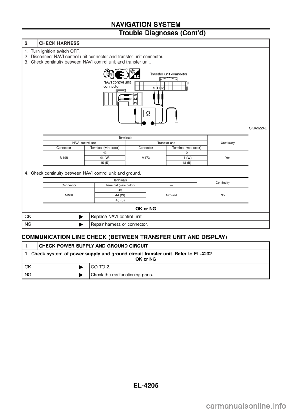
2. CHECK HARNESS
1. Turn ignition switch OFF.
2. Disconnect NAVI control unit connector and transfer unit connector.
3. Check continuity between NAVI control unit and transfer unit.
SKIA9224E
4. Check continuity between NAVI control unit and ground.OK or NG
OK ©Replace NAVI control unit.
NG ©Repair harness or connector.
Terminals
Continuity
NAVI control unit Transfer unit
Connector Terminal (wire color) Connector Terminal (wire color)
M168 43
M173 9
Ye s
44 (W) 11 (W)
45 (B) 13 (B)
Terminals Continuity
Connector Terminal (wire color) Ð
M168 43
Ground No
44 (W)
45 (B)
COMMUNICATION LINE CHECK (BETWEEN TRANSFER UNIT AND DISPLAY)
1. CHECK POWER SUPPLY AND GROUND CIRCUIT
1. Check system of power supply and ground circuit transfer unit. Refer to EL-4202.
OK or NG
OK ©GO TO 2.
NG ©Check the malfunctioning parts.
NAVIGATION SYSTEM
Trouble Diagnoses (Cont'd)
EL-4205