navigation system NISSAN PATROL 2004 Electronic Workshop Manual
[x] Cancel search | Manufacturer: NISSAN, Model Year: 2004, Model line: PATROL, Model: NISSAN PATROL 2004Pages: 579, PDF Size: 26.61 MB
Page 306 of 579

3. CHECK RGB SIGNAL
1. Connect NAVI control unit connector and display connector.
PKIB0553E
2. Turn ignition switch ON.
3. Display ªColor barº by ªCONFIRMATION/ADJUSTMENTº mode.
4. Check the following with CONSULT-ll or oscilloscope.
+When the screen looks bluish.
Voltage signal between NAVI control unit connector M167 terminal 18 (R) and 17.
18 (BR) - 19: Refer to EL-4183.
+ When the screen looks reddish.
Voltage signal between NAVI control unit connector M167 terminal 21 (G) and 17.
21 (W) - 19: Refer to EL-4183.
+ When the screen looks yellowish.
Voltage signal between NAVI control unit connector M167 terminal 15 (B) and 17.
15 (R) - 19: Refer to EL-4183. OK or NG
OK ©Replace display.
NG ©Replace NAVI control unit.
RGB SCREEN IS NOT SHOWN
1. CHECK HARNESS
1. Turn ignition switch OFF.
PKIB0554E
2. Disconnect NAVI control unit connector and display connector.
3. Check continuity between NAVI control unit harness connector M167 terminals 12 (R), 17 and display harness connec-
tor M170 terminals 8 (R), 4.12 (R) - 8 (R) Continuity should exist.
17 - 4 Continuity should exist.
4. Check continuity between NAVI control unit harness connector M167 terminals 12 (R), 17 and ground. 12 (R), 17 - Ground Continuity should not exist. OK or NG
OK ©GO TO 2.
NG ©Repair harness or connector.
NAVIGATION SYSTEM
Trouble Diagnoses (Cont'd)
EL-4211
Page 307 of 579
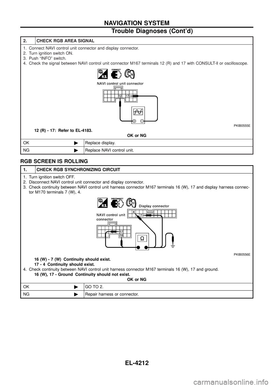
2. CHECK RGB AREA SIGNAL
1. Connect NAVI control unit connector and display connector.
2. Turn ignition switch ON.
3. Push ªINFOº switch.
4. Check the signal between NAVI control unit connector M167 terminals 12 (R) and 17 with CONSULT-ll or oscilloscope.
PKIB0555E
12 (R) - 17: Refer to EL-4183.OK or NG
OK ©Replace display.
NG ©Replace NAVI control unit.
RGB SCREEN IS ROLLING
1. CHECK RGB SYNCHRONIZING CIRCUIT
1. Turn ignition switch OFF.
2. Disconnect NAVI control unit connector and display connector.
3. Check continuity between NAVI control unit harness connector M167 terminals 16 (W), 17 and display harness connec-
tor M170 terminals 7 (W), 4.
PKIB0556E
16 (W) - 7 (W) Continuity should exist.
17 - 4 Continuity should exist.
4. Check continuity between NAVI control unit harness connector M167 terminals 16 (W), 17 and ground. 16 (W), 17 - Ground Continuity should not exist. OK or NG
OK ©GO TO 2.
NG ©Repair harness or connector.
NAVIGATION SYSTEM
Trouble Diagnoses (Cont'd)
EL-4212
Page 308 of 579
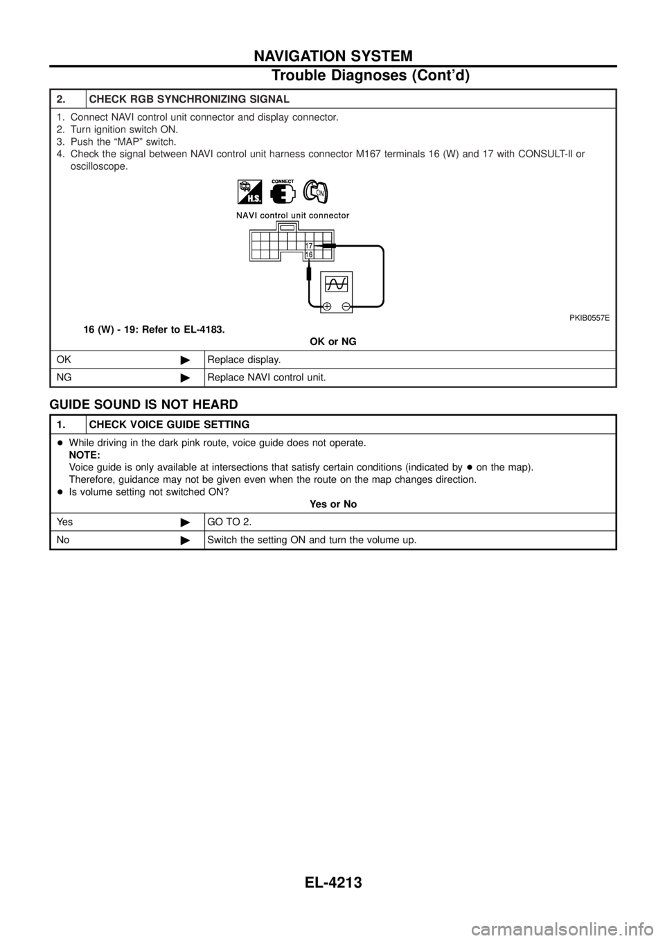
2. CHECK RGB SYNCHRONIZING SIGNAL
1. Connect NAVI control unit connector and display connector.
2. Turn ignition switch ON.
3. Push the ªMAPº switch.
4. Check the signal between NAVI control unit harness connector M167 terminals 16 (W) and 17 with CONSULT-ll oroscilloscope.
PKIB0557E
16 (W) - 19: Refer to EL-4183. OK or NG
OK ©Replace display.
NG ©Replace NAVI control unit.
GUIDE SOUND IS NOT HEARD
1. CHECK VOICE GUIDE SETTING
+While driving in the dark pink route, voice guide does not operate.
NOTE:
Voice guide is only available at intersections that satisfy certain conditions (indicated by +on the map).
Therefore, guidance may not be given even when the route on the map changes direction.
+ Is volume setting not switched ON?
YesorNo
Ye s ©GO TO 2.
No ©Switch the setting ON and turn the volume up.
NAVIGATION SYSTEM
Trouble Diagnoses (Cont'd)
EL-4213
Page 309 of 579
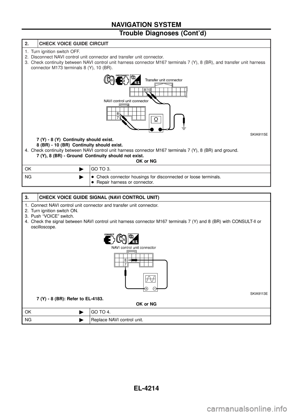
2. CHECK VOICE GUIDE CIRCUIT
1. Turn ignition switch OFF.
2. Disconnect NAVI control unit connector and transfer unit connector.
3. Check continuity between NAVI control unit harness connector M167 terminals 7 (Y), 8 (BR), and transfer unit harnessconnector M173 terminals 8 (Y), 10 (BR).
SKIA9115E
7 (Y) - 8 (Y) Continuity should exist.
8 (BR) - 10 (BR) Continuity should exist.
4. Check continuity between NAVI control unit harness connector M167 terminals 7 (Y), 8 (BR) and ground. 7 (Y), 8 (BR) - Ground Continuity should not exist. OK or NG
OK ©GO TO 3.
NG ©+Check connector housings for disconnected or loose terminals.
+ Repair harness or connector.
3. CHECK VOICE GUIDE SIGNAL (NAVI CONTROL UNIT)
1. Connect NAVI control unit connector and transfer unit connector.
2. Turn ignition switch ON.
3. Push ªVOICEº switch.
4. Check the signal between NAVI control unit harness connector M167 terminals 7 (Y) and 8 (BR) with CONSULT-ll or
oscilloscope.
SKIA9113E
7 (Y) - 8 (BR): Refer to EL-4183. OK or NG
OK ©GO TO 4.
NG ©Replace NAVI control unit.
NAVIGATION SYSTEM
Trouble Diagnoses (Cont'd)
EL-4214
Page 310 of 579
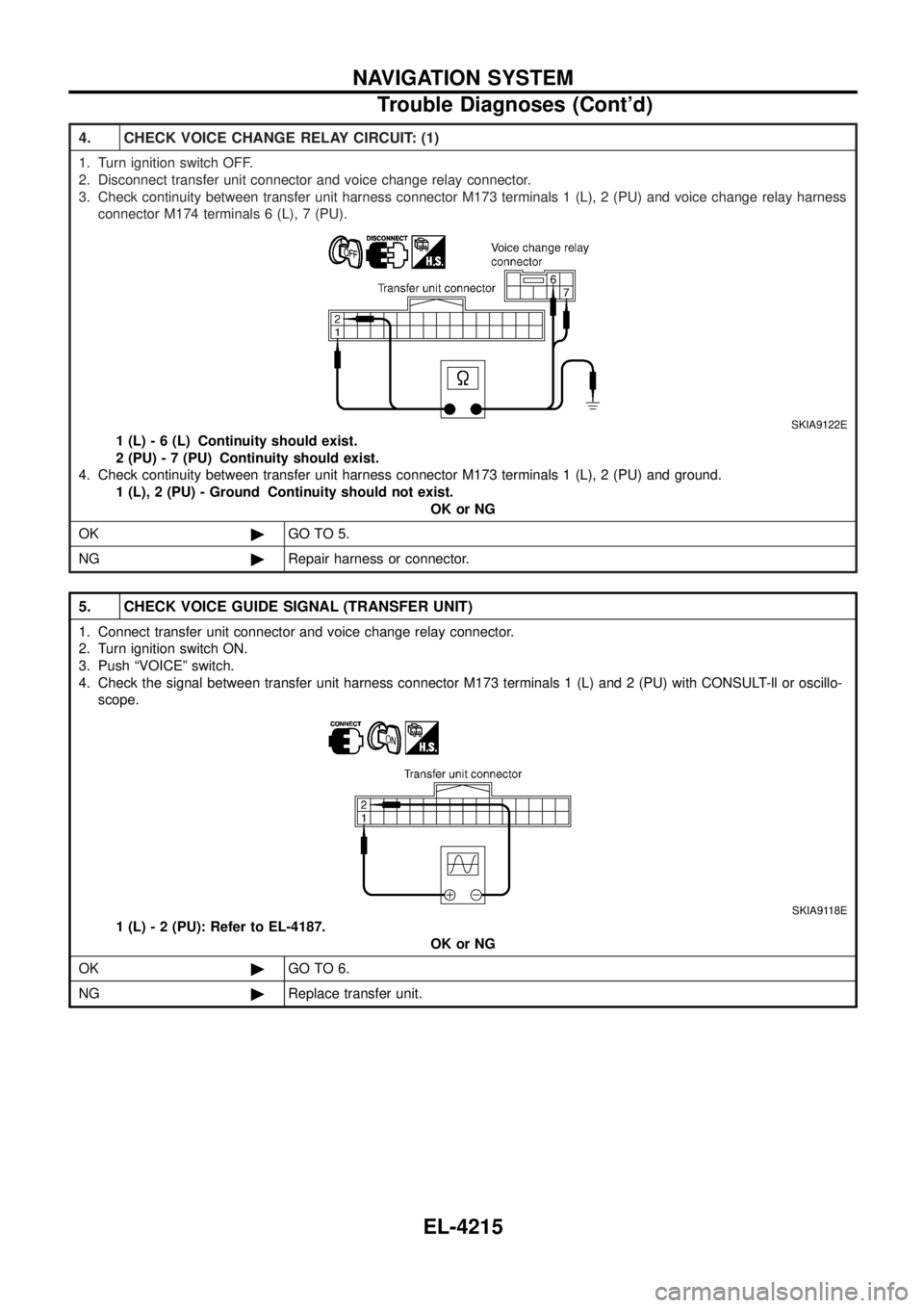
4. CHECK VOICE CHANGE RELAY CIRCUIT: (1)
1. Turn ignition switch OFF.
2. Disconnect transfer unit connector and voice change relay connector.
3. Check continuity between transfer unit harness connector M173 terminals 1 (L), 2 (PU) and voice change relay harnessconnector M174 terminals 6 (L), 7 (PU).
SKIA9122E
1 (L) - 6 (L) Continuity should exist.
2 (PU) - 7 (PU) Continuity should exist.
4. Check continuity between transfer unit harness connector M173 terminals 1 (L), 2 (PU) and ground. 1 (L), 2 (PU) - Ground Continuity should not exist. OK or NG
OK ©GO TO 5.
NG ©Repair harness or connector.
5. CHECK VOICE GUIDE SIGNAL (TRANSFER UNIT)
1. Connect transfer unit connector and voice change relay connector.
2. Turn ignition switch ON.
3. Push ªVOICEº switch.
4. Check the signal between transfer unit harness connector M173 terminals 1 (L) and 2 (PU) with CONSULT-ll or oscillo-
scope.
SKIA9118E
1 (L) - 2 (PU): Refer to EL-4187. OK or NG
OK ©GO TO 6.
NG ©Replace transfer unit.
NAVIGATION SYSTEM
Trouble Diagnoses (Cont'd)
EL-4215
Page 311 of 579
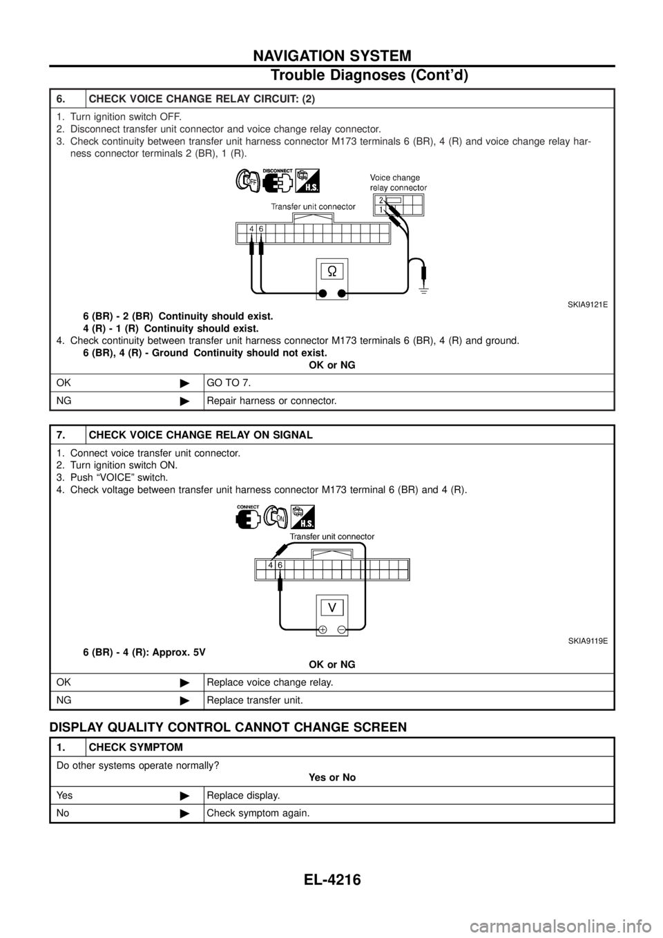
6. CHECK VOICE CHANGE RELAY CIRCUIT: (2)
1. Turn ignition switch OFF.
2. Disconnect transfer unit connector and voice change relay connector.
3. Check continuity between transfer unit harness connector M173 terminals 6 (BR), 4 (R) and voice change relay har-ness connector terminals 2 (BR), 1 (R).
SKIA9121E
6 (BR) - 2 (BR) Continuity should exist.
4 (R) - 1 (R) Continuity should exist.
4. Check continuity between transfer unit harness connector M173 terminals 6 (BR), 4 (R) and ground. 6 (BR), 4 (R) - Ground Continuity should not exist. OK or NG
OK ©GO TO 7.
NG ©Repair harness or connector.
7. CHECK VOICE CHANGE RELAY ON SIGNAL
1. Connect voice transfer unit connector.
2. Turn ignition switch ON.
3. Push ªVOICEº switch.
4. Check voltage between transfer unit harness connector M173 terminal 6 (BR) and 4 (R).
SKIA9119E
6 (BR) - 4 (R): Approx. 5V
OK or NG
OK ©Replace voice change relay.
NG ©Replace transfer unit.
DISPLAY QUALITY CONTROL CANNOT CHANGE SCREEN
1. CHECK SYMPTOM
Do other systems operate normally?
YesorNo
Ye s ©Replace display.
No ©Check symptom again.
NAVIGATION SYSTEM
Trouble Diagnoses (Cont'd)
EL-4216
Page 312 of 579
DRIVING TEST
1. DRIVING TEST 1
1. Scroll the map screen to display the area to make correction. Push ªENTERº and select ªCURRENT LOCATION COR-RECTIONº.
2. Correct direction of the vehicle mark.
3. Perform the distance correction of the ªCONFIRMATION/ADJUSTMENTº mode. NOTE:
Normally, adjustment is not necessary because this system has automatic distance correction function. However, when
a tire chain is ®tted, adjustment in accordance with the tire diameter ratio must be made.
4. Are symptoms applicable to the Example of Symptoms Judged Not Malfunction (EL-4218) present after driving the vehicle? YesorNo
Ye s ©Limit of the location detection capacity of the navigation system.
No ©GO TO 2.
2. DRIVING TEST 2
+Did any malfunction occur when the proper test in the following test patterns is performed?
+ Test pattern
Driving test ®nds the difference between the symptoms monitored with and without each sensor.
Ð Test pattern 1: Test method with no GPS location correction Disconnect the GPS antenna connector connected to the NAVI control unit. Accurately adjust the current location and
the direction, then drive the vehicle.
Ð Test pattern 2: Test method with no map-matching Accurately adjust the current location and the direction. Eject the map DVD-ROM from the NAVI control unit with the
ignition switch turned to OFF, then drive the vehicle. After driving, insert the map DVD-ROM back in the unit, display
the track of the vehicle on the map screen and compare it with the actual road con®guration.
+ Sample tests
Ð
Perform test pattern 1.
Ð
Compare the track of the vehicle on the map screen and the actual road con®guration. For fairly accurate tracking,
plotting shall be made every several hundred meters.
Ð
Drive on a road of which distance is accurately known (by utilizing distance posts on a highway). Calculate the rate of
change (increased/decreased) of the distance by comparing with the actual distance.
Correctio n=1ÐA/B
A: Distance shown on the screen
B: Actual distance YesorNo
Ye s ©+If adjustment is insufficient, perform adjustment again.
+ If any error is found in the map, please let us know.
+ Replace NAVI control unit.
No ©Limit of the location detection capacity of the navigation system.
NAVIGATION SYSTEM
Trouble Diagnoses (Cont'd)
EL-4217
Page 313 of 579
Example of Symptoms Judged Not Malfunction
BASIC OPERATION
Symptom Cause Remedy
No image is shown. Display brightness adjustment is set fully to
DARK side. Adjust the display brightness.
No guide sound is heard. Audio
guide volume is too low or too high. Volume control is set to OFF, MIN or MAX. Adjust the audio guide volume.
Audio guidance is not available while the
vehicle is driving on a dark pink route.
System is not malfunction.
Screen is too dark. Motion of the
image is too slow. Temperature inside the vehicle is low. Wait until the temperature inside the vehicle
reaches the proper temperature.
Small black or bright spots appear
on the screen. Symptom peculiar to a liquid crystal display. System is not malfunction.
VEHICLE MARK
Symptom Cause Remedy
Map screen and BIRDVIEW TName
of the place vary with the screen. Some thinning of the character data is done
to prevent the display becoming to complex.
In some cases and in some locations, the
display contents may differ. The same place
name, street name, etc. may not be dis-
played every time on account of the data pro-
cessing.
System is not malfunction.
Vehicle mark is not positioned cor-
rectly. Vehicle is transferred by ferry or by towing
after its ignition switch is turned to OFF. Drive the vehicle for a while in the GPS sat-
ellite signal receiving condition.
Screen will not switch to nighttime
mode after the lighting switch is
turned ON. The daytime screen is selected by the
ªSWITCH SCREENSº when the last time the
screen dimming setting is done.
Switching between daytime/nighttime screen
may be inhibited by the automatic illumination
adjustment function.
Perform screen dimming and select the night-
time screen by ªSWITCH SCREENSº.
Map screen will not scroll in accor-
dance with the vehicle travel. Current location is not displayed. Push ªMAPº switch to display the current
location.
Vehicle mark will not be shown. Current location is not displayed. Push ªMAPº switch to display the current
location.
Accuracy indicator (GPS satellite
mark) on the map screen stays gray. GPS satellite signal is intercepted because
the vehicle is in or behind a building.
Move the vehicle out to an open space.
GPS satellite signal cannot be received
because an obstacle is placed on top of the
display. Do not place anything in the center on top of
the display.
GPS satellites are located badly. Wait until the location becomes better.
Vehicle location accuracy is low. Accuracy indicator (GPS satellite mark) on
the map screen stays gray.
Current location is not determined.
Vehicle speed setting by the vehicle speed
pulse has been deviated (advanced or
retarded) from the actual vehicle speed
because tire chain is ®tted or the system has
been used on another vehicle. Drive the vehicle for a while [for approx. 30
minutes at approx. 30 km/h (19 MPH)] and
the deviation will be automatically adjusted. If
advancement or retard still occur, perform the
distance adjustment by ªCONFIRMATION/
ADJUSTMENTº mode of diagnosis function.
Map data has error or omission. (Vehicle
mark is always deviated to the same posi-
tion.) As a rule, an updated map DVD-ROM will be
released once a year.
NAVIGATION SYSTEM
EL-4218
Page 314 of 579
DESTINATION, PASSING POINTS, AND MENU ITEMS CANNOT BE SELECTED/SET
Symptom Cause Remedy
Passing point is not searched when
re-searching the route. The vehicle has already passed the passing
point, or the system judged so. To include the passing points that have been
passed into the route again, set the route
again.
Route information will not be dis-
played. Route searching has not been done.
Set the destination and perform route search-
ing.
Vehicle mark is not on the recommended
route. Drive on the recommended route.
Route guide is turned OFF. Turn the route guide ON.
Route information is not available on the dark
pink route. System is not malfunction.
After the route searching, no guide
sign will appear as the vehicle goes
near the entrance/exit to the toll
road. Vehicle mark is not on the recommended
route. (On the display, only guide signs
related to the recommended route will be
shown.)
Drive on the recommended route.
Automatic route searching is not
possible. Vehicle is driving on a highway (gray route),
or no recommended route is available. Drive on a road to be searched. Or re-search
the route manually. In this case, however, the
whole route will be searched.
Performed automatic detour search
(or detour search). However, the
result is the same as that of the pre-
vious search. Performed search with every conditions con-
sidered. However, the result is the same as
that of the previous search.
System is not malfunction.
Passing points cannot be set. More than ®ve passing points were set. Passing points can be set up to ®ve. To stop
at more than ®ve points, perform sharing in
several steps.
When setting the route, the starting
point cannot be selected. The current vehicle location is always set as
the starting point of a route.
System is not malfunction.
Some menu items cannot be
selected. The vehicle is being driven. Stop the vehicle at a safe place and then
operate the system.
VOICE GUIDE
Symptom Cause Remedy
Voice guide will not operate. Note: Voice guide is only available at inter-
sections that satisfy certain conditions (indi-
cated by
+on the map). Therefore, guidance
may not be given even when the route on the
map changes direction. System is not malfunction.
The vehicle is not on the recommended
route. Return to the recommended route or
re-search the route.
Voice guide is turned OFF. Turn the voice guide ON.
Route guide is turned OFF. Turn the route guide ON.
Voice guide does not match the
actual road pattern. Voice guide may vary with the direction to
which the vehicle is turn and the connection
of the road to other roads.
Drive in conformity to the actual traffic rules.
NAVIGATION SYSTEM
Example of Symptoms Judged Not Malfunction
(Cont'd)
EL-4219
Page 315 of 579
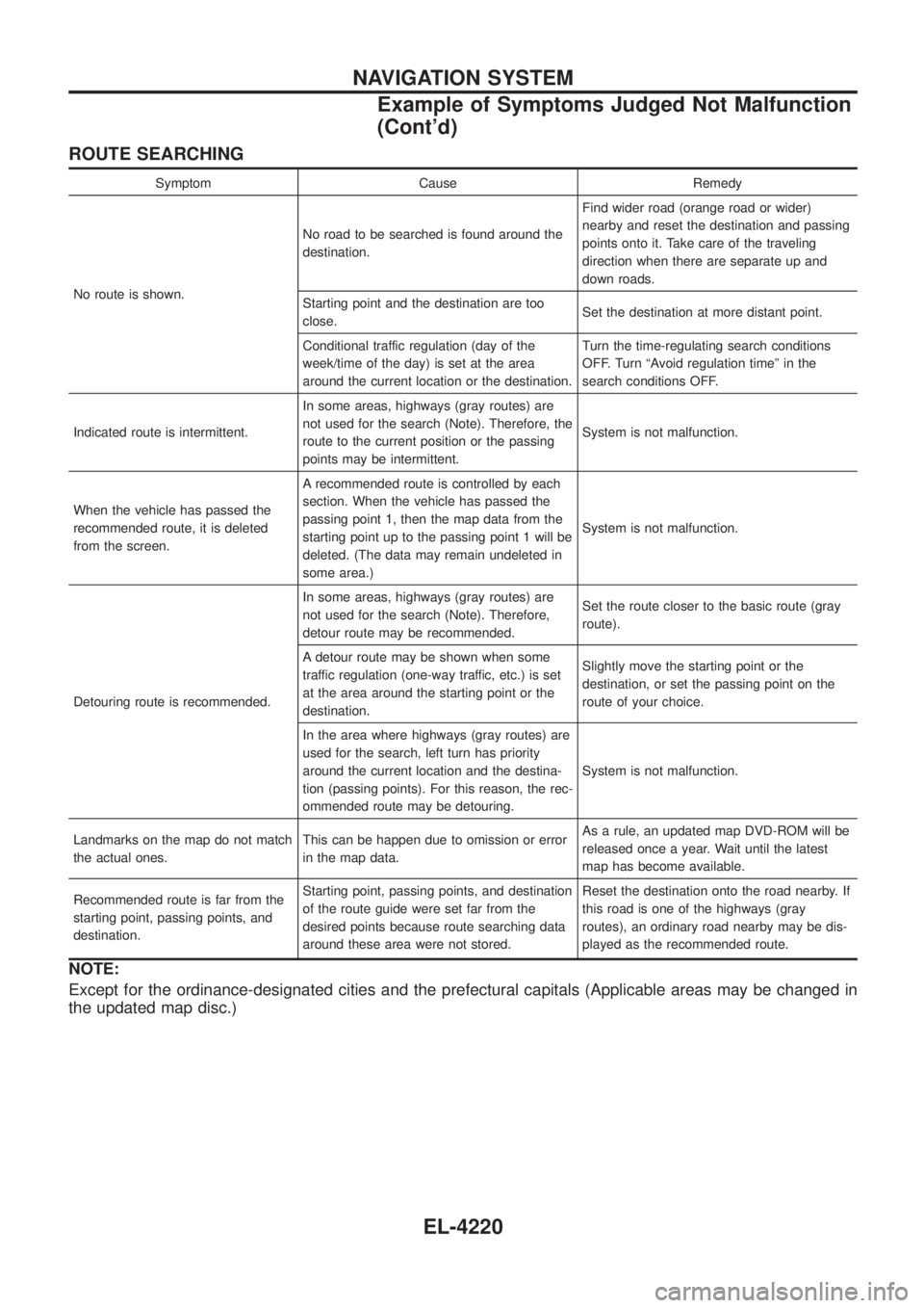
ROUTE SEARCHING
Symptom Cause Remedy
No route is shown. No road to be searched is found around the
destination.
Find wider road (orange road or wider)
nearby and reset the destination and passing
points onto it. Take care of the traveling
direction when there are separate up and
down roads.
Starting point and the destination are too
close. Set the destination at more distant point.
Conditional traffic regulation (day of the
week/time of the day) is set at the area
around the current location or the destination. Turn the time-regulating search conditions
OFF. Turn ªAvoid regulation timeº in the
search conditions OFF.
Indicated route is intermittent. In some areas, highways (gray routes) are
not used for the search (Note). Therefore, the
route to the current position or the passing
points may be intermittent. System is not malfunction.
When the vehicle has passed the
recommended route, it is deleted
from the screen. A recommended route is controlled by each
section. When the vehicle has passed the
passing point 1, then the map data from the
starting point up to the passing point 1 will be
deleted. (The data may remain undeleted in
some area.)
System is not malfunction.
Detouring route is recommended. In some areas, highways (gray routes) are
not used for the search (Note). Therefore,
detour route may be recommended.
Set the route closer to the basic route (gray
route).
A detour route may be shown when some
traffic regulation (one-way traffic, etc.) is set
at the area around the starting point or the
destination. Slightly move the starting point or the
destination, or set the passing point on the
route of your choice.
In the area where highways (gray routes) are
used for the search, left turn has priority
around the current location and the destina-
tion (passing points). For this reason, the rec-
ommended route may be detouring. System is not malfunction.
Landmarks on the map do not match
the actual ones. This can be happen due to omission or error
in the map data. As a rule, an updated map DVD-ROM will be
released once a year. Wait until the latest
map has become available.
Recommended route is far from the
starting point, passing points, and
destination. Starting point, passing points, and destination
of the route guide were set far from the
desired points because route searching data
around these area were not stored. Reset the destination onto the road nearby. If
this road is one of the highways (gray
routes), an ordinary road nearby may be dis-
played as the recommended route.
NOTE:
Except for the ordinance-designated cities and the prefectural capitals (Applicable areas may be changed in
the updated map disc.)
NAVIGATION SYSTEM
Example of Symptoms Judged Not Malfunction
(Cont'd)
EL-4220