wheel NISSAN PATROL 2004 Electronic Repair Manual
[x] Cancel search | Manufacturer: NISSAN, Model Year: 2004, Model line: PATROL, Model: NISSAN PATROL 2004Pages: 579, PDF Size: 26.61 MB
Page 26 of 579
CAUTION:
+Disconnect both battery cables in advance.
+Disconnect air bag system line in advance.
+Never tamper with or force air bag lid open, as this may adversely affect air bag performance.
+Be careful not to scratch pad and other parts.
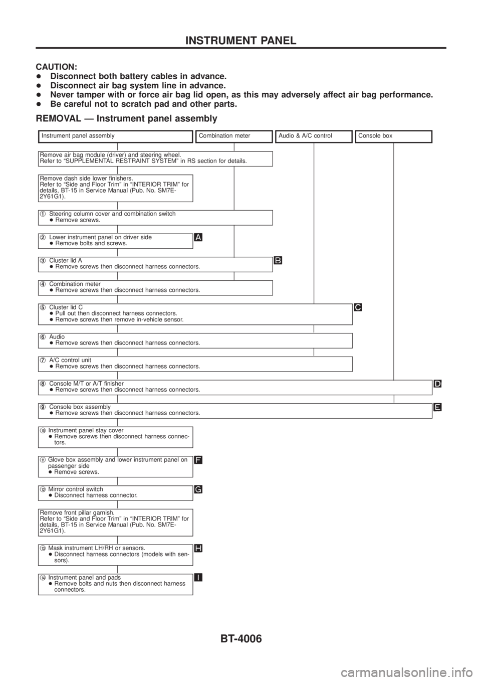
REMOVAL Ð Instrument panel assembly
Instrument panel assemblyCombination meterAudio & A/C controlConsole box
Remove air bag module (driver) and steering wheel.
Refer to ªSUPPLEMENTAL RESTRAINT SYSTEMº in RS section for details.
Remove dash side lower ®nishers.
Refer to ªSide and Floor Trimº in ªINTERIOR TRIMº for
details, BT-15 in Service Manual (Pub. No. SM7E-
2Y61G1).
j1Steering column cover and combination switch
+Remove screws.
j2Lower instrument panel on driver side
+Remove bolts and screws.
j3Cluster lid A
+Remove screws then disconnect harness connectors.
j4Combination meter
+Remove screws then disconnect harness connectors.
j5Cluster lid C
+Pull out then disconnect harness connectors.
+Remove screws then remove in-vehicle sensor.
j6Audio
+Remove screws then disconnect harness connectors.
j7A/C control unit
+Remove screws then disconnect harness connectors.
j8Console M/T or A/T ®nisher
+Remove screws then disconnect harness connectors.
j9Console box assembly
+Remove screws then disconnect harness connectors.
j10Instrument panel stay cover
+Remove screws then disconnect harness connec-
tors.
j11Glove box assembly and lower instrument panel on
passenger side
+Remove screws.
j12Mirror control switch
+Disconnect harness connector.
Remove front pillar garnish.
Refer to ªSide and Floor Trimº in ªINTERIOR TRIMº for
details, BT-15 in Service Manual (Pub. No. SM7E-
2Y61G1).
j13Mask instrument LH/RH or sensors.
+Disconnect harness connectors (models with sen-
sors).
j14Instrument panel and pads
+Remove bolts and nuts then disconnect harness
connectors.
INSTRUMENT PANEL
BT-4006
Page 73 of 579
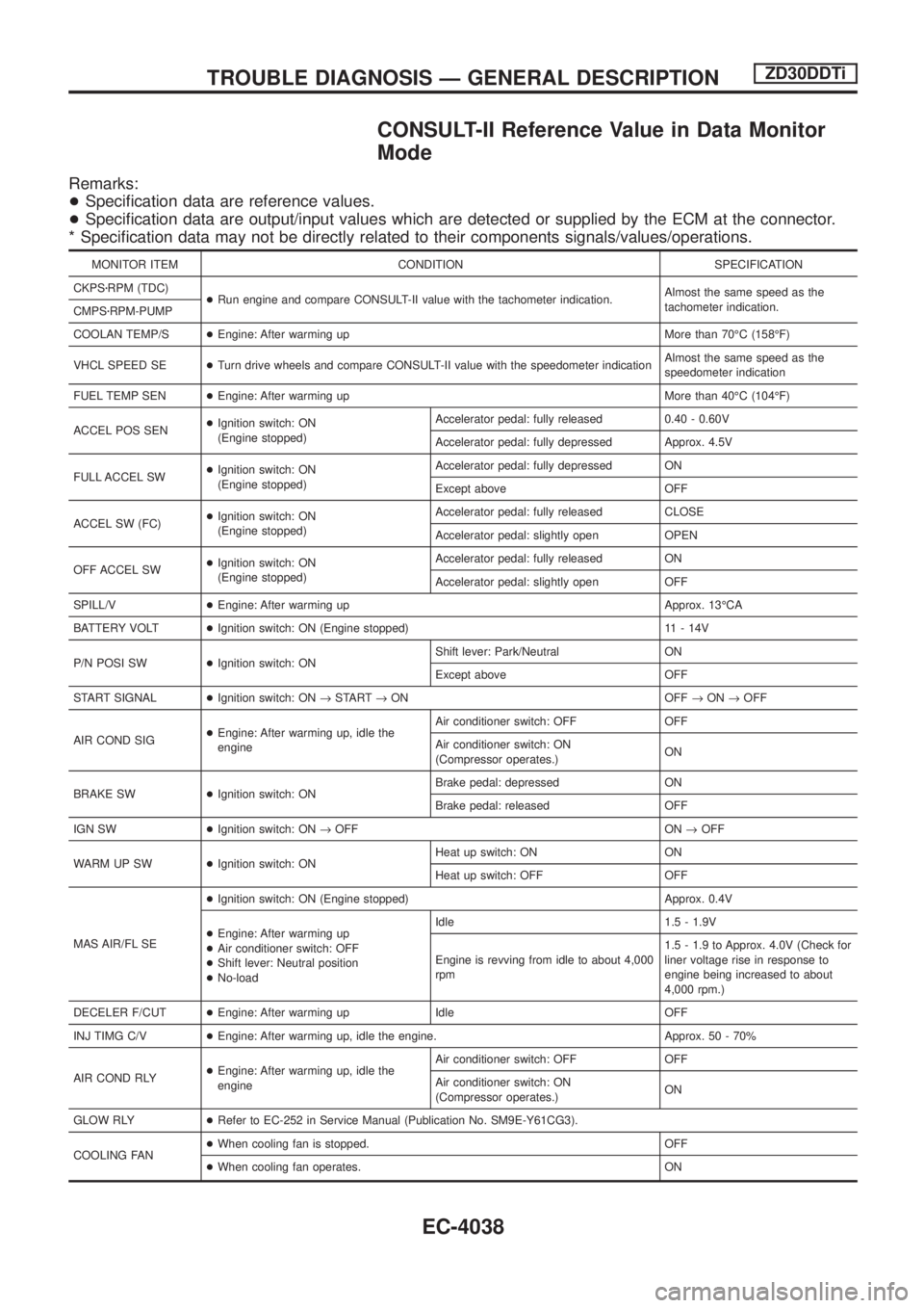
CONSULT-II Reference Value in Data Monitor
Mode
Remarks:
+Speci®cation data are reference values.
+Speci®cation data are output/input values which are detected or supplied by the ECM at the connector.
* Speci®cation data may not be directly related to their components signals/values/operations.
MONITOR ITEM CONDITION SPECIFICATION
CKPSzRPM (TDC)
+Run engine and compare CONSULT-II value with the tachometer indication.Almost the same speed as the
tachometer indication.
CMPSzRPM-PUMP
COOLAN TEMP/S+Engine: After warming up More than 70ÉC (158ÉF)
VHCL SPEED SE+Turn drive wheels and compare CONSULT-II value with the speedometer indicationAlmost the same speed as the
speedometer indication
FUEL TEMP SEN+Engine: After warming up More than 40ÉC (104ÉF)
ACCEL POS SEN+Ignition switch: ON
(Engine stopped)Accelerator pedal: fully released 0.40 - 0.60V
Accelerator pedal: fully depressed Approx. 4.5V
FULL ACCEL SW+Ignition switch: ON
(Engine stopped)Accelerator pedal: fully depressed ON
Except above OFF
ACCEL SW (FC)+Ignition switch: ON
(Engine stopped)Accelerator pedal: fully released CLOSE
Accelerator pedal: slightly open OPEN
OFF ACCEL SW+Ignition switch: ON
(Engine stopped)Accelerator pedal: fully released ON
Accelerator pedal: slightly open OFF
SPILL/V+Engine: After warming up Approx. 13ÉCA
BATTERY VOLT+Ignition switch: ON (Engine stopped) 11 - 14V
P/N POSI SW+Ignition switch: ONShift lever: Park/Neutral ON
Except above OFF
START SIGNAL+Ignition switch: ON®START®ON OFF®ON®OFF
AIR COND SIG+Engine: After warming up, idle the
engineAir conditioner switch: OFF OFF
Air conditioner switch: ON
(Compressor operates.)ON
BRAKE SW+Ignition switch: ONBrake pedal: depressed ON
Brake pedal: released OFF
IGN SW+Ignition switch: ON®OFF ON®OFF
WARM UP SW+Ignition switch: ONHeat up switch: ON ON
Heat up switch: OFF OFF
MAS AIR/FL SE+Ignition switch: ON (Engine stopped) Approx. 0.4V
+Engine: After warming up
+Air conditioner switch: OFF
+Shift lever: Neutral position
+No-loadIdle 1.5 - 1.9V
Engine is revving from idle to about 4,000
rpm1.5 - 1.9 to Approx. 4.0V (Check for
liner voltage rise in response to
engine being increased to about
4,000 rpm.)
DECELER F/CUT+Engine: After warming up Idle OFF
INJ TIMG C/V+Engine: After warming up, idle the engine. Approx. 50 - 70%
AIR COND RLY+Engine: After warming up, idle the
engineAir conditioner switch: OFF OFF
Air conditioner switch: ON
(Compressor operates.)ON
GLOW RLY+Refer to EC-252 in Service Manual (Publication No. SM9E-Y61CG3).
COOLING FAN+When cooling fan is stopped. OFF
+When cooling fan operates. ON
TROUBLE DIAGNOSIS Ð GENERAL DESCRIPTIONZD30DDTi
EC-4038
Page 258 of 579
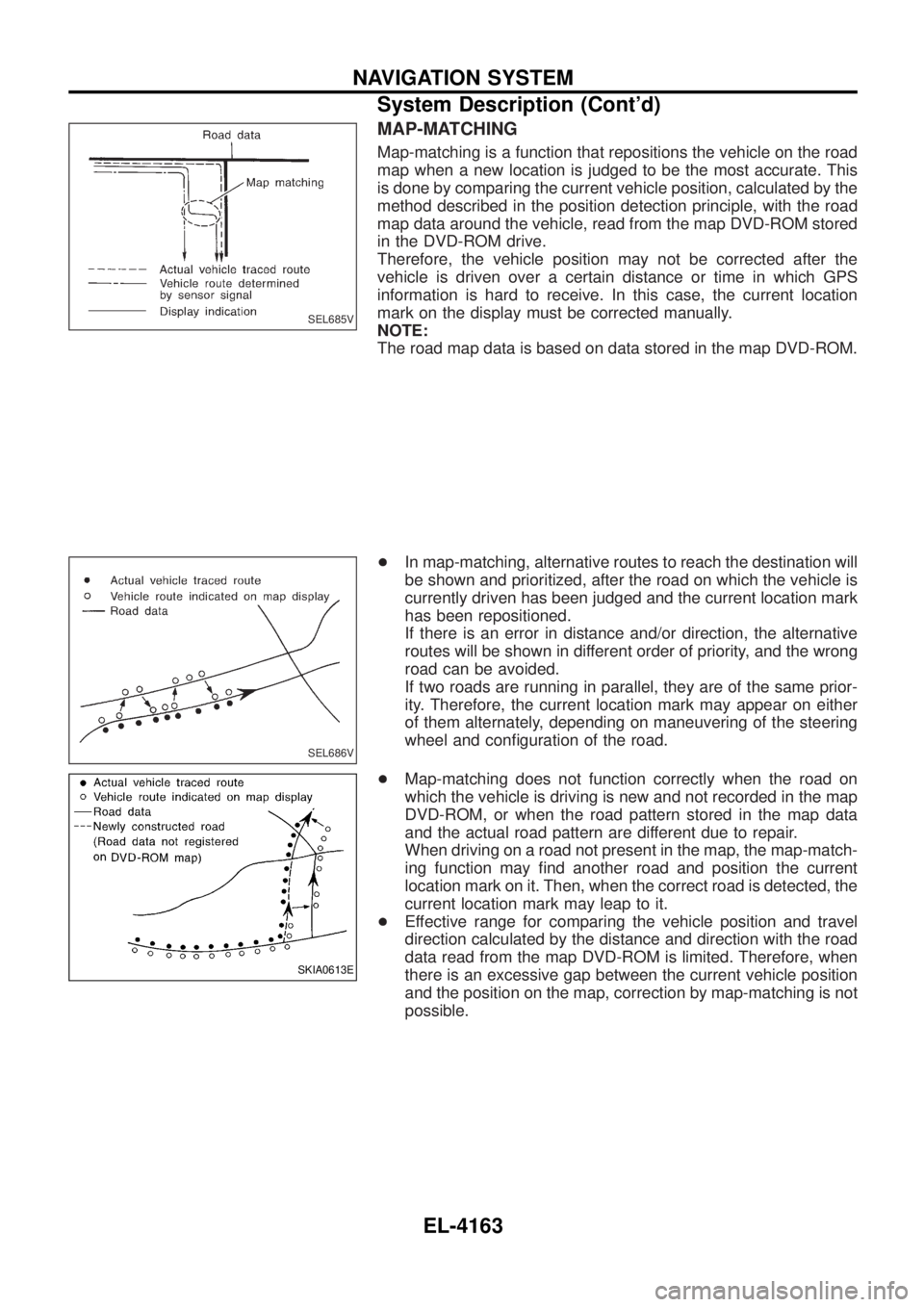
MAP-MATCHING
Map-matching is a function that repositions the vehicle on the road
map when a new location is judged to be the most accurate. This
is done by comparing the current vehicle position, calculated by the
method described in the position detection principle, with the road
map data around the vehicle, read from the map DVD-ROM stored
in the DVD-ROM drive.
Therefore, the vehicle position may not be corrected after the
vehicle is driven over a certain distance or time in which GPS
information is hard to receive. In this case, the current location
mark on the display must be corrected manually.
NOTE:
The road map data is based on data stored in the map DVD-ROM.
+In map-matching, alternative routes to reach the destination will
be shown and prioritized, after the road on which the vehicle is
currently driven has been judged and the current location mark
has been repositioned.
If there is an error in distance and/or direction, the alternative
routes will be shown in different order of priority, and the wrong
road can be avoided.
If two roads are running in parallel, they are of the same prior-
ity. Therefore, the current location mark may appear on either
of them alternately, depending on maneuvering of the steering
wheel and con®guration of the road.
+ Map-matching does not function correctly when the road on
which the vehicle is driving is new and not recorded in the map
DVD-ROM, or when the road pattern stored in the map data
and the actual road pattern are different due to repair.
When driving on a road not present in the map, the map-match-
ing function may ®nd another road and position the current
location mark on it. Then, when the correct road is detected, the
current location mark may leap to it.
+ Effective range for comparing the vehicle position and travel
direction calculated by the distance and direction with the road
data read from the map DVD-ROM is limited. Therefore, when
there is an excessive gap between the current vehicle position
and the position on the map, correction by map-matching is not
possible.
SEL685V
SEL686V
SKIA0613E
NAVIGATION SYSTEM
System Description (Cont'd)
EL-4163
Page 284 of 579
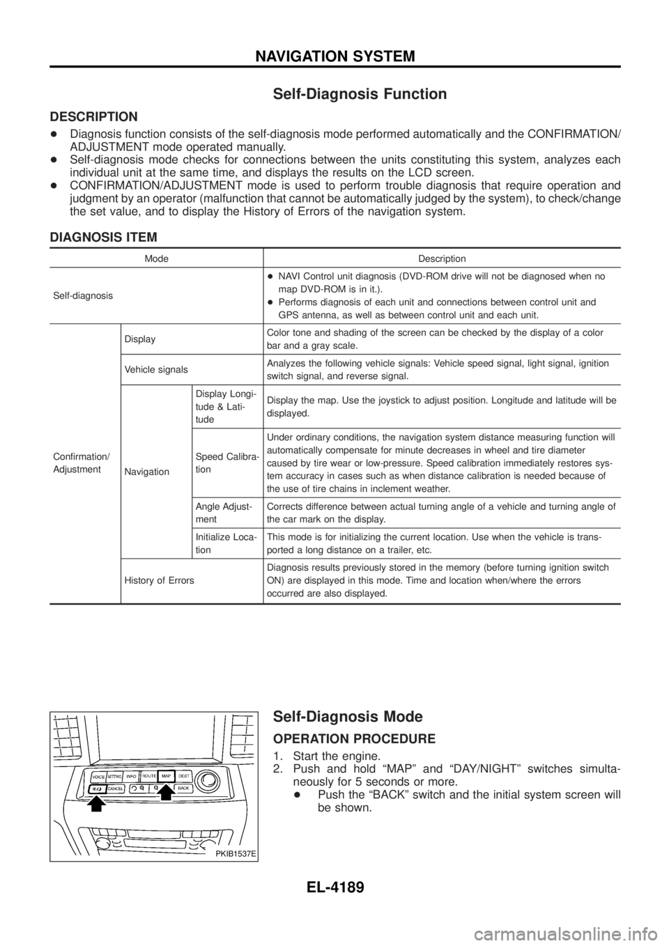
Self-Diagnosis Function
DESCRIPTION
+Diagnosis function consists of the self-diagnosis mode performed automatically and the CONFIRMATION/
ADJUSTMENT mode operated manually.
+ Self-diagnosis mode checks for connections between the units constituting this system, analyzes each
individual unit at the same time, and displays the results on the LCD screen.
+ CONFIRMATION/ADJUSTMENT mode is used to perform trouble diagnosis that require operation and
judgment by an operator (malfunction that cannot be automatically judged by the system), to check/change
the set value, and to display the History of Errors of the navigation system.
DIAGNOSIS ITEM
Mode Description
Self-diagnosis +
NAVI Control unit diagnosis (DVD-ROM drive will not be diagnosed when no
map DVD-ROM is in it.).
+ Performs diagnosis of each unit and connections between control unit and
GPS antenna, as well as between control unit and each unit.
Con®rmation/
Adjustment Display
Color tone and shading of the screen can be checked by the display of a color
bar and a gray scale.
Vehicle signals Analyzes the following vehicle signals: Vehicle speed signal, light signal, ignition
switch signal, and reverse signal.
Navigation Display Longi-
tude & Lati-
tude
Display the map. Use the joystick to adjust position. Longitude and latitude will be
displayed.
Speed Calibra-
tion Under ordinary conditions, the navigation system distance measuring function will
automatically compensate for minute decreases in wheel and tire diameter
caused by tire wear or low-pressure. Speed calibration immediately restores sys-
tem accuracy in cases such as when distance calibration is needed because of
the use of tire chains in inclement weather.
Angle Adjust-
ment Corrects difference between actual turning angle of a vehicle and turning angle of
the car mark on the display.
Initialize Loca-
tion This mode is for initializing the current location. Use when the vehicle is trans-
ported a long distance on a trailer, etc.
History of Errors Diagnosis results previously stored in the memory (before turning ignition switch
ON) are displayed in this mode. Time and location when/where the errors
occurred are also displayed.
Self-Diagnosis Mode
OPERATION PROCEDURE
1. Start the engine.
2. Push and hold ªMAPº and ªDAY/NIGHTº switches simulta-
neously for 5 seconds or more.
+ Push the ªBACKº switch and the initial system screen will
be shown.
PKIB1537E
NAVIGATION SYSTEM
EL-4189
Page 318 of 579
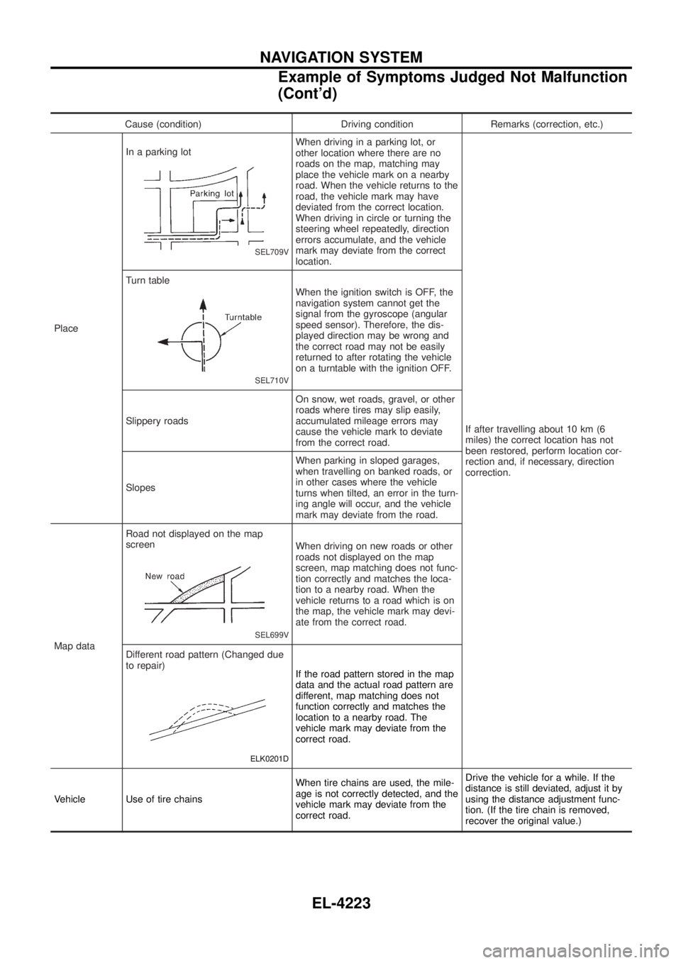
Cause (condition) Driving condition Remarks (correction, etc.)
Place In a parking lot
SEL709V
When driving in a parking lot, or
other location where there are no
roads on the map, matching may
place the vehicle mark on a nearby
road. When the vehicle returns to the
road, the vehicle mark may have
deviated from the correct location.
When driving in circle or turning the
steering wheel repeatedly, direction
errors accumulate, and the vehicle
mark may deviate from the correct
location.
If after travelling about 10 km (6
miles) the correct location has not
been restored, perform location cor-
rection and, if necessary, direction
correction.
Turn table
SEL710V
When the ignition switch is OFF, the
navigation system cannot get the
signal from the gyroscope (angular
speed sensor). Therefore, the dis-
played direction may be wrong and
the correct road may not be easily
returned to after rotating the vehicle
on a turntable with the ignition OFF.
Slippery roads On snow, wet roads, gravel, or other
roads where tires may slip easily,
accumulated mileage errors may
cause the vehicle mark to deviate
from the correct road.
Slopes When parking in sloped garages,
when travelling on banked roads, or
in other cases where the vehicle
turns when tilted, an error in the turn-
ing angle will occur, and the vehicle
mark may deviate from the road.
Map data Road not displayed on the map
screen
SEL699V
When driving on new roads or other
roads not displayed on the map
screen, map matching does not func-
tion correctly and matches the loca-
tion to a nearby road. When the
vehicle returns to a road which is on
the map, the vehicle mark may devi-
ate from the correct road.
Different road pattern (Changed due
to repair)
ELK0201D
If the road pattern stored in the map
data and the actual road pattern are
different, map matching does not
function correctly and matches the
location to a nearby road. The
vehicle mark may deviate from the
correct road.
Vehicle Use of tire chains When tire chains are used, the mile-
age is not correctly detected, and the
vehicle mark may deviate from the
correct road.Drive the vehicle for a while. If the
distance is still deviated, adjust it by
using the distance adjustment func-
tion. (If the tire chain is removed,
recover the original value.)
NAVIGATION SYSTEM
Example of Symptoms Judged Not Malfunction
(Cont'd)
EL-4223
Page 319 of 579
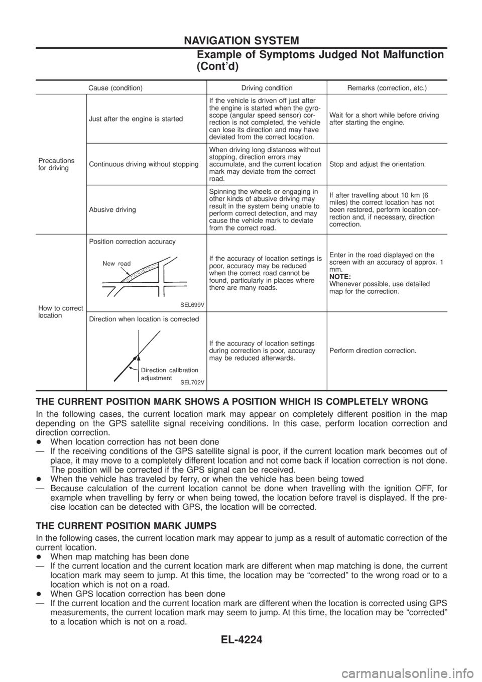
Cause (condition) Driving condition Remarks (correction, etc.)
Precautions
for driving Just after the engine is started
If the vehicle is driven off just after
the engine is started when the gyro-
scope (angular speed sensor) cor-
rection is not completed, the vehicle
can lose its direction and may have
deviated from the correct location.Wait for a short while before driving
after starting the engine.
Continuous driving without stopping When driving long distances without
stopping, direction errors may
accumulate, and the current location
mark may deviate from the correct
road.Stop and adjust the orientation.
Abusive driving Spinning the wheels or engaging in
other kinds of abusive driving may
result in the system being unable to
perform correct detection, and may
cause the vehicle mark to deviate
from the correct road.If after travelling about 10 km (6
miles) the correct location has not
been restored, perform location cor-
rection and, if necessary, direction
correction.
How to correct
location Position correction accuracy
SEL699V
If the accuracy of location settings is
poor, accuracy may be reduced
when the correct road cannot be
found, particularly in places where
there are many roads.
Enter in the road displayed on the
screen with an accuracy of approx. 1
mm.
NOTE:
Whenever possible, use detailed
map for the correction.
Direction when location is corrected
SEL702V
If the accuracy of location settings
during correction is poor, accuracy
may be reduced afterwards. Perform direction correction.
THE CURRENT POSITION MARK SHOWS A POSITION WHICH IS COMPLETELY WRONG
In the following cases, the current location mark may appear on completely different position in the map
depending on the GPS satellite signal receiving conditions. In this case, perform location correction and
direction correction.
+
When location correction has not been done
Ð If the receiving conditions of the GPS satellite signal is poor, if the current location mark becomes out of place, it may move to a completely different location and not come back if location correction is not done.
The position will be corrected if the GPS signal can be received.
+ When the vehicle has traveled by ferry, or when the vehicle has been being towed
Ð Because calculation of the current location cannot be done when travelling with the ignition OFF, for example when travelling by ferry or when being towed, the location before travel is displayed. If the pre-
cise location can be detected with GPS, the location will be corrected.
THE CURRENT POSITION MARK JUMPS
In the following cases, the current location mark may appear to jump as a result of automatic correction of the
current location.
+When map matching has been done
Ð If the current location and the current location mark are different when map matching is done, the current location mark may seem to jump. At this time, the location may be ªcorrectedº to the wrong road or to a
location which is not on a road.
+ When GPS location correction has been done
Ð If the current location and the current location mark are different when the location is corrected using GPS measurements, the current location mark may seem to jump. At this time, the location may be ªcorrectedº
to a location which is not on a road.
NAVIGATION SYSTEM
Example of Symptoms Judged Not Malfunction
(Cont'd)
EL-4224
Page 320 of 579
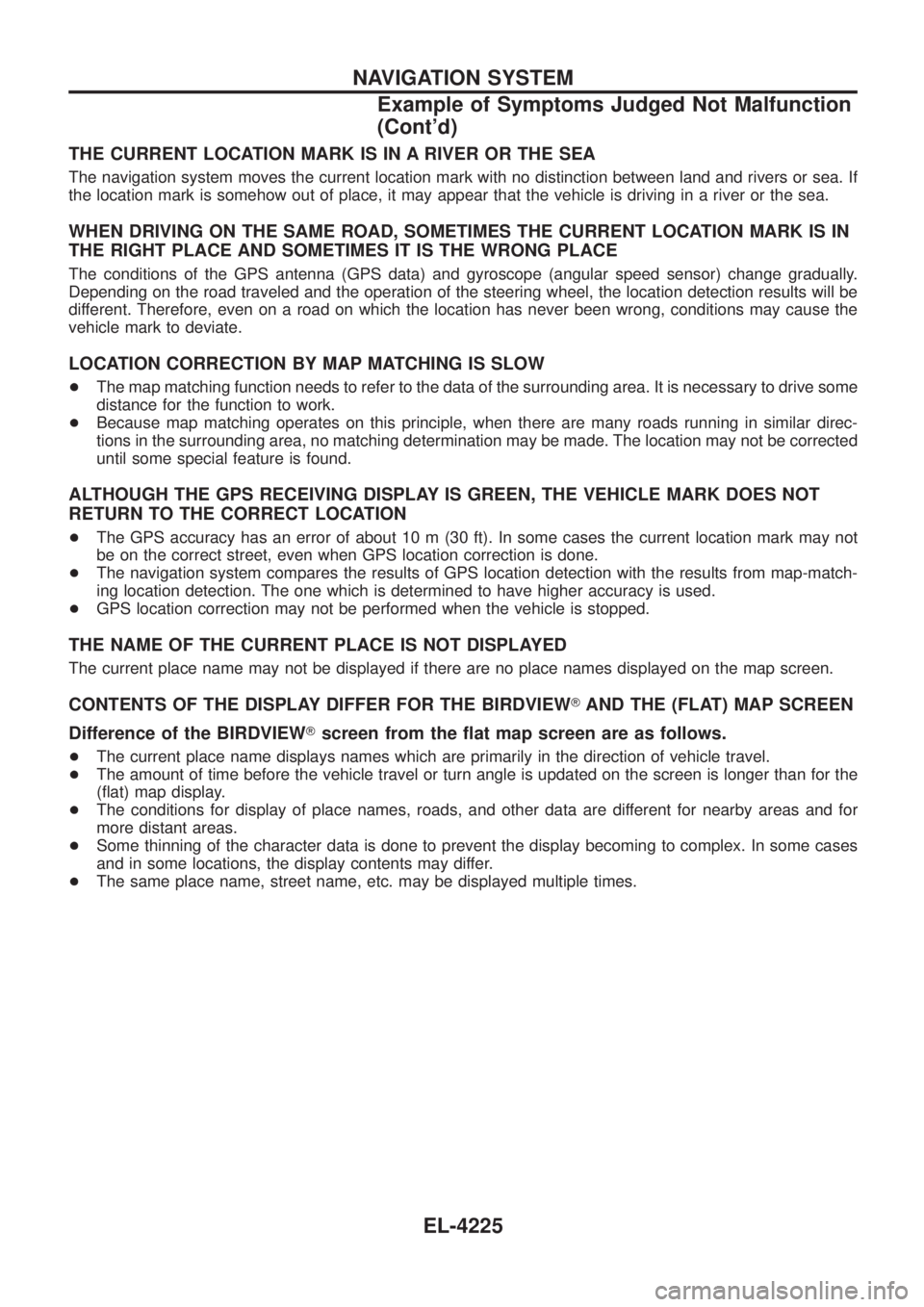
THE CURRENT LOCATION MARK IS IN A RIVER OR THE SEA
The navigation system moves the current location mark with no distinction between land and rivers or sea. If
the location mark is somehow out of place, it may appear that the vehicle is driving in a river or the sea.
WHEN DRIVING ON THE SAME ROAD, SOMETIMES THE CURRENT LOCATION MARK IS IN
THE RIGHT PLACE AND SOMETIMES IT IS THE WRONG PLACE
The conditions of the GPS antenna (GPS data) and gyroscope (angular speed sensor) change gradually.
Depending on the road traveled and the operation of the steering wheel, the location detection results will be
different. Therefore, even on a road on which the location has never been wrong, conditions may cause the
vehicle mark to deviate.
LOCATION CORRECTION BY MAP MATCHING IS SLOW
+The map matching function needs to refer to the data of the surrounding area. It is necessary to drive some
distance for the function to work.
+ Because map matching operates on this principle, when there are many roads running in similar direc-
tions in the surrounding area, no matching determination may be made. The location may not be corrected
until some special feature is found.
ALTHOUGH THE GPS RECEIVING DISPLAY IS GREEN, THE VEHICLE MARK DOES NOT
RETURN TO THE CORRECT LOCATION
+The GPS accuracy has an error of about 10 m (30 ft). In some cases the current location mark may not
be on the correct street, even when GPS location correction is done.
+ The navigation system compares the results of GPS location detection with the results from map-match-
ing location detection. The one which is determined to have higher accuracy is used.
+ GPS location correction may not be performed when the vehicle is stopped.
THE NAME OF THE CURRENT PLACE IS NOT DISPLAYED
The current place name may not be displayed if there are no place names displayed on the map screen.
CONTENTS OF THE DISPLAY DIFFER FOR THE BIRDVIEW TAND THE (FLAT) MAP SCREEN
Difference of the BIRDVIEW Tscreen from the ¯at map screen are as follows.
+ The current place name displays names which are primarily in the direction of vehicle travel.
+ The amount of time before the vehicle travel or turn angle is updated on the screen is longer than for the
(¯at) map display.
+ The conditions for display of place names, roads, and other data are different for nearby areas and for
more distant areas.
+ Some thinning of the character data is done to prevent the display becoming to complex. In some cases
and in some locations, the display contents may differ.
+ The same place name, street name, etc. may be displayed multiple times.
NAVIGATION SYSTEM
Example of Symptoms Judged Not Malfunction
(Cont'd)
EL-4225
Page 471 of 579
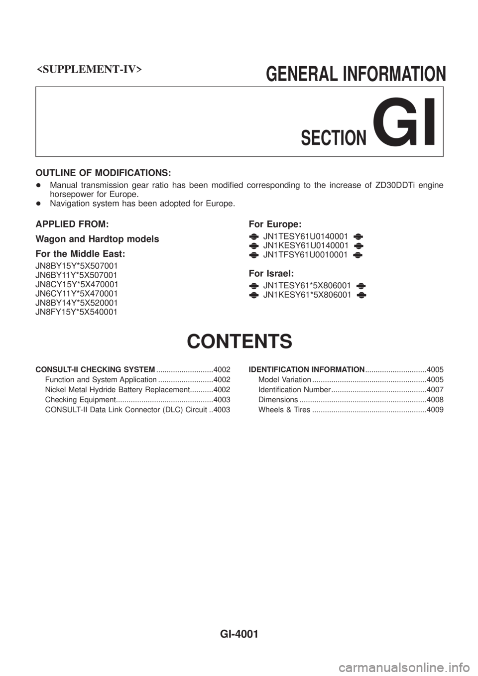
GI
OUTLINE OF MODIFICATIONS:
+Manual transmission gear ratio has been modi®ed corresponding to the increase of ZD30DDTi engine
horsepower for Europe.
+ Navigation system has been adopted for Europe.
APPLIED FROM:
Wagon and Hardtop models
For the Middle East:
JN8BY15Y*5X507001
JN6BY11Y*5X507001
JN8CY15Y*5X470001
JN6CY11Y*5X470001
JN8BY14Y*5X520001
JN8FY15Y*5X540001
For Europe:
JN1TESY61U0140001
JN1KESY61U0140001
JN1TFSY61U0010001
For Israel:
JN1TESY61*5X806001
JN1KESY61*5X806001
CONTENTS
CONSULT-II CHECKING SYSTEM ...........................4002
Function and System Application ..........................4002
Nickel Metal Hydride Battery Replacement...........4002
Checking Equipment..............................................4003
CONSULT-II Data Link Connector (DLC) Circuit ..4003 IDENTIFICATION INFORMATION
.............................4005
Model Variation ......................................................4005
Identi®cation Number .............................................4007
Dimensions ............................................................4008
Wheels & Tires ......................................................4009
GI-4001
Page 476 of 579
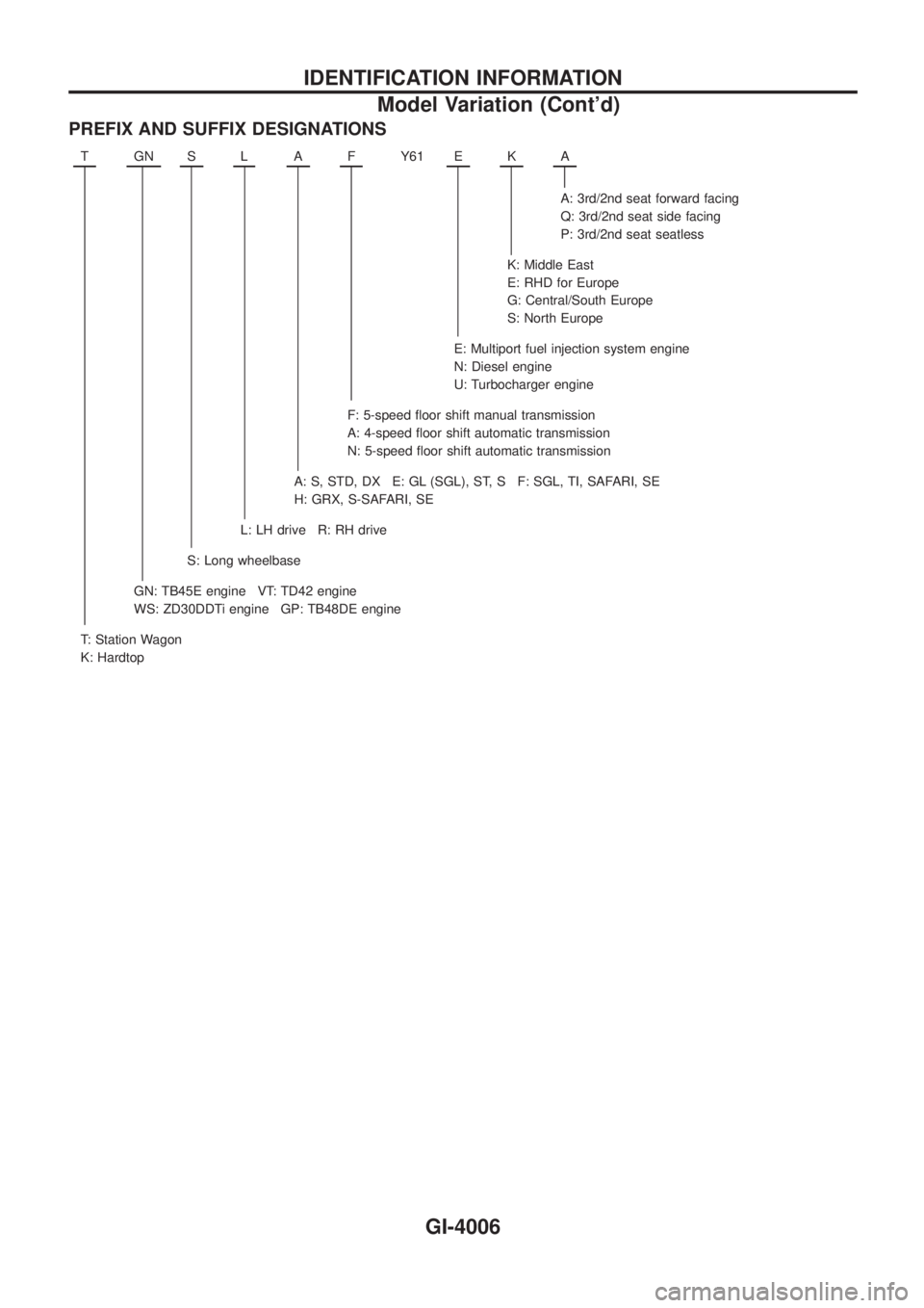
PREFIX AND SUFFIX DESIGNATIONS
TGNSLAFY61 EKA
A: 3rd/2nd seat forward facing
Q: 3rd/2nd seat side facing
P: 3rd/2nd seat seatless
K: Middle East
E: RHD for Europe
G: Central/South Europe
S: North Europe
E: Multiport fuel injection system engine
N: Diesel engine
U: Turbocharger engine
F: 5-speed ¯oor shift manual transmission
A: 4-speed ¯oor shift automatic transmission
N: 5-speed ¯oor shift automatic transmission
A: S, STD, DX E: GL (SGL), ST, S F: SGL, TI, SAFARI, SE
H: GRX, S-SAFARI, SE
L: LH drive R: RH drive
S: Long wheelbase
GN: TB45E engine VT: TD42 engine
WS: ZD30DDTi engine GP: TB48DE engine
T: Station Wagon
K: Hardtop
IDENTIFICATION INFORMATION
Model Variation (Cont'd)
GI-4006
Page 477 of 579
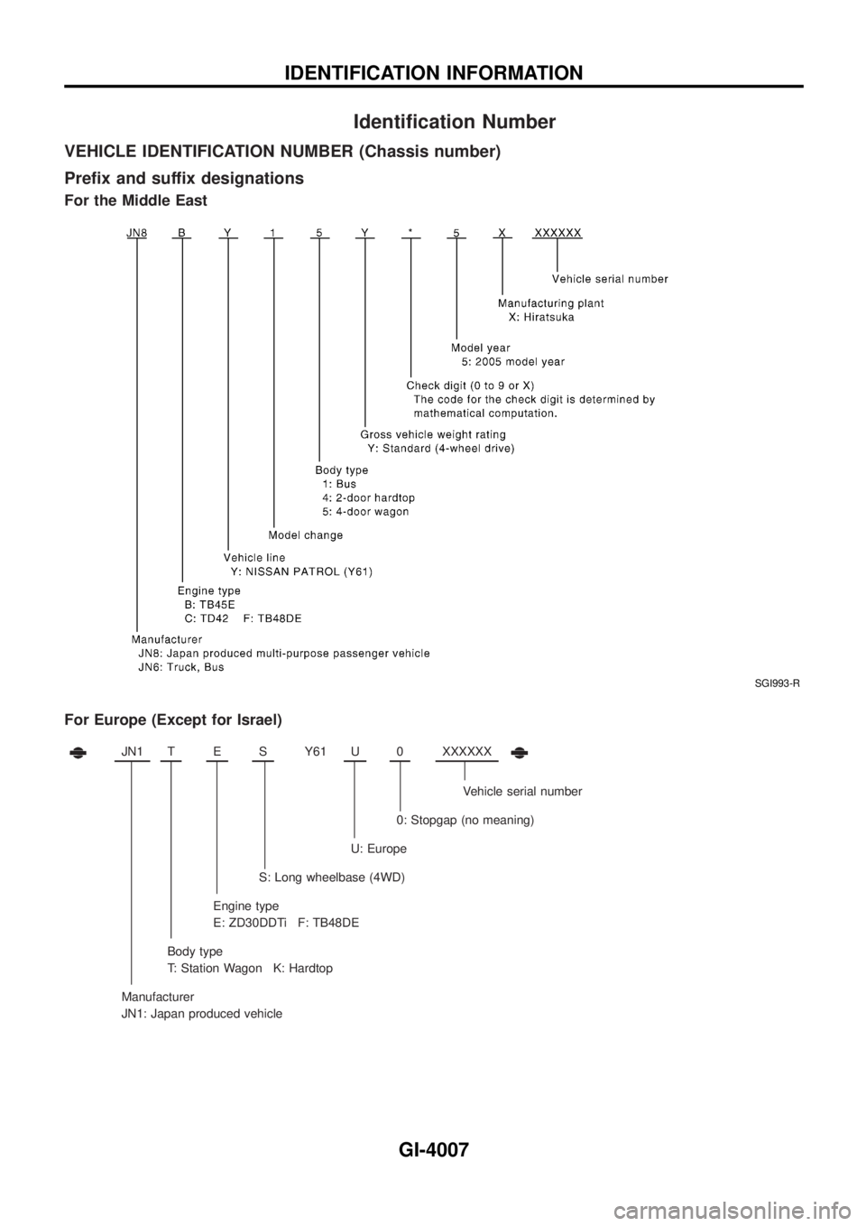
Identi®cation Number
VEHICLE IDENTIFICATION NUMBER (Chassis number)
Pre®x and suffix designations
For the Middle East
For Europe (Except for Israel)
JN1TESY61 U0XXXXXX
Vehicle serial number
0: Stopgap (no meaning)
U: Europe
S: Long wheelbase (4WD)
Engine type
E: ZD30DDTi F: TB48DE
Body type
T: Station Wagon K: Hardtop
Manufacturer
JN1: Japan produced vehicle
SGI993-R
IDENTIFICATION INFORMATION
GI-4007