recommended oil NISSAN PATROL 2006 User Guide
[x] Cancel search | Manufacturer: NISSAN, Model Year: 2006, Model line: PATROL, Model: NISSAN PATROL 2006Pages: 1226, PDF Size: 37.18 MB
Page 990 of 1226
1. Inspect for cracks, fraying, wear or oil adhesion. Replace if
necessary.
The belts should not touch the bottom of the pulley groove.
2. Check drive belt de¯ection by pushing on the belt midway
between pulleys.
Adjust if belt de¯ections exceed the limit.
Unit: mm (in)
Used belt de¯ection
De¯ection of new belt
LimitDe¯ection after
adjustment
Alternator 17 (0.67) 12 - 14 (0.47 - 0.55) 9 - 11 (0.35 - 0.43)
Air conditioner
compressor11 (0.43)7 - 9 (0.28 - 0.35)6 - 8 (0.24 - 0.31)
Power steering oil
pump14 (0.55) 10 - 12 (0.39 - 0.47) 9 - 11 (0.35 - 0.43)
Applied pushing
force98 N (10 kg, 22 lb)
Check drive belt de¯ections when engine is cold.
Changing Engine Oil
WARNING:
+Be careful not to burn yourself, as engine oil is hot.
+Prolonged and repeated contact with used engine oil may
cause skin cancer; try to avoid direct skin contact with
used oil. If skin contact is made, wash thoroughly with
soap or hand cleaner as soon as possible.
1. Warm up engine, and check for oil leakage from engine com-
ponents.
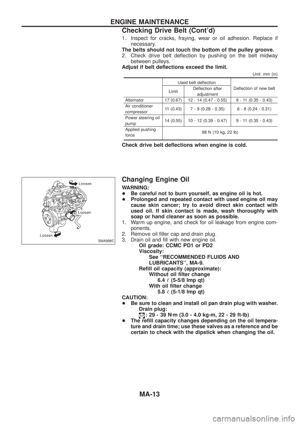
2. Remove oil ®ller cap and drain plug.
3. Drain oil and ®ll with new engine oil.
Oil grade: CCMC PD1 or PD2
Viscosity:
See ``RECOMMENDED FLUIDS AND
LUBRICANTS'', MA-9.
Re®ll oil capacity (approximate):
Without oil ®lter change
6.4!(5-5/8 Imp qt)
With oil ®lter change
5.8!(5-1/8 Imp qt)
CAUTION:
+Be sure to clean and install oil pan drain plug with washer.
Drain plug:
:29-39Nzm (3.0 - 4.0 kg-m, 22 - 29 ft-lb)
+The re®ll capacity changes depending on the oil tempera-
ture and drain time; use these valves as a reference and be
certain to check with the dipstick when changing the oil.
SMA998C
ENGINE MAINTENANCE
Checking Drive Belt (Cont'd)
MA-13
Page 997 of 1226
Checking Exhaust System
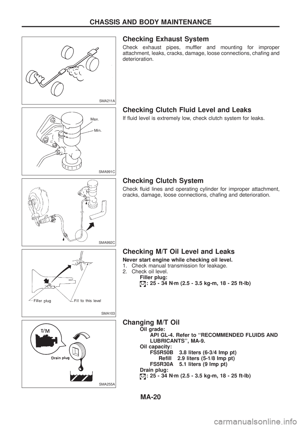
Check exhaust pipes, muffler and mounting for improper
attachment, leaks, cracks, damage, loose connections, cha®ng and
deterioration.
Checking Clutch Fluid Level and Leaks
If ¯uid level is extremely low, check clutch system for leaks.
Checking Clutch System
Check ¯uid lines and operating cylinder for improper attachment,
cracks, damage, loose connections, cha®ng and deterioration.
Checking M/T Oil Level and Leaks
Never start engine while checking oil level.
1. Check manual transmission for leakage.
2. Check oil level.
Filler plug:
:25-34Nzm (2.5 - 3.5 kg-m, 18 - 25 ft-lb)
Changing M/T Oil
Oil grade:
API GL-4. Refer to ``RECOMMENDED FLUIDS AND
LUBRICANTS'', MA-9.
Oil capacity:
FS5R50B 3.8 liters (6-3/4 Imp pt)
Re®ll 2.9 liters (5-1/8 Imp pt)
FS5R30A 5.1 liters (9 Imp pt)
Drain plug:
:25-34Nzm (2.5 - 3.5 kg-m, 18 - 25 ft-lb)
SMA211A
SMA991C
SMA992C
SMA103
SMA255A
CHASSIS AND BODY MAINTENANCE
MA-20
Page 999 of 1226
Checking Differential Gear Oil
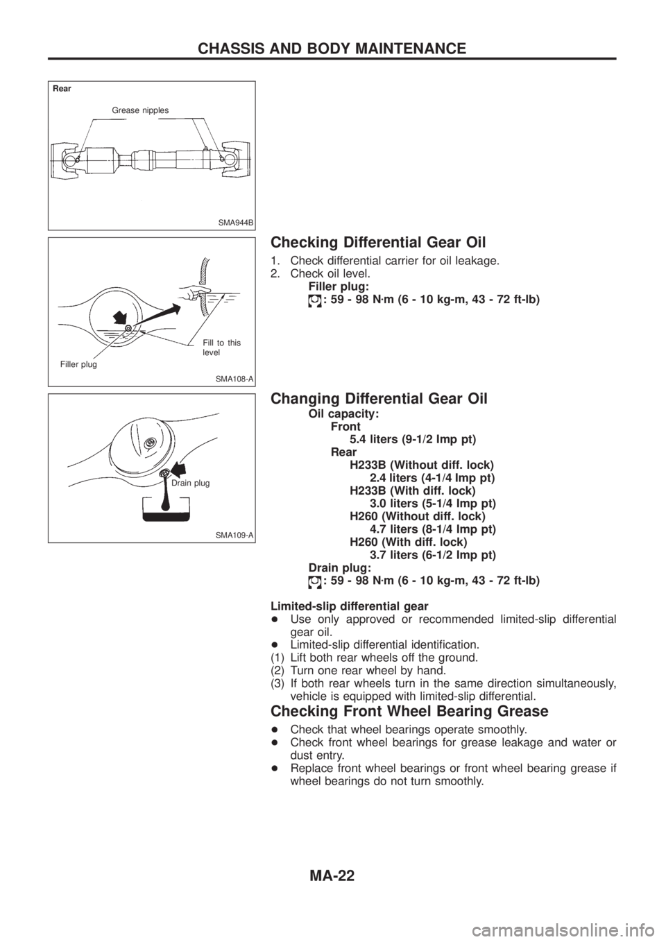
1. Check differential carrier for oil leakage.
2. Check oil level.Filler plug:
:59-98N zm (6 - 10 kg-m, 43 - 72 ft-lb)
Changing Differential Gear Oil
Oil capacity:
Front5.4 liters (9-1/2 Imp pt)
Rear H233B (Without diff. lock) 2.4 liters(4-1/4 Imppt)
H233B (With diff. lock) 3.0 liters (5-1/4 Imp pt)
H260 (Without diff. lock) 4.7 liters (8-1/4 Imp pt)
H260 (With diff. lock) 3.7 liters (6-1/2 Imp pt)
Drain plug:
:59-98N zm (6 - 10 kg-m, 43 - 72 ft-lb)
Limited-slip differential gear
+ Use only approved or recommended limited-slip differential
gear oil.
+ Limited-slip differential identi®cation.
(1) Lift both rear wheels off the ground.
(2) Turn one rear wheel by hand.
(3) If both rear wheels turn in the same direction simultaneously, vehicle is equipped with limited-slip differential.
Checking Front Wheel Bearing Grease
+Check that wheel bearings operate smoothly.
+ Check front wheel bearings for grease leakage and water or
dust entry.
+ Replace front wheel bearings or front wheel bearing grease if
wheel bearings do not turn smoothly.
SMA944B
Grease nipples
Rear
SMA108-A
Filler plug
Fill to this
level
SMA109-A
Drain plug
CHASSIS AND BODY MAINTENANCE
MA-22
Page 1000 of 1226
Repacking Front Wheel Bearing and Axle Joint
Grease
FRONT WHEEL BEARING GREASE
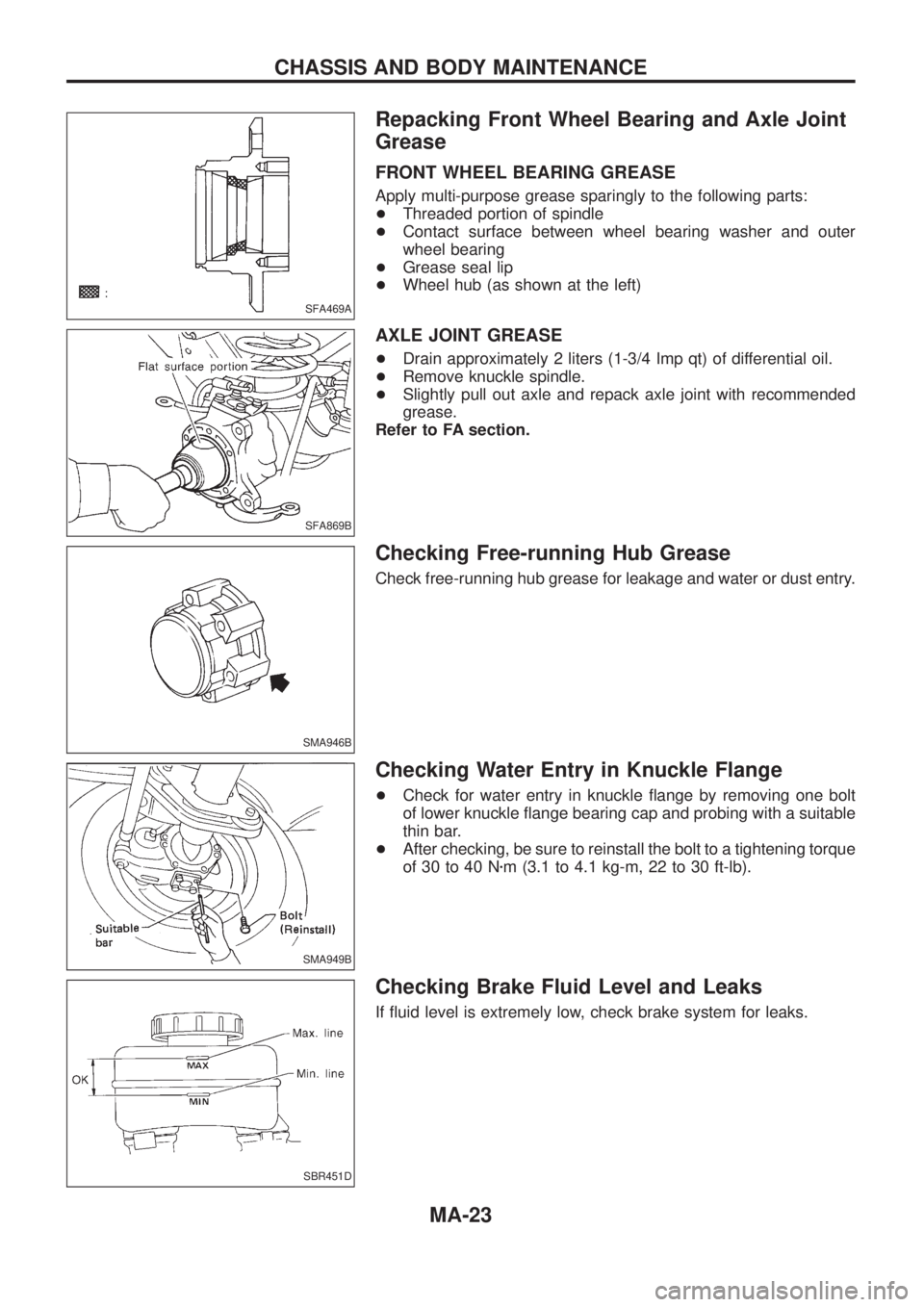
Apply multi-purpose grease sparingly to the following parts:
+Threaded portion of spindle
+Contact surface between wheel bearing washer and outer
wheel bearing
+Grease seal lip
+Wheel hub (as shown at the left)
AXLE JOINT GREASE
+Drain approximately 2 liters (1-3/4 Imp qt) of differential oil.
+Remove knuckle spindle.
+Slightly pull out axle and repack axle joint with recommended
grease.
Refer to FA section.
Checking Free-running Hub Grease
Check free-running hub grease for leakage and water or dust entry.
Checking Water Entry in Knuckle Flange
+Check for water entry in knuckle ¯ange by removing one bolt
of lower knuckle ¯ange bearing cap and probing with a suitable
thin bar.
+After checking, be sure to reinstall the bolt to a tightening torque
of 30 to 40 Nzm (3.1 to 4.1 kg-m, 22 to 30 ft-lb).
Checking Brake Fluid Level and Leaks
If ¯uid level is extremely low, check brake system for leaks.
SFA469A
SFA869B
SMA946B
SMA949B
SBR451D
CHASSIS AND BODY MAINTENANCE
MA-23
Page 1003 of 1226
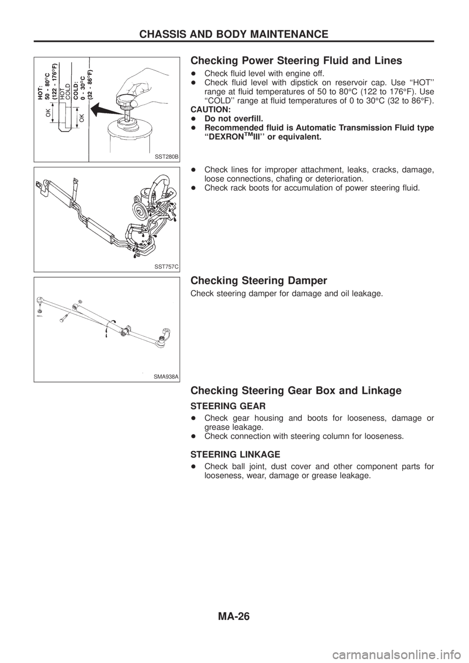
Checking Power Steering Fluid and Lines
+Check ¯uid level with engine off.
+Check ¯uid level with dipstick on reservoir cap. Use ``HOT''
range at ¯uid temperatures of 50 to 80ÉC (122 to 176ÉF). Use
``COLD'' range at ¯uid temperatures of 0 to 30ÉC (32 to 86ÉF).
CAUTION:
+Do not over®ll.
+Recommended ¯uid is Automatic Transmission Fluid type
``DEXRON
TMIII'' or equivalent.
+Check lines for improper attachment, leaks, cracks, damage,
loose connections, cha®ng or deterioration.
+Check rack boots for accumulation of power steering ¯uid.
Checking Steering Damper
Check steering damper for damage and oil leakage.
Checking Steering Gear Box and Linkage
STEERING GEAR
+Check gear housing and boots for looseness, damage or
grease leakage.
+Check connection with steering column for looseness.
STEERING LINKAGE
+Check ball joint, dust cover and other component parts for
looseness, wear, damage or grease leakage.
SST280B
SST757C
SMA938A
CHASSIS AND BODY MAINTENANCE
MA-26
Page 1053 of 1226
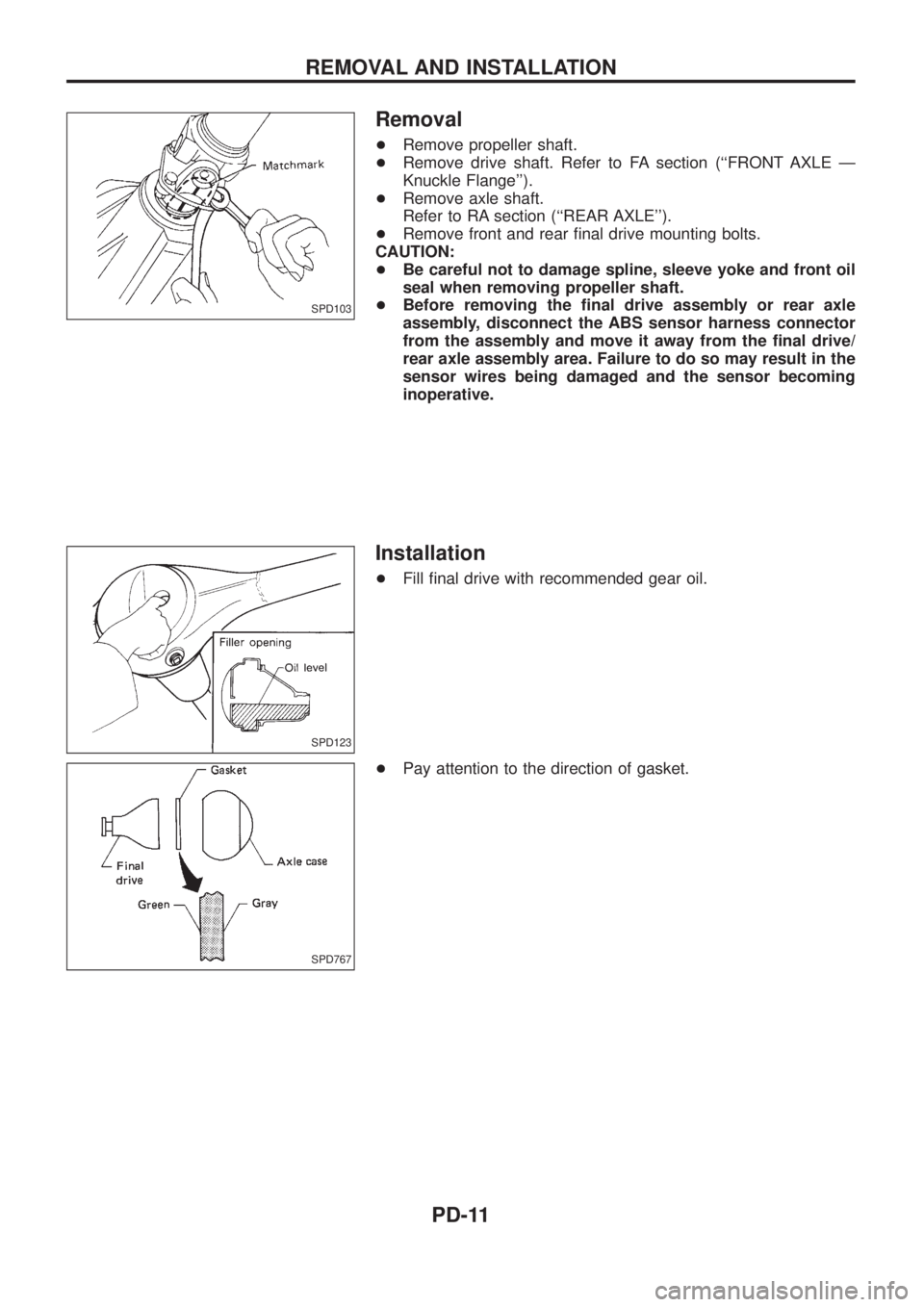
Removal
+Remove propeller shaft.
+Remove drive shaft. Refer to FA section (``FRONT AXLE Ð
Knuckle Flange'').
+Remove axle shaft.
Refer to RA section (``REAR AXLE'').
+Remove front and rear ®nal drive mounting bolts.
CAUTION:
+Be careful not to damage spline, sleeve yoke and front oil
seal when removing propeller shaft.
+Before removing the ®nal drive assembly or rear axle
assembly, disconnect the ABS sensor harness connector
from the assembly and move it away from the ®nal drive/
rear axle assembly area. Failure to do so may result in the
sensor wires being damaged and the sensor becoming
inoperative.
Installation
+Fill ®nal drive with recommended gear oil.
+Pay attention to the direction of gasket.
SPD103
SPD123
SPD767
REMOVAL AND INSTALLATION
PD-11
Page 1174 of 1226
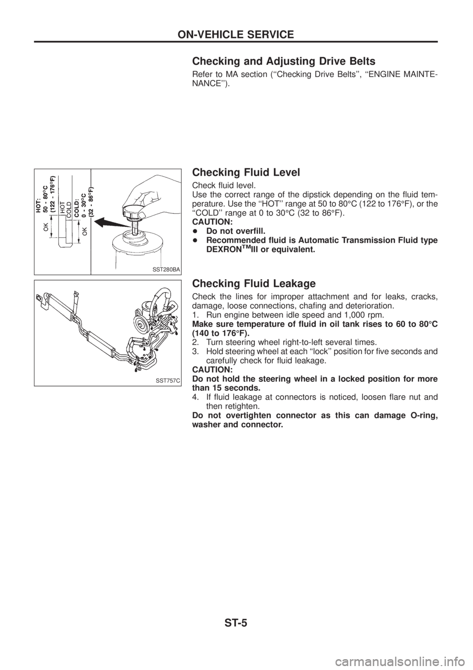
Checking and Adjusting Drive Belts
Refer to MA section (``Checking Drive Belts'', ``ENGINE MAINTE-
NANCE'').
Checking Fluid Level
Check ¯uid level.
Use the correct range of the dipstick depending on the ¯uid tem-
perature. Use the ``HOT'' range at 50 to 80ÉC (122 to 176ÉF), or the
``COLD'' range at 0 to 30ÉC (32 to 86ÉF).
CAUTION:
+Do not over®ll.
+Recommended ¯uid is Automatic Transmission Fluid type
DEXRON
TMIII or equivalent.
Checking Fluid Leakage
Check the lines for improper attachment and for leaks, cracks,
damage, loose connections, cha®ng and deterioration.
1. Run engine between idle speed and 1,000 rpm.
Make sure temperature of ¯uid in oil tank rises to 60 to 80ÉC
(140 to 176ÉF).
2. Turn steering wheel right-to-left several times.
3. Hold steering wheel at each ``lock'' position for ®ve seconds and
carefully check for ¯uid leakage.
CAUTION:
Do not hold the steering wheel in a locked position for more
than 15 seconds.
4. If ¯uid leakage at connectors is noticed, loosen ¯are nut and
then retighten.
Do not overtighten connector as this can damage O-ring,
washer and connector.
SST280BA
SST757C
ON-VEHICLE SERVICE
ST-5
Page 1201 of 1226

Removal
1. Drain ¯uid and oil from transfer and transmission (M/T model
only).
2. Remove exhaust front and rear tubes. Refer to FE section
(``EXHAUST SYSTEM'').
3. Remove front and rear propeller shaft. Refer to PD section
(``Removal and Installation'', ``PROPELLER SHAFT'').
4. Disconnect neutral position switch and 4WD switch harness
connectors.
5. Remove transfer control lever from transfer cross shaft.
6. Remove transfer from transmission.
WARNING:
Support transfer while removing it.
Installation
+Apply recommended sealant to mating surface to transmission.
(M/T models only)
Recommended sealant:
Genuine anaerobic liquid gasket, Three Bond
TB1215, Loctite Part No. 51813 or equivalent
+Tighten transfer bolts.
Transfer ®xing bolts:
:32-42Nzm (3.3 - 4.3 kg-m, 24 - 31 ft-lb)
SMT251D
SMT268D
SMT176BA
REMOVAL AND INSTALLATION
TF-8
Page 1220 of 1226
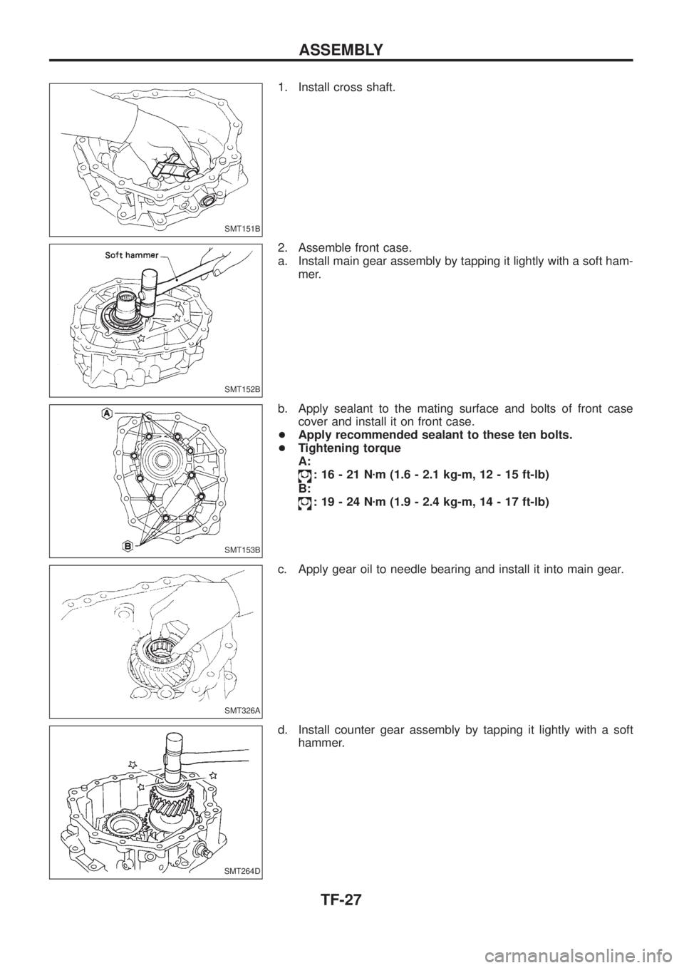
1. Install cross shaft.
2. Assemble front case.
a. Install main gear assembly by tapping it lightly with a soft ham-
mer.
b. Apply sealant to the mating surface and bolts of front case
cover and install it on front case.
+Apply recommended sealant to these ten bolts.
+Tightening torque
A:
:16-21Nzm (1.6 - 2.1 kg-m, 12 - 15 ft-lb)
B:
:19-24Nzm (1.9 - 2.4 kg-m, 14 - 17 ft-lb)
c. Apply gear oil to needle bearing and install it into main gear.
d. Install counter gear assembly by tapping it lightly with a soft
hammer.
SMT151B
SMT152B
SMT153B
SMT326A
SMT264D
ASSEMBLY
TF-27