ECO mode NISSAN PATROL 2006 Service Manual
[x] Cancel search | Manufacturer: NISSAN, Model Year: 2006, Model line: PATROL, Model: NISSAN PATROL 2006Pages: 1226, PDF Size: 37.18 MB
Page 2 of 1226
FOREWORD
This manual contains maintenance and repair procedures for NISSAN
PATROL GR,modelY61 series.
In order to assure your safety and the efficient functioning of the vehicle,
this manual should be read thoroughly. It is especially important that the
PRECAUTIONS in the GI section be completely understood before starting
any repair task.
All information in this manual is based on the latest product information
at the time of publication. The right is reserved to make changes in speci-
®cations and methods at any time without notice.
IMPORTANT SAFETY NOTICE
The proper performance of service is essential for both the safety of the
technician and the efficient functioning of the vehicle.
The service methods in this Service Manual are described in such a man-
ner that the service may be performed safely and accurately.
Service varies with the procedures used, the skills of the technician and the
tools and parts available. Accordingly, anyone using service procedures,
tools or parts which are not speci®cally recommended by NISSAN must
®rst completely satisfy himself that neither his safety nor the vehicle's
safety will be jeopardized by the service method selected.
NISSAN EUROPE S.A.S.
Service Engineering SectionParis, France
Page 10 of 1226
REMOVAL
CAUTION:
+Be careful not to splash brake ¯uid on painted areas; it
may cause paint damage. If brake ¯uid is splashed on
painted areas, wash it away with water immediately.
+ All hoses must be free from excessive bending, twisting
and pulling.
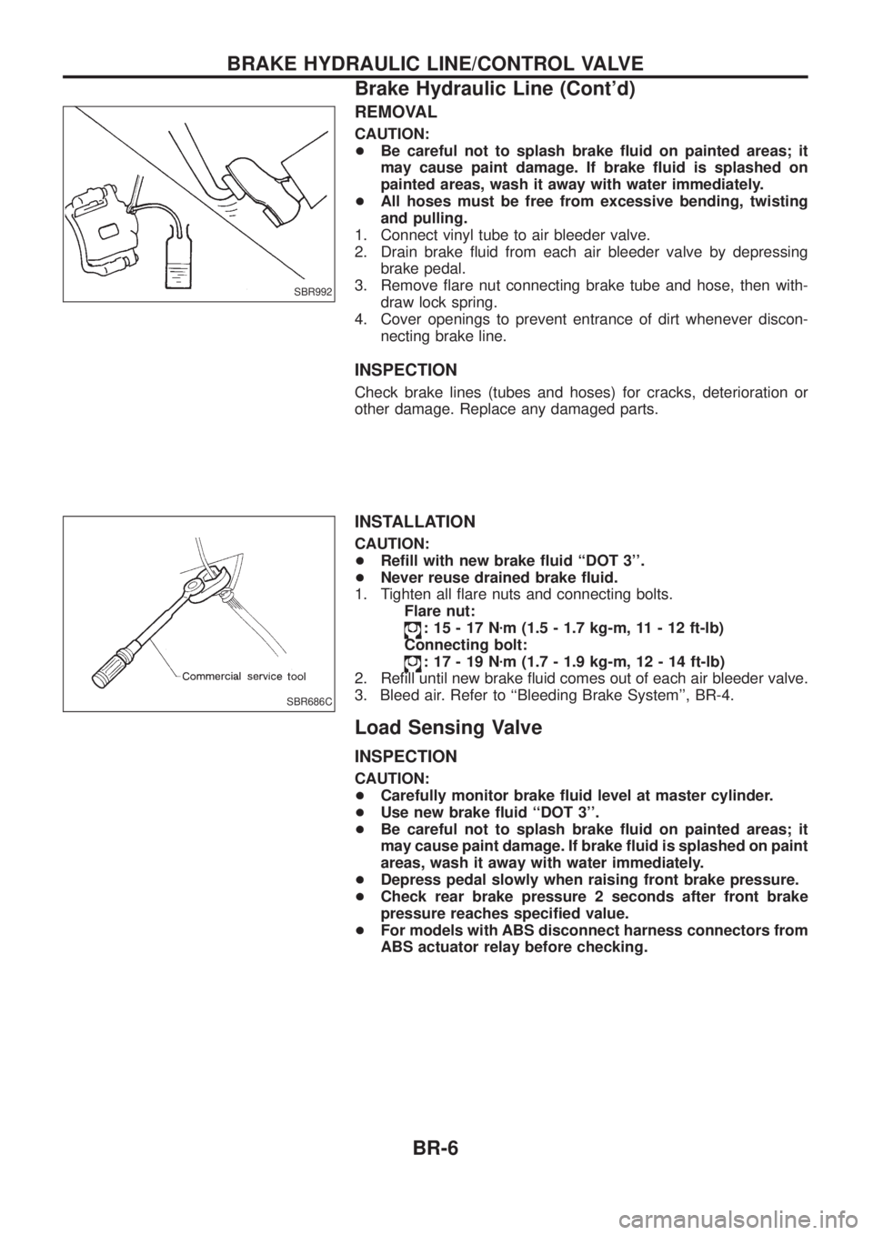
1. Connect vinyl tube to air bleeder valve.
2. Drain brake ¯uid from each air bleeder valve by depressing brake pedal.
3. Remove ¯are nut connecting brake tube and hose, then with- draw lock spring.
4. Cover openings to prevent entrance of dirt whenever discon- necting brake line.
INSPECTION
Check brake lines (tubes and hoses) for cracks, deterioration or
other damage. Replace any damaged parts.
INSTALLATION
CAUTION:
+Re®ll with new brake ¯uid ``DOT 3''.
+ Never reuse drained brake ¯uid.
1. Tighten all ¯are nuts and connecting bolts. Flare nut:
:15-17N zm (1.5 - 1.7 kg-m, 11 - 12 ft-lb)
Connecting bolt:
:17-19N zm (1.7 - 1.9 kg-m, 12 - 14 ft-lb)
2. Re®ll until new brake ¯uid comes out of each air bleeder valve.
3. Bleed air. Refer to ``Bleeding Brake System'', BR-4.
Load Sensing Valve
INSPECTION
CAUTION:
+ Carefully monitor brake ¯uid level at master cylinder.
+ Use new brake ¯uid ``DOT 3''.
+ Be careful not to splash brake ¯uid on painted areas; it
may cause paint damage. If brake ¯uid is splashed on paint
areas, wash it away with water immediately.
+ Depress pedal slowly when raising front brake pressure.
+ Check rear brake pressure 2 seconds after front brake
pressure reaches speci®ed value.
+ For models with ABS disconnect harness connectors from
ABS actuator relay before checking.
SBR992
SBR686C
BRAKE HYDRAULIC LINE/CONTROL VALVE
Brake Hydraulic Line (Cont'd)
BR-6
Page 17 of 1226
Disassembly
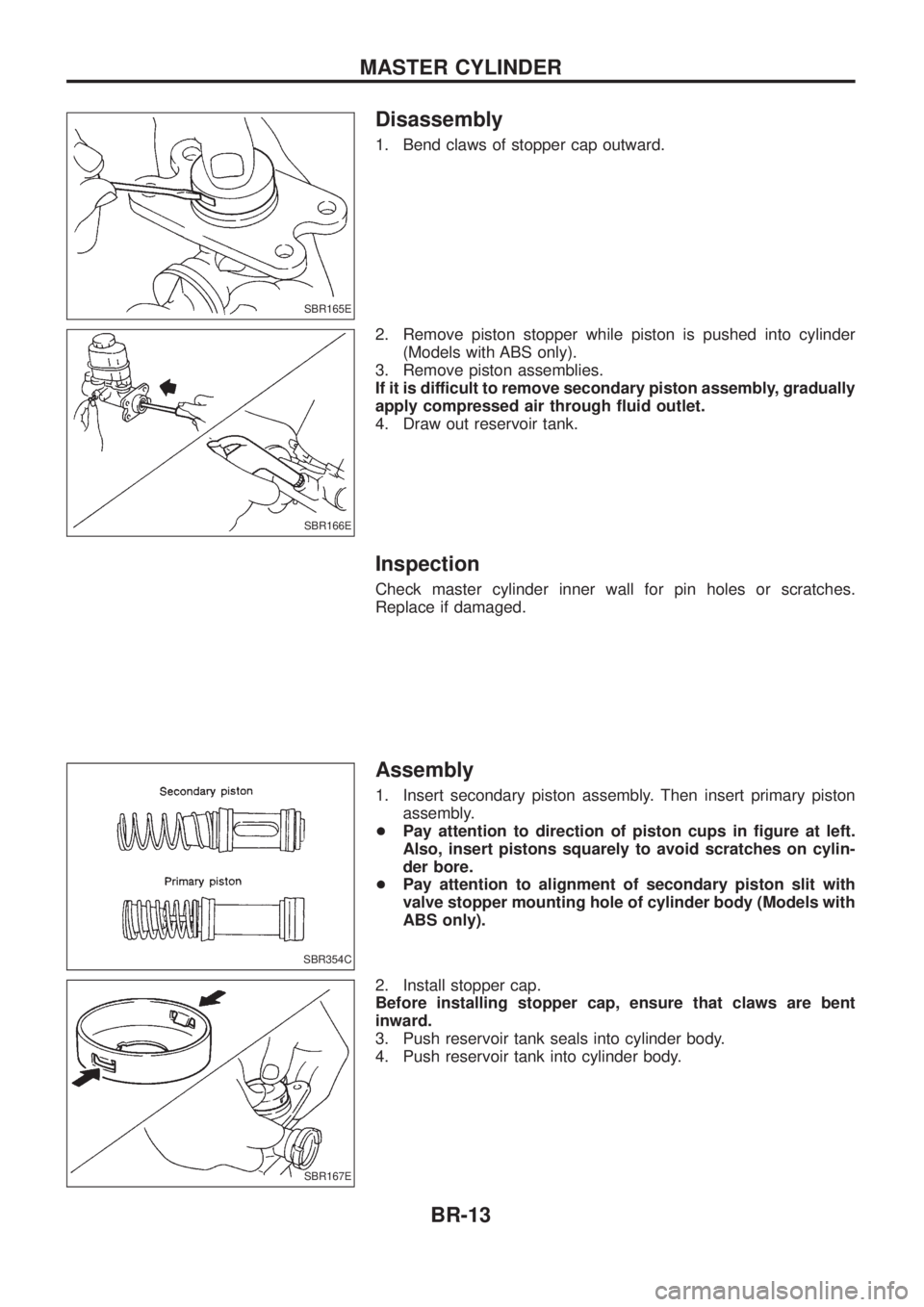
1. Bend claws of stopper cap outward.
2. Remove piston stopper while piston is pushed into cylinder(Models with ABS only).
3. Remove piston assemblies.
If it is difficult to remove secondary piston assembly, gradually
apply compressed air through ¯uid outlet.
4. Draw out reservoir tank.
Inspection
Check master cylinder inner wall for pin holes or scratches.
Replace if damaged.
Assembly
1. Insert secondary piston assembly. Then insert primary piston assembly.
+ Pay attention to direction of piston cups in ®gure at left.
Also, insert pistons squarely to avoid scratches on cylin-
der bore.
+ Pay attention to alignment of secondary piston slit with
valve stopper mounting hole of cylinder body (Models with
ABS only).
2. Install stopper cap.
Before installing stopper cap, ensure that claws are bent
inward.
3. Push reservoir tank seals into cylinder body.
4. Push reservoir tank into cylinder body.
SBR165E
SBR166E
SBR354C
SBR167E
MASTER CYLINDER
BR-13
Page 51 of 1226
Self-diagnosis
FUNCTION
+When a problem occurs in the ABS, the warning lamp on the
instrument panel comes on. To start the self-diagnostic results
mode, ground the self-diagnostic (check) terminal located on
``Data Link Connector for CONSULT''. The location of the mal-
function is indicated by the warning lamp ¯ashing.
+ While DIFF-LOCK is on, anti-lock warning light ¯ashes.
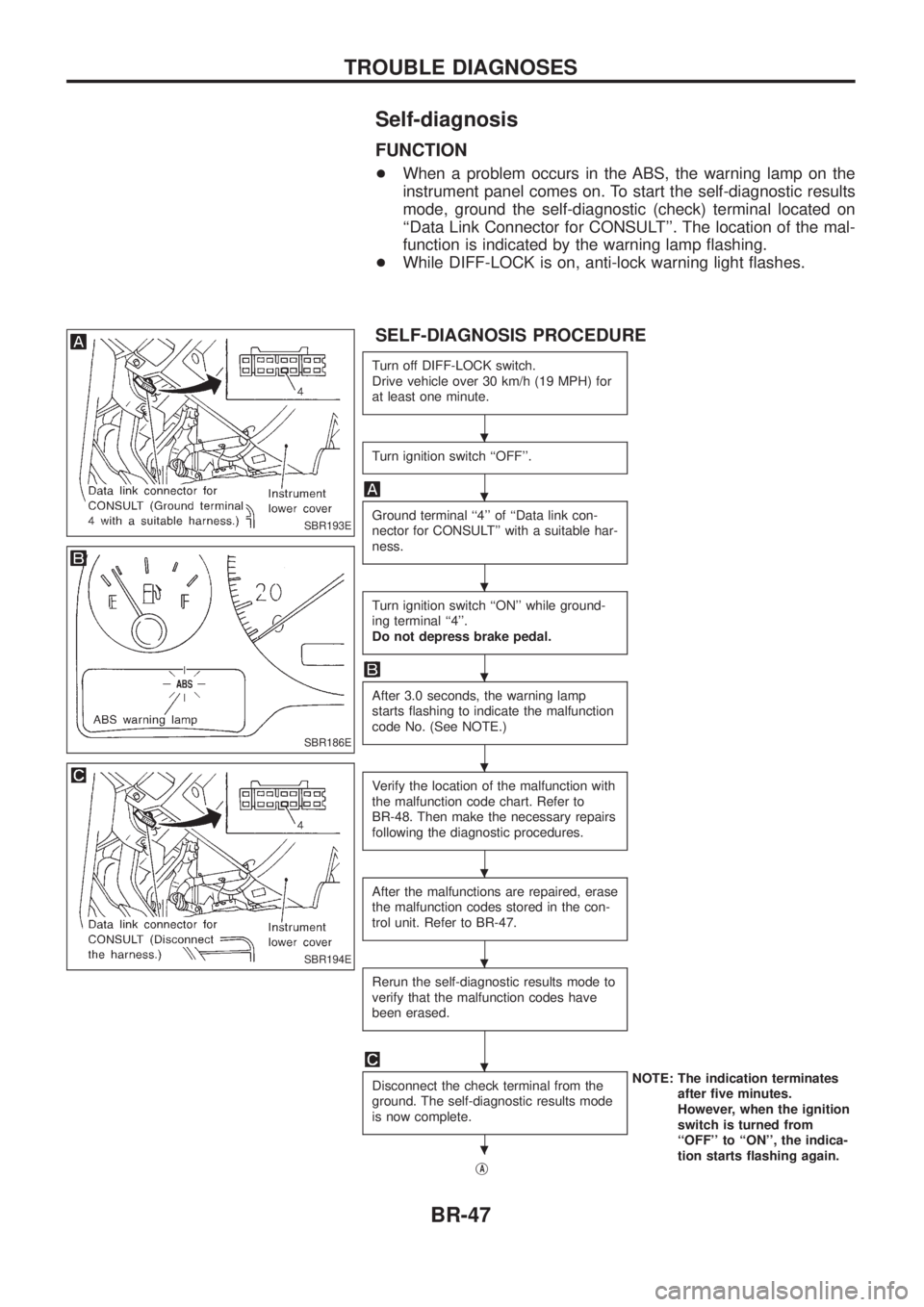
SELF-DIAGNOSIS PROCEDURE
Turn off DIFF-LOCK switch.
Drive vehicle over 30 km/h (19 MPH) for
at least one minute.
Turn ignition switch ``OFF''.
Ground terminal ``4'' of ``Data link con-
nector for CONSULT'' with a suitable har-
ness.
Turn ignition switch ``ON'' while ground-
ing terminal ``4''.
Do not depress brake pedal.
After 3.0 seconds, the warning lamp
starts ¯ashing to indicate the malfunction
code No. (See NOTE.)
Verify the location of the malfunction with
the malfunction code chart. Refer to
BR-48. Then make the necessary repairs
following the diagnostic procedures.
After the malfunctions are repaired, erase
the malfunction codes stored in the con-
trol unit. Refer to BR-47.
Rerun the self-diagnostic results mode to
verify that the malfunction codes have
been erased.
Disconnect the check terminal from the
ground. The self-diagnostic results mode
is now complete.NOTE: The indication terminates
after ®ve minutes.
However, when the ignition
switch is turned from
``OFF'' to ``ON'', the indica-
tion starts ¯ashing again.
j
A
SBR193E
SBR186E
SBR194E
.
.
.
.
.
.
.
.
.
TROUBLE DIAGNOSES
BR-47
Page 56 of 1226
![NISSAN PATROL 2006 Service Manual SELF-DIAGNOSTIC RESULTS MODE
Diagnostic item Diagnostic item is detected when ...Diagnostic
procedure
FR RH SENSOR .1
[OPEN] +
Circuit for front right wheel sensor is open.
(An abnormally high input v NISSAN PATROL 2006 Service Manual SELF-DIAGNOSTIC RESULTS MODE
Diagnostic item Diagnostic item is detected when ...Diagnostic
procedure
FR RH SENSOR .1
[OPEN] +
Circuit for front right wheel sensor is open.
(An abnormally high input v](/img/5/57368/w960_57368-55.png)
SELF-DIAGNOSTIC RESULTS MODE
Diagnostic item Diagnostic item is detected when ...Diagnostic
procedure
FR RH SENSOR .1
[OPEN] +
Circuit for front right wheel sensor is open.
(An abnormally high input voltage is entered.) 1
FR LH SENSOR .1
[OPEN] +
Circuit for front left wheel sensor is open.
(An abnormally high input voltage is entered.) 1
RR RH SENSOR .1
[OPEN] +
Circuit for rear right sensor is open.
(An abnormally high input voltage is entered.) 1
RR LH SENSOR .1
[OPEN] +
Circuit for rear left sensor is open.
(An abnormally high input voltage is entered.) 1
FR RH SENSOR .1
[SHORT] +
Circuit for front right wheel sensor is shorted.
(An abnormally low input voltage is entered.) 1
FR LH SENSOR .1
[SHORT] +
Circuit for front left wheel sensor is shorted.
(An abnormally low input voltage is entered.) 1
RR RH SENSOR .1
[SHORT] +
Circuit for rear right sensor is shorted.
(An abnormally low input voltage is entered.) 1
RR LH SENSOR .1
[SHORT] +
Circuit for rear left sensor is shorted.
(An abnormally low input voltage is entered.) 1
ABS SENSOR .1
[ABNORMAL SIGNAL] +
Teeth damage on sensor rotor or improper installation of wheel sensor.
(Abnormal wheel sensor signal is entered.) 1
FR RH IN ABS SOL
[OPEN] +
Circuit for front right inlet solenoid valve is open.
(An abnormally low output voltage is entered.) 2
FR LH IN ABS SOL
[OPEN] +
Circuit for front left inlet solenoid valve is open.
(An abnormally low output voltage is entered.) 2
RR IN ABS SOL
[OPEN] +
Circuit for rear inlet solenoid valve is open.
(An abnormally low output voltage is entered.) 2
FR RH IN ABS SOL
[SHORT] +
Circuit for front right inlet solenoid valve is shorted.
(An abnormally high output voltage is entered.) 2
FR LH IN ABS SOL
[SHORT] +
Circuit for front left inlet solenoid valve is shorted.
(An abnormally high output voltage is entered.) 2
RR IN ABS SOL
[SHORT] +
Circuit for rear inlet solenoid valve is shorted.
(An abnormally high output voltage is entered.) 2
FR RH OUT ABS SOL
[OPEN] +
Circuit for front right outlet solenoid valve is open.
(An abnormally low output voltage is entered.) 2
FR LH OUT ABS SOL
[OPEN] +
Circuit for front left outlet solenoid valve is open.
(An abnormally low output voltage is entered.) 2
RR OUT ABS SOL
[OPEN] +
Circuit for rear outlet solenoid valve is open.
(An abnormally low output voltage is entered.) 2
FR RH OUT ABS SOL
[SHORT] +
Circuit for front right outlet solenoid valve is shorted.
(An abnormally high output voltage is entered.) 2
FR LH OUT ABS SOL
[SHORT] +
Circuit for front left outlet solenoid valve is shorted.
(An abnormally high output voltage is entered.) 2
RR OUT ABS SOL
[SHORT] +
Circuit for rear outlet solenoid valve is shorted.
(An abnormally high output voltage is entered.) 2
ABS ACTUATOR RELAY
[ABNORMAL] +
Actuator solenoid valve relay is ON, even if control unit sends off signal.
+ Actuator solenoid valve relay is OFF, even if control unit sends on signal. 2
ABS MOTOR RELAY
[ABNORMAL] +
Circuit for ABS motor relay is open or shorted.
+ Circuit for actuator motor is open or shorted.
+ Actuator motor relay is stuck. 3
BATTERY VOLT
[VB-LOW] +
Power source voltage supplied to ABS control unit is abnormally low. 4
CONTROL UNIT +Function of calculation in ABS control unit has failed. 6
G-SENSOR
[ABNORMAL] +
G sensor circuit is open or shorted. 5
. 1: If one or more wheels spin on a rough or slippery road for 40 seconds or more, the ABS warning lamp will illuminate. This does
not indicate a malfunction. Only in the case of the short-circuit (Code Nos. 26, 22, 32 and 36), after repair the ABS warning
lamp also illuminates when the ignition switch is turned ``ON''. In this case, drive the vehicle at speeds greater than 30 km/h (19
MPH) for approximately 1 minute as speci®ed in ``SELF-DIAGNOSIS PROCEDURE'', BR-47. Check to ensure that the ABS
warning lamp goes out while the vehicle is being driven.
TROUBLE DIAGNOSES
CONSULT Inspection Procedure (Cont'd)
BR-52
Page 59 of 1226
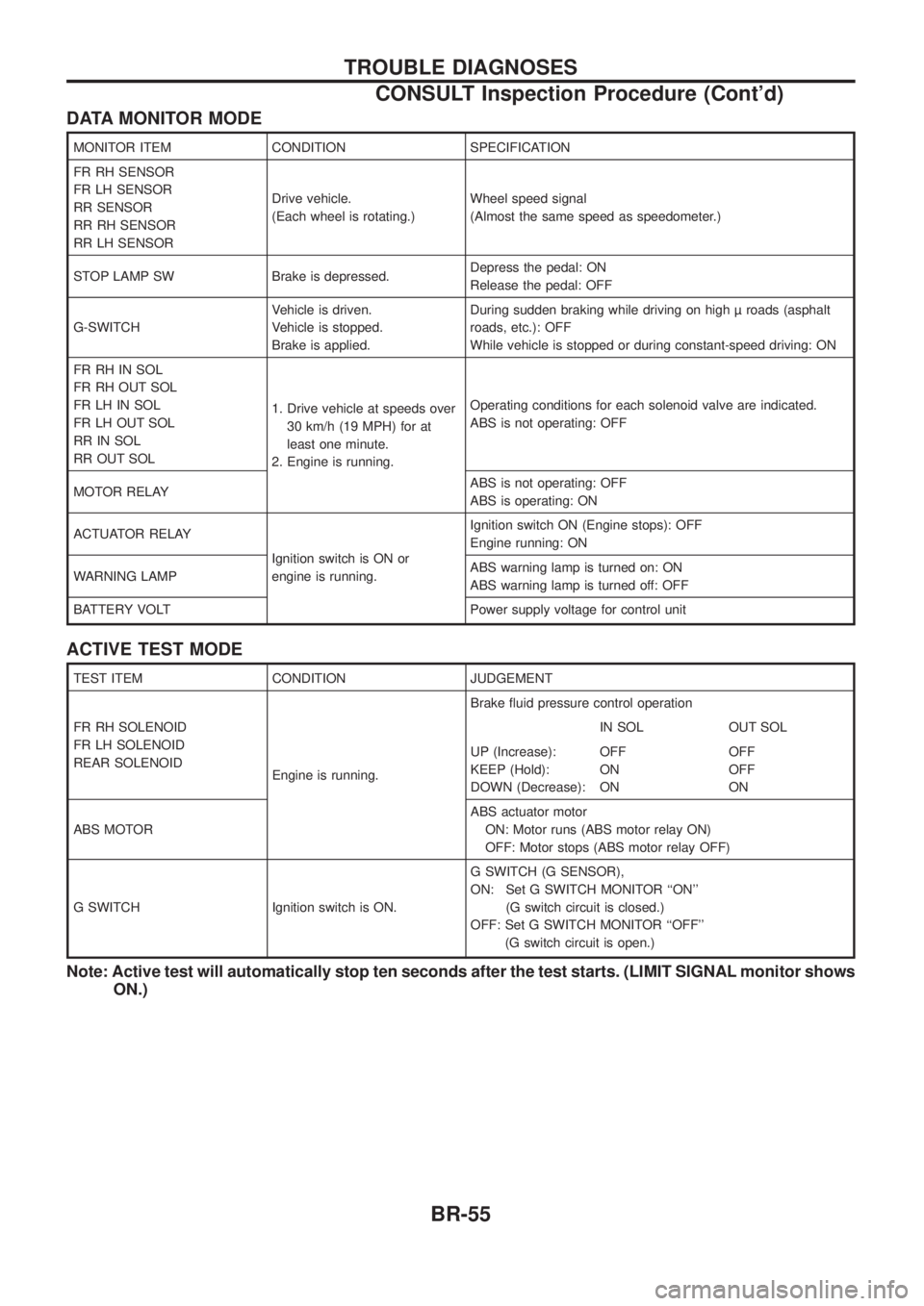
DATA MONITOR MODE
MONITOR ITEM CONDITION SPECIFICATION
FR RH SENSOR
FR LH SENSOR
RR SENSOR
RR RH SENSOR
RR LH SENSORDrive vehicle.
(Each wheel is rotating.)
Wheel speed signal
(Almost the same speed as speedometer.)
STOP LAMP SW Brake is depressed. Depress the pedal: ON
Release the pedal: OFF
G-SWITCH Vehicle is driven.
Vehicle is stopped.
Brake is applied.During sudden braking while driving on high roads (asphalt
roads, etc.): OFF
While vehicle is stopped or during constant-speed driving: ON
FR RH IN SOL
FR RH OUT SOL
FR LH IN SOL
FR LH OUT SOL
RR IN SOL
RR OUT SOL 1. Drive vehicle at speeds over
30 km/h (19 MPH) for at
least one minute.
2. Engine is running. Operating conditions for each solenoid valve are indicated.
ABS is not operating: OFF
MOTOR RELAY ABS is not operating: OFF
ABS is operating: ON
ACTUATOR RELAY Ignition switch is ON or
engine is running.Ignition switch ON (Engine stops): OFF
Engine running: ON
WARNING LAMP ABS warning lamp is turned on: ON
ABS warning lamp is turned off: OFF
BATTERY VOLT Power supply voltage for control unit
ACTIVE TEST MODE
TEST ITEM CONDITION JUDGEMENT
FR RH SOLENOID
FR LH SOLENOID
REAR SOLENOID Engine is running.Brake ¯uid pressure control operation
IN SOL OUT SOL
UP (Increase):
KEEP (Hold):
DOWN (Decrease): OFF
ON
ONOFF
OFF
ON
ABS MOTOR ABS actuator motor
ON: Motor runs (ABS motor relay ON)
OFF: Motor stops (ABS motor relay OFF)
G SWITCH Ignition switch is ON. G SWITCH (G SENSOR),
ON: Set G SWITCH MONITOR ``ON''
(G switch circuit is closed.)
OFF: Set G SWITCH MONITOR ``OFF'' (G switch circuit is open.)
Note: Active test will automatically stop ten seconds after the test starts. (LIMIT SIGNAL monitor shows ON.)
TROUBLE DIAGNOSES
CONSULT Inspection Procedure (Cont'd)
BR-55
Page 76 of 1226
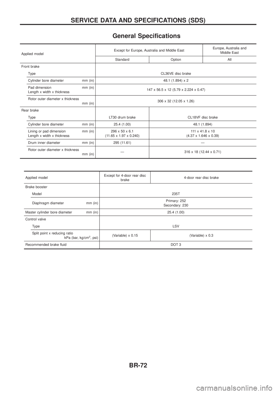
General Speci®cations
Applied modelExcept for Europe, Australia and Middle East
Europe, Australia and
Middle East
Standard Option All
Front brake Type CL36VE disc brake
Cylinder bore diameter mm (in) 48.1 (1.894) x 2
Pad dimension mm (in)
Length x width x thickness 147 x 56.5 x 12 (5.79 x 2.224 x 0.47)
Rotor outer diameter x thickness mm (in) 306 x 32 (12.05 x 1.26)
Rear brake Type LT30 drum brake CL18VF disc brake
Cylinder bore diameter mm (in) 25.4 (1.00) 48.1 (1.894)
Lining or pad dimension mm (in)
Length x width x thickness 296x50x6.1
(11.65 x 1.97 x 0.240) 111x41.8x10
(4.37 x 1.646 x 0.39)
Drum inner diameter mm (in) 295 (11.61) Ð
Rotor outer diameter x thickness mm (in)Ð 316 x 18 (12.44 x 0.71)
Applied model Except for 4-door rear disc
brake 4-door rear disc brake
Brake booster Model 235T
Diaphragm diameter mm (in) Primary: 252
Secondary: 230
Master cylinder bore diameter mm (in) 25.4 (1.00)
Control valve Type LSV
Split point x reducing ratio kPa (bar, kg/cm
2, psi)(Variable) x 0.15 (Variable) x 0.3
Recommended brake ¯uid DOT 3
SERVICE DATA AND SPECIFICATIONS (SDS)
BR-72
Page 146 of 1226
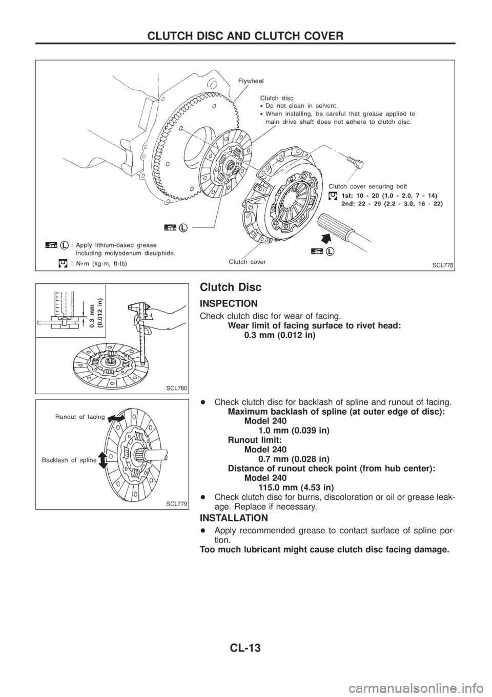
Clutch Disc
INSPECTION
Check clutch disc for wear of facing.
Wear limit of facing surface to rivet head:
0.3 mm (0.012 in)
+Check clutch disc for backlash of spline and runout of facing.
Maximum backlash of spline (at outer edge of disc):
Model 240
1.0 mm (0.039 in)
Runout limit:
Model 240
0.7 mm (0.028 in)
Distance of runout check point (from hub center):
Model 240
115.0 mm (4.53 in)
+Check clutch disc for burns, discoloration or oil or grease leak-
age. Replace if necessary.
INSTALLATION
+Apply recommended grease to contact surface of spline por-
tion.
Too much lubricant might cause clutch disc facing damage.
SCL778
SCL780
SCL779
CLUTCH DISC AND CLUTCH COVER
CL-13
Page 150 of 1226
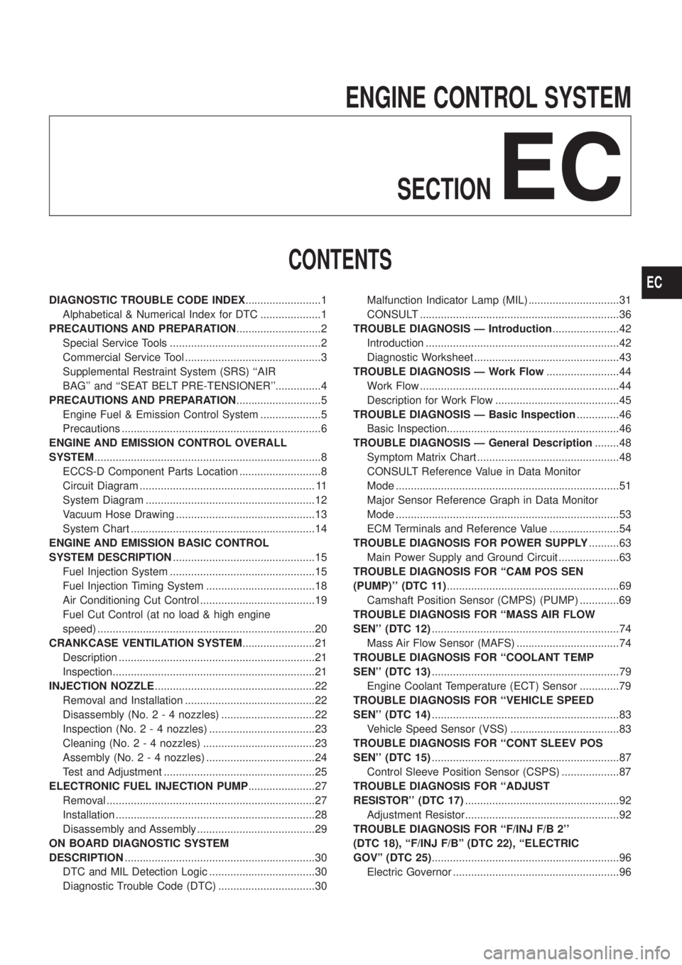
ENGINE CONTROL SYSTEMSECTION
EC
CONTENTS
DIAGNOSTIC TROUBLE CODE INDEX .........................1
Alphabetical & Numerical Index for DTC ....................1
PRECAUTIONS AND PREPARATION ............................2
Special Service Tools ..................................................2
Commercial Service Tool .............................................3
Supplemental Restraint System (SRS) ``AIR
BAG'' and ``SEAT BELT PRE-TENSIONER''...............4
PRECAUTIONS AND PREPARATION ............................5
Engine Fuel & Emission Control System ....................5
Precautions ..................................................................6
ENGINE AND EMISSION CONTROL OVERALL
SYSTEM ........................................................................\
...8
ECCS-D Component Parts Location ...........................8
Circuit Diagram .......................................................... 11
System Diagram ........................................................12
Vacuum Hose Drawing ..............................................13
System Chart .............................................................14
ENGINE AND EMISSION BASIC CONTROL
SYSTEM DESCRIPTION ...............................................15
Fuel Injection System ................................................15
Fuel Injection Timing System ....................................18
Air Conditioning Cut Control ......................................19
Fuel Cut Control (at no load & high engine
speed) ........................................................................\
20
CRANKCASE VENTILATION SYSTEM ........................21
Description .................................................................21
Inspection...................................................................21
INJECTION NOZZLE .....................................................22
Removal and Installation ...........................................22
Disassembly (No. 2 - 4 nozzles) ...............................22
Inspection (No. 2 - 4 nozzles) ...................................23
Cleaning (No. 2 - 4 nozzles) .....................................23
Assembly (No. 2 - 4 nozzles) ....................................24
Test and Adjustment ..................................................25
ELECTRONIC FUEL INJECTION PUMP ......................27
Removal .....................................................................27
Installation ..................................................................28
Disassembly and Assembly .......................................29
ON BOARD DIAGNOSTIC SYSTEM
DESCRIPTION ...............................................................30
DTC and MIL Detection Logic ...................................30
Diagnostic Trouble Code (DTC) ................................30 Malfunction Indicator Lamp (MIL) ..............................31
CONSULT ..................................................................36
TROUBLE DIAGNOSIS Ð Introduction ......................42
Introduction ................................................................42
Diagnostic Worksheet ................................................43
TROUBLE DIAGNOSIS Ð Work Flow ........................44
Work Flow ..................................................................44
Description for Work Flow .........................................45
TROUBLE DIAGNOSIS Ð Basic Inspection ..............46
Basic Inspection.........................................................46
TROUBLE DIAGNOSIS Ð General Description ........48
Symptom Matrix Chart ...............................................48
CONSULT Reference Value in Data Monitor
Mode ........................................................................\
..51
Major Sensor Reference Graph in Data Monitor
Mode ........................................................................\
..53
ECM Terminals and Reference Value .......................54
TROUBLEDIAGNOSISFORPOWERSUPPLY ..........63
MainPowerSupplyandGroundCircuit....................63
TROUBLE DIAGNOSIS FOR ``CAM POS SEN
(PUMP)''(DTC11) .........................................................69
CamshaftPositionSensor(CMPS)(PUMP).............69
TROUBLEDIAGNOSISFOR``MASSAIRFLOW
SEN''(DTC12) ..............................................................74
MassAirFlowSensor(MAFS)..................................74
TROUBLEDIAGNOSISFOR``COOLANTTEMP
SEN''(DTC13) ..............................................................79
EngineCoolantTemperature(ECT)Sensor.............79
TROUBLEDIAGNOSISFOR``VEHICLESPEED
SEN''(DTC14) ..............................................................83
VehicleSpeedSensor(VSS)....................................83
TROUBLEDIAGNOSISFOR``CONTSLEEVPOS
SEN''(DTC15) ..............................................................87
ControlSleevePositionSensor(CSPS)...................87
TROUBLEDIAGNOSISFOR``ADJUST
RESISTOR''(DTC17) ...................................................92
AdjustmentResistor...................................................92
TROUBLEDIAGNOSISFOR``F/INJF/B2''
(DTC18),``F/INJF/B''(DTC22),``ELECTRIC
GOV''(DTC25) ..............................................................96
ElectricGovernor.......................................................96
EC
Page 166 of 1226
Fuel Injection System
SYSTEM DESCRIPTION
Three types of fuel injection control are provided to accommodate engine operating conditions; normal control,
idle control and start control. The ECM determines the appropriate fuel injection control. Under each control,
the amount of fuel injected is compensated to improve engine performance. The ECM performs duty control
on the electric governor (built into the fuel injection pump) according to sensor signals to compensate the
amount of fuel injected to the preset value.
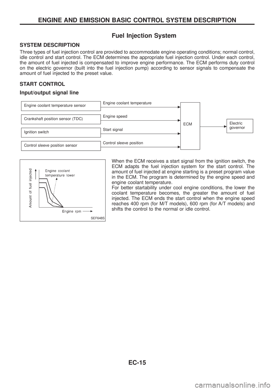
START CONTROL
Input/output signal line
Engine coolant temperature sensorcEngine coolant temperature
ECM
cElectric
governorCrankshaft position sensor (TDC)cEngine speed
Ignition switch
cStart signal
Control sleeve position sensor
cControl sleeve position
When the ECM receives a start signal from the ignition switch, the
ECM adapts the fuel injection system for the start control. The
amount of fuel injected at engine starting is a preset program value
in the ECM. The program is determined by the engine speed and
engine coolant temperature.
For better startability under cool engine conditions, the lower the
coolant temperature becomes, the greater the amount of fuel
injected. The ECM ends the start control when the engine speed
reaches 400 rpm (for M/T models), 600 rpm (for A/T models) and
shifts the control to the normal or idle control.
SEF648S
ENGINE AND EMISSION BASIC CONTROL SYSTEM DESCRIPTION
EC-15