fuel NISSAN PATROL 2006 Repair Manual
[x] Cancel search | Manufacturer: NISSAN, Model Year: 2006, Model line: PATROL, Model: NISSAN PATROL 2006Pages: 1226, PDF Size: 37.18 MB
Page 289 of 1226

COMPONENT INSPECTION
Fuel temperature sensor
Wait until fuel temperature sensor reaches room temperature.
Check resistance as shown in the ®gure.
Temperature ÉC (ÉF) Resistance kW
20 (68) 2.306 - 2.568
60 (140) 0.538 - 0.624
80 (176) 0.289 - 0.344
If NG, take proper action.SEF693V
SEF012P
TROUBLE DIAGNOSIS FOR ``FUEL TEMP SENSOR'' (DTC 42)
Fuel Temperature Sensor (FTS) (Cont'd)
EC-138
Page 290 of 1226

Accelerator Position Sensor
The accelerator position sensor is installed on the upper end of the
accelerator pedal assembly. The sensor detects the accelerator
position and sends a signal to the ECM. The ECM uses the signal
to determine the amount of fuel to be injected.
CONSULT REFERENCE VALUE IN DATA MONITOR MODE
Remarks: Speci®cation data are reference values.
MONITOR ITEM CONDITION SPECIFICATION
ACCEL POS SEN+Ignition switch: ON
(Engine stopped)Accelerator pedal: released 0.40 - 0.60V
Accelerator pedal: depressed Approx. 4.0V
ECM TERMINALS AND REFERENCE VALUE
Remarks: Speci®cation data are reference values and are measured between each terminal andV43(ECCS
ground) with a voltmeter.
TER-
MINAL
NO.WIRE
COLORITEM CONDITIONDATA
(DC Voltage and Pulse
Signal)
23 WAccelerator position sen-
sorIgnition switch ``ON''
Accelerator pedal fully released0.4 - 0.6V
Ignition switch ``ON''
Accelerator pedal fully depressedApproximately 4.3V
48 G/RAccelerator position sen-
sor power supplyIgnition switch ``ON''
Approximately 5V
51 L/WAccelerator position sen-
sor groundEngine is running.
(Warm-up condition)
Idle speedApproximately 0V
SEF861SA
TROUBLE DIAGNOSIS FOR ``ACCEL POS SENSOR'' (DTC 43)
EC-139
Page 295 of 1226

Crankshaft Position Sensor (TDC)
The crankshaft position sensor (TDC) monitors engine speed by
means of signals from the sensing plate (with two protrusions)
installed to the crankshaft pulley. The datum signal output is
detected at ATDC 70É and sent to the ECM. The sensor signal is
used for fuel injection control and fuel injection timing control.
CONSULT REFERENCE VALUE IN DATA MONITOR MODE
Remarks: Speci®cation data are reference values.
MONITOR ITEM CONDITION SPECIFICATION
CKPSzRPM (TDC)+Tachometer: Connect
+Run engine and compare tachometer indication with the CONSULT
value.Almost the same speed as the
CONSULT value.
ECM TERMINALS AND REFERENCE VALUE
Remarks: Speci®cation data are reference values and are measured between each terminal andV43(ECCS
ground) with a voltmeter.
TER-
MINAL
NO.WIRE
COLORITEM CONDITIONDATA
(DC Voltage and Pulse
Signal)
40
44LCrankshaft position sensor
(TDC)Engine is running.
(Warm-up condition)
Idle speedApproximately 0V
SEF720V
Engine is running.(Warm-up condition)
Engine speed is 2,000 rpm.Approximately 0V
SEF721V
47
52B/WCrankshaft position sensor
(TDC) groundEngine is running.(Warm-up condition)
Idle speedApproximately 0V
ON BOARD DIAGNOSIS LOGIC
Diagnostic
Trouble Code
No.Malfunction is detected when ....Check Items
(Possible Cause)
47+An improper signal from the sensor is detected by
ECM during engine running and cranking.+Harness or connectors
(The sensor circuit is open.)
+Crankshaft position sensor (TDC)
SEF615S
TROUBLE DIAGNOSIS FOR ``CRANK POS SEN (TDC)'' (DTC 47)
EC-144
Page 300 of 1226
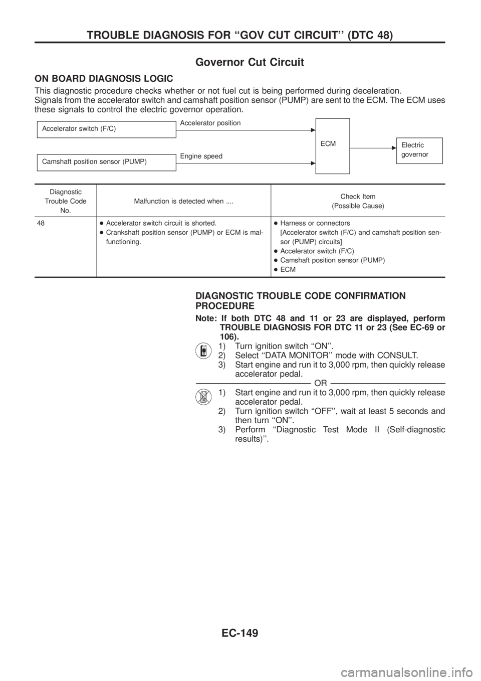
Governor Cut Circuit
ON BOARD DIAGNOSIS LOGIC
This diagnostic procedure checks whether or not fuel cut is being performed during deceleration.
Signals from the accelerator switch and camshaft position sensor (PUMP) are sent to the ECM. The ECM uses
these signals to control the electric governor operation.
Accelerator switch (F/C)cAccelerator position
ECM
cElectric
governor
Camshaft position sensor (PUMP)cEngine speed
Diagnostic
Trouble Code
No.Malfunction is detected when ....Check Item
(Possible Cause)
48+Accelerator switch circuit is shorted.
+Crankshaft position sensor (PUMP) or ECM is mal-
functioning.+Harness or connectors
[Accelerator switch (F/C) and camshaft position sen-
sor (PUMP) circuits]
+Accelerator switch (F/C)
+Camshaft position sensor (PUMP)
+ECM
DIAGNOSTIC TROUBLE CODE CONFIRMATION
PROCEDURE
Note: If both DTC 48 and 11 or 23 are displayed, perform
TROUBLE DIAGNOSIS FOR DTC 11 or 23 (See EC-69 or
106).
1) Turn ignition switch ``ON''.
2) Select ``DATA MONITOR'' mode with CONSULT.
3) Start engine and run it to 3,000 rpm, then quickly release
accelerator pedal.
-------------------------------------------------------------------------------------------------------------------------------------------------------------------------------------------------------------------------------------------------------OR-------------------------------------------------------------------------------------------------------------------------------------------------------------------------------------------------------------------------------------------------------
1) Start engine and run it to 3,000 rpm, then quickly release
accelerator pedal.
2) Turn ignition switch ``OFF'', wait at least 5 seconds and
then turn ``ON''.
3) Perform ``Diagnostic Test Mode II (Self-diagnostic
results)''.
TROUBLE DIAGNOSIS FOR ``GOV CUT CIRCUIT'' (DTC 48)
EC-149
Page 304 of 1226
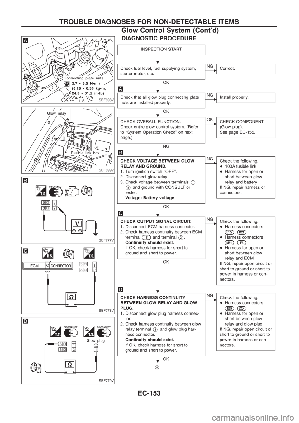
DIAGNOSTIC PROCEDURE
INSPECTION START
Check fuel level, fuel supplying system,
starter motor, etc.
OK
cNG
Correct.
Check that all glow plug connecting plate
nuts are installed properly.
OK
cNG
Install properly.
CHECK OVERALL FUNCTION.
Check entire glow control system. (Refer
to ``System Operation Check'' on next
page.)
NG
cOK
CHECK COMPONENT
(Glow plug).
See page EC-155.
CHECK VOLTAGE BETWEEN GLOW
RELAY AND GROUND.
1. Turn ignition switch ``OFF''.
2. Disconnect glow relay.
3. Check voltage between terminals
V1,
V3and ground with CONSULT or
tester.
Voltage: Battery voltage
OK
cNG
Check the following.
+100A fusible link
+Harness for open or
short between glow
relay and battery
If NG, repair harness or
connectors.
CHECK OUTPUT SIGNAL CIRCUIT.
1. Disconnect ECM harness connector.
2. Check harness continuity between ECM
terminal
111and terminalV2.
Continuity should exist.
If OK, check harness for short to
ground and short to power.
OK
cNG
Check the following.
+Harness connectors
E127,M21
+Harness connectors
M51,F6
+Harness for open or
short between glow
relay and ECM
If NG, repair open circuit or
short to ground or short to
power in harness or con-
nectors.
CHECK HARNESS CONTINUITY
BETWEEN GLOW RELAY AND GLOW
PLUG.
1. Disconnect glow plug harness connec-
tor.
2. Check harness continuity between glow
relay terminal
V5and glow plug har-
ness connector.
Continuity should exist.
If OK, check harness for short to
ground and short to power.
OK
cNG
Check the following.
+Harness connectors
E65,E204
+Harness for open or
short between glow
relay and glow plug
If NG, repair open circuit or
short to ground or short to
power in harness or con-
nectors.
jA
SEF698V
SEF699V
SEF777V
SEF778V
SEF779V
.
.
.
.
.
.
.
TROUBLE DIAGNOSES FOR NON-DETECTABLE ITEMS
Glow Control System (Cont'd)
EC-153
Page 341 of 1226

ADJUSTMENT RESISTOR
Resistance [at 25ÉC (77ÉF)] kW0.2 - 15.0
INJECTION TIMING CONTROL VALVE
Resistance [at 20ÉC (68ÉF)]WApproximately 11
ELECTRIC GOVERNOR
Resistance [at 23ÉC (73ÉF)]W0.68
CRANKSHAFT POSITION SENSOR (TDC)
Resistance [at 25ÉC (77ÉF)] kWApproximately 0.8 - 1.2
GLOW PLUG
Resistance [at 25ÉC (77ÉF)]W0.8
ACCELERATOR POSITION SENSOR
Throttle valve conditionsResistance kW
[at 25ÉC (77ÉF)]
Completely closed Approximately 0.5
Partially open 0.5 - 4
Completely open Approximately 4
FUEL TEMPERATURE SENSOR
Temperature ÉC (ÉF) Resistance kW
þ20 (þ4) 13.67 - 16.37
20 (68) 2.306 - 2.568
60 (140) 0.538 - 0.624
80 (176) 0.289 - 0.344
SERVICE DATA AND SPECIFICATIONS (SDS)
Inspection and Adjustment (Cont'd)
EC-190
Page 345 of 1226
BULB SPECIFICATIONS............................................314
Headlamp.................................................................314
Exterior Lamp ..........................................................314
Interior Lamp............................................................314
WIRING DIAGRAM CODES (CELL CODES) .............315
WIRING DIAGRAM REFERENCE CHART
ECCS, IGNITION SYSTEM ........................................................................\
................... EC SECTION
ANTI-LOCK BRAKE SYSTEM ........................................................................\
.............. BR SECTION
SRS ``AIR BAG'' ........................................................................\
.................................... RS SECT ION
HEATER AND AIR CONDITIONER ........................................................................\
...... HA SECTION
DIFFERENTIAL CARRIER ........................................................................\
.................... PD SECTION
REAR SUSPENSION ........................................................................\
............................. RA SECTION
FUEL SYSTEM ........................................................................\
....................................... FE SECT ION
Page 391 of 1226
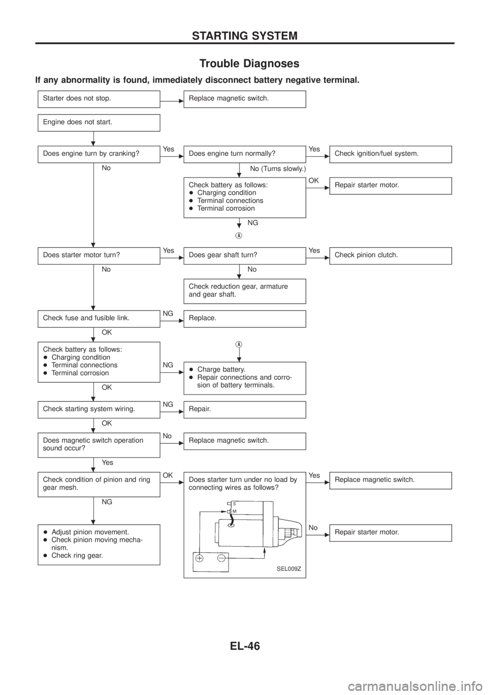
Trouble Diagnoses
If any abnormality is found, immediately disconnect battery negative terminal.
Starter does not stop.cReplace magnetic switch.
Engine does not start.
Does engine turn by cranking?
No
cYe s
Does engine turn normally?
No (Turns slowly.)
cYe s
Check ignition/fuel system.
Check battery as follows:
+Charging condition
+Terminal connections
+Terminal corrosion
NG
cOK
Repair starter motor.
jA
Does starter motor turn?
No
cYe s
Does gear shaft turn?
No
cYe s
Check pinion clutch.
Check reduction gear, armature
and gear shaft.
Check fuse and fusible link.
OK
cNG
Replace.
Check battery as follows:
+Charging condition
+Terminal connections
+Terminal corrosion
OKj
A
cNG
+Charge battery.
+Repair connections and corro-
sion of battery terminals.
Check starting system wiring.
OK
cNG
Repair.
Does magnetic switch operation
sound occur?
Ye s
cNo
Replace magnetic switch.
Check condition of pinion and ring
gear mesh.
NG
cOK
Does starter turn under no load by
connecting wires as follows?
SEL009Z
cYe s
Replace magnetic switch.
+Adjust pinion movement.
+Check pinion moving mecha-
nism.
+Check ring gear.cNo
Repair starter motor.
.
.
.
.
.
.
.
.
.
.
.
.
STARTING SYSTEM
EL-46
Page 408 of 1226
Bulb Replacement
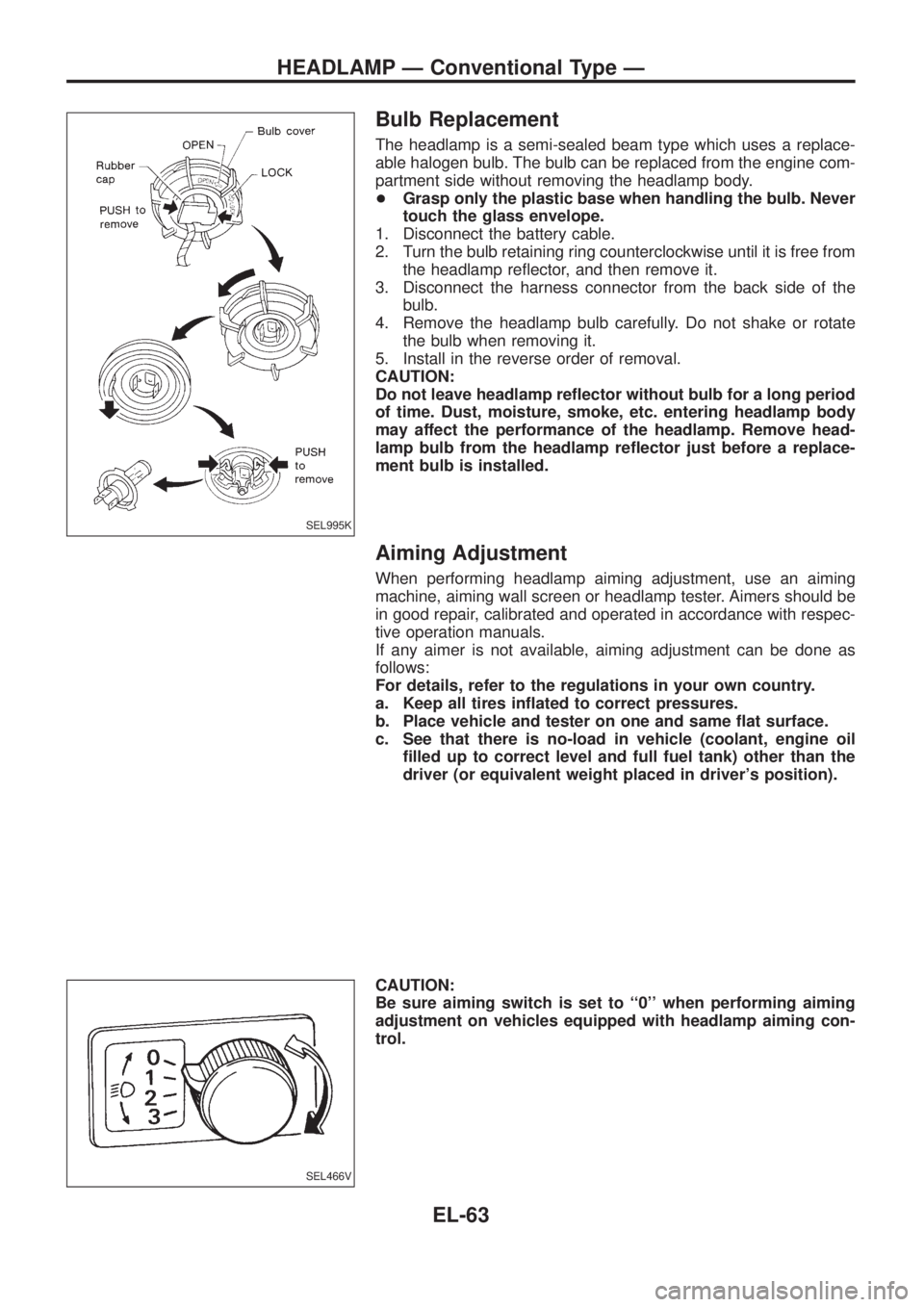
The headlamp is a semi-sealed beam type which uses a replace-
able halogen bulb. The bulb can be replaced from the engine com-
partment side without removing the headlamp body.
+Grasp only the plastic base when handling the bulb. Never
touch the glass envelope.
1. Disconnect the battery cable.
2. Turn the bulb retaining ring counterclockwise until it is free from
the headlamp re¯ector, and then remove it.
3. Disconnect the harness connector from the back side of the
bulb.
4. Remove the headlamp bulb carefully. Do not shake or rotate
the bulb when removing it.
5. Install in the reverse order of removal.
CAUTION:
Do not leave headlamp re¯ector without bulb for a long period
of time. Dust, moisture, smoke, etc. entering headlamp body
may affect the performance of the headlamp. Remove head-
lamp bulb from the headlamp re¯ector just before a replace-
ment bulb is installed.
Aiming Adjustment
When performing headlamp aiming adjustment, use an aiming
machine, aiming wall screen or headlamp tester. Aimers should be
in good repair, calibrated and operated in accordance with respec-
tive operation manuals.
If any aimer is not available, aiming adjustment can be done as
follows:
For details, refer to the regulations in your own country.
a. Keep all tires in¯ated to correct pressures.
b. Place vehicle and tester on one and same ¯at surface.
c. See that there is no-load in vehicle (coolant, engine oil
®lled up to correct level and full fuel tank) other than the
driver (or equivalent weight placed in driver's position).
CAUTION:
Be sure aiming switch is set to ``0'' when performing aiming
adjustment on vehicles equipped with headlamp aiming con-
trol.
SEL995K
SEL466V
HEADLAMP Ð Conventional Type Ð
EL-63
Page 447 of 1226
System Description
UNIFIED CONTROL METER
+Speedometer, odo/trip meter, tachometer, fuel gauge and water temperature gauge are controlled totally
by control unit combined with speedometer.
+Digital meter is adopted for odo/trip meter.*
*The record of the odo meter is kept even if the battery cable is disconnected. The record of the trip meter
is erased when the battery cable is disconnected.
+Odo/trip meter segment can be checked in diagnosis mode.
+Meter/gauge can be checked in diagnosis mode.
Note: Sub fuel gauge is not controlled by the control unit.
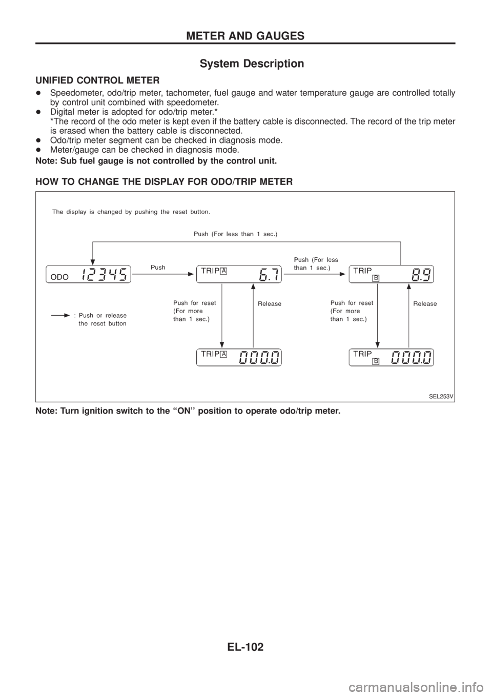
HOW TO CHANGE THE DISPLAY FOR ODO/TRIP METER
Note: Turn ignition switch to the ``ON'' position to operate odo/trip meter.
SEL253V
METER AND GAUGES
EL-102