300 NISSAN PATROL 2006 Service Manual
[x] Cancel search | Manufacturer: NISSAN, Model Year: 2006, Model line: PATROL, Model: NISSAN PATROL 2006Pages: 1226, PDF Size: 37.18 MB
Page 118 of 1226
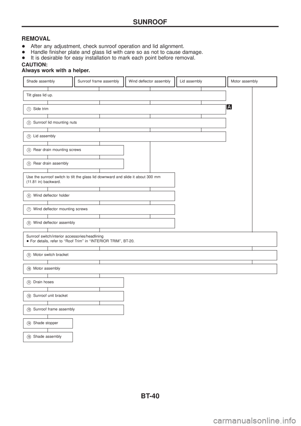
REMOVAL
+After any adjustment, check sunroof operation and lid alignment.
+Handle ®nisher plate and glass lid with care so as not to cause damage.
+It is desirable for easy installation to mark each point before removal.
CAUTION:
Always work with a helper.
Shade assemblySunroof frame assemblyWind de¯ector assemblyLid assemblyMotor assembly
Tilt glass lid up.
V1Side trim
V2Sunroof lid mounting nuts
V3Lid assembly
V4Rear drain mounting screws
V5Rear drain assembly
Use the sunroof switch to tilt the glass lid downward and slide it about 300 mm
(11.81 in) backward.
V6Wind de¯ector holder
V7Wind de¯ector mounting screws
V8Wind de¯ector assembly
Sunroof switch/interior accessories/headlining
+For details, refer to ``Roof Trim'' in ``INTERIOR TRIM'', BT-20.
V9Motor switch bracket
V10Motor assembly
V11Drain hoses
V12Sunroof unit bracket
V13Sunroof frame assembly
V14Shade stopper
V15Shade assembly
SUNROOF
BT-40
Page 134 of 1226
Precautions
+Recommended ¯uid is brake ¯uid ``DOT 3''.
+Do not reuse drained brake ¯uid.
+Be careful not to splash brake ¯uid on painted areas.
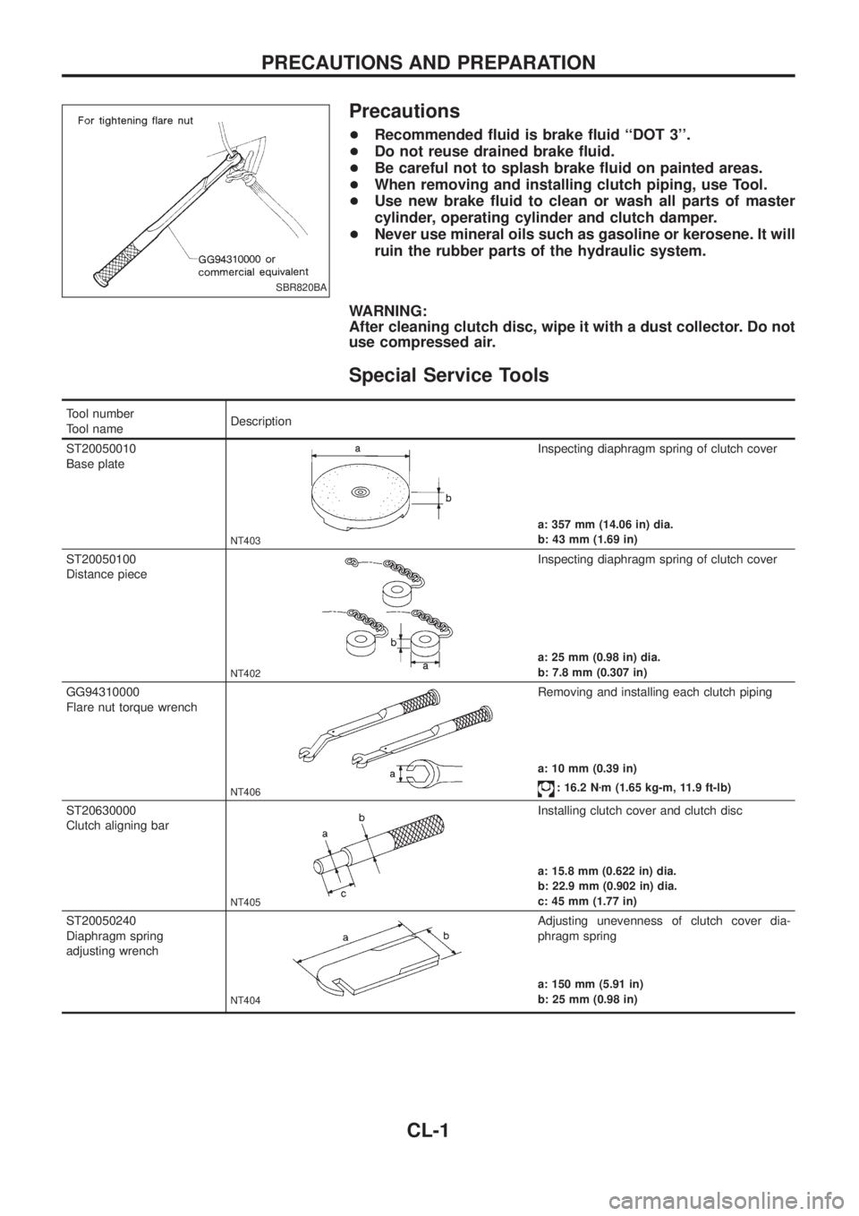
+When removing and installing clutch piping, use Tool.
+Use new brake ¯uid to clean or wash all parts of master
cylinder, operating cylinder and clutch damper.
+Never use mineral oils such as gasoline or kerosene. It will
ruin the rubber parts of the hydraulic system.
WARNING:
After cleaning clutch disc, wipe it with a dust collector. Do not
use compressed air.
Special Service Tools
Tool number
Tool nameDescription
ST20050010
Base plate
NT403
Inspecting diaphragm spring of clutch cover
a: 357 mm (14.06 in) dia.
b: 43 mm (1.69 in)
ST20050100
Distance piece
NT402
Inspecting diaphragm spring of clutch cover
a: 25 mm (0.98 in) dia.
b: 7.8 mm (0.307 in)
GG94310000
Flare nut torque wrench
NT406
Removing and installing each clutch piping
a: 10 mm (0.39 in)
: 16.2 Nzm (1.65 kg-m, 11.9 ft-lb)
ST20630000
Clutch aligning bar
NT405
Installing clutch cover and clutch disc
a: 15.8 mm (0.622 in) dia.
b: 22.9 mm (0.902 in) dia.
c: 45 mm (1.77 in)
ST20050240
Diaphragm spring
adjusting wrench
NT404
Adjusting unevenness of clutch cover dia-
phragm spring
a: 150 mm (5.91 in)
b: 25 mm (0.98 in)
SBR820BA
PRECAUTIONS AND PREPARATION
CL-1
Page 154 of 1226
Tool number
Tool nameDescription
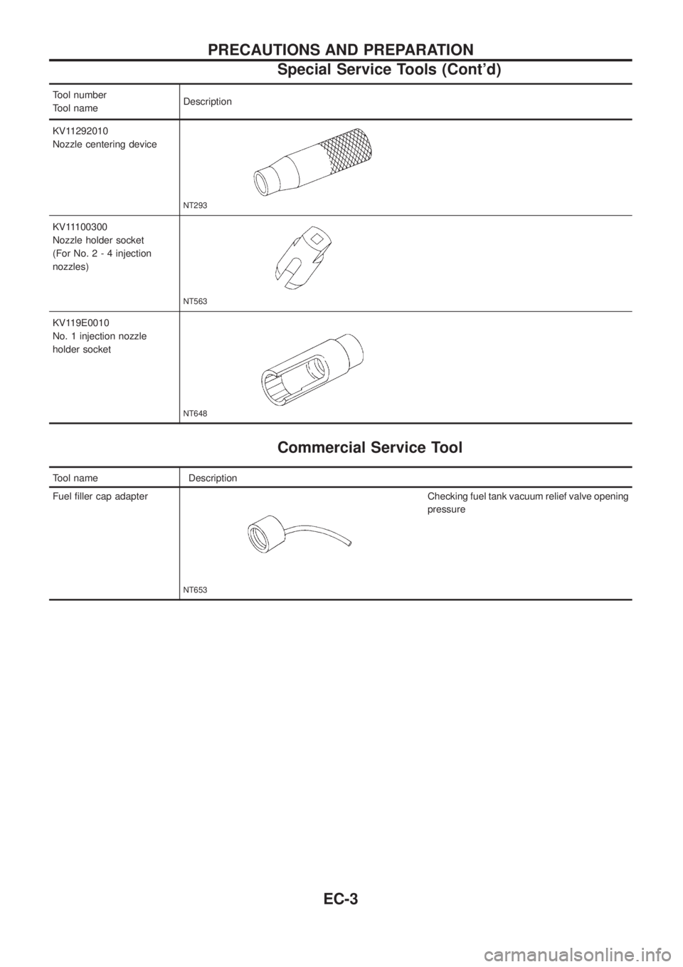
KV11292010
Nozzle centering device
NT293
KV11100300
Nozzle holder socket
(For No.2-4injection
nozzles)
NT563
KV119E0010
No. 1 injection nozzle
holder socket
NT648
Commercial Service Tool
Tool name Description
Fuel ®ller cap adapter
NT653
Checking fuel tank vacuum relief valve opening
pressure
PRECAUTIONS AND PREPARATION
Special Service Tools (Cont'd)
EC-3
Page 340 of 1226
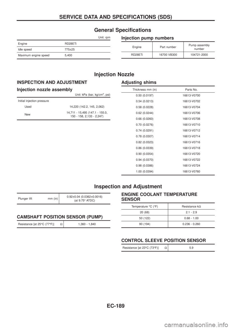
General Speci®cations
Unit: rpm
Engine RD28ETi
Idle speed 775 25
Maximum engine speed 5,400
Injection pump numbers
Engine Part numberPump assembly
number
RD28ETi 16700 VB300 104721-2000
Injection Nozzle
INSPECTION AND ADJUSTMENT
Injection nozzle assembly
Unit: kPa (bar, kg/cm2, psi)
Initial injection pressure
Used 14,220 (142.2, 145, 2,062)
New14,711 - 15,495 (147.1 - 155.0,
150 - 158, 2,133 - 2,247)
Adjusting shims
Thickness mm (in) Parts No.
0.50 (0.0197) 16613-V0700
0.54 (0.0213) 16613-V0702
0.58 (0.0228) 16613-V0704
0.62 (0.0244) 16613-V0706
0.66 (0.0260) 16613-V0708
0.70 (0.0276) 16613-V0710
0.74 (0.0291) 16613-V0712
0.78 (0.0307) 16613-V0714
0.82 (0.0323) 16613-V0716
0.86 (0.0339) 16613-V0718
0.90 (0.0354) 16613-V0720
0.94 (0.0370) 16613-V0722
0.98 (0.0386) 16613-V0724
1.00 (0.0394) 16613-V0760
Inspection and Adjustment
Plunger lift mm (in)0.92 0.04 (0.0362 0.0016)
(at 9.75É ATDC)
CAMSHAFT POSITION SENSOR (PUMP)
Resistance [at 25ÉC (77ÉF)]W1,360 - 1,840
ENGINE COOLANT TEMPERATURE
SENSOR
Temperature ÉC (ÉF) Resistance kW
20 (68) 2.1 - 2.9
50 (122) 0.68 - 1.00
90 (194) 0.236 - 0.260
CONTROL SLEEVE POSITION SENSOR
Resistance [at 23ÉC (73ÉF)]W5.9
SERVICE DATA AND SPECIFICATIONS (SDS)
EC-189
Page 344 of 1226
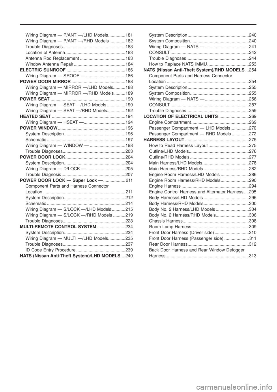
Wiring Diagram Ð P/ANT Ð/LHD Models..............181
Wiring Diagram Ð P/ANT Ð/RHD Models .............182
Trouble Diagnoses...................................................183
Location of Antenna .................................................183
Antenna Rod Replacement .....................................183
Window Antenna Repair ..........................................184
ELECTRIC SUNROOF................................................186
Wiring Diagram Ð SROOF Ð ................................186
POWER DOOR MIRROR............................................188
Wiring Diagram Ð MIRROR Ð/LHD Models..........188
Wiring Diagram Ð MIRROR Ð/RHD Models .........189
POWER SEAT.............................................................190
Wiring Diagram Ð SEAT Ð/LHD Models ...............190
Wiring Diagram Ð SEAT Ð/RHD Models...............192
HEATED SEAT............................................................194
Wiring Diagram Ð HSEAT Ð..................................194
POWER WINDOW.......................................................196
System Description ..................................................196
Schematic ................................................................197
Wiring Diagram Ð WINDOW Ð .............................198
Trouble Diagnoses...................................................203
POWER DOOR LOCK.................................................204
System Description ..................................................204
Wiring Diagram Ð D/LOCK Ð ................................205
Trouble Diagnosis ....................................................207
POWER DOOR LOCK Ð Super Lock Ð.................. 211
Component Parts and Harness Connector
Location ................................................................... 211
System Description ..................................................212
Schematic ................................................................214
Wiring Diagram Ð S/LOCK Ð/LHD Models ...........215
Wiring Diagram Ð S/LOCK Ð/RHD Models ..........219
Trouble Diagnoses...................................................223
MULTI-REMOTE CONTROL SYSTEM.......................234
System Description ..................................................234
Wiring Diagram Ð MULTI Ð/LHD Models..............235
Trouble Diagnoses...................................................237
ID Code Entry Procedure ........................................239
NATS (Nissan Anti-Theft System)/LHD MODELS....240System Description ..................................................240
System Composition ................................................240
Wiring Diagram Ð NATS Ð ....................................241
CONSULT ................................................................242
Trouble Diagnoses...................................................244
How to Replace NATS IMMU ..................................253
NATS (Nissan Anti-Theft System)/RHD MODELS...254
Component Parts and Harness Connector
Location ...................................................................254
System Description ..................................................255
System Composition ................................................255
Wiring Diagram Ð NATS Ð ....................................256
CONSULT ................................................................257
Trouble Diagnoses...................................................259
LOCATION OF ELECTRICAL UNITS.........................269
Engine Compartment ...............................................269
Passenger Compartment Ð LHD Models ...............270
Passenger Compartment Ð RHD Models ..............272
HARNESS LAYOUT....................................................275
How to Read Harness Layout .................................275
Outline/LHD Models.................................................276
Outline/RHD Models ................................................277
Main Harness/LHD Models......................................278
Main Harness/RHD Models .....................................282
Engine Room Harness/LHD Models .......................286
Engine Room Harness/RHD Models .......................290
Engine Harness .......................................................294
Engine Control Harness and Alternator Harness ....295
Body Harness/LHD Models .....................................296
Body Harness/RHD Models.....................................300
Body No. 2 Harness/LHD Models ...........................304
Body No. 2 Harness/RHD Models...........................306
Chassis Harness......................................................308
Room Lamp Harness...............................................309
Front Door Harness (Driver side) ............................310
Front Door Harness (Passenger side) .................... 311
Rear Door Harness..................................................312
Back Door Harness and Rear Window Defogger
Harness....................................................................313
Page 386 of 1226
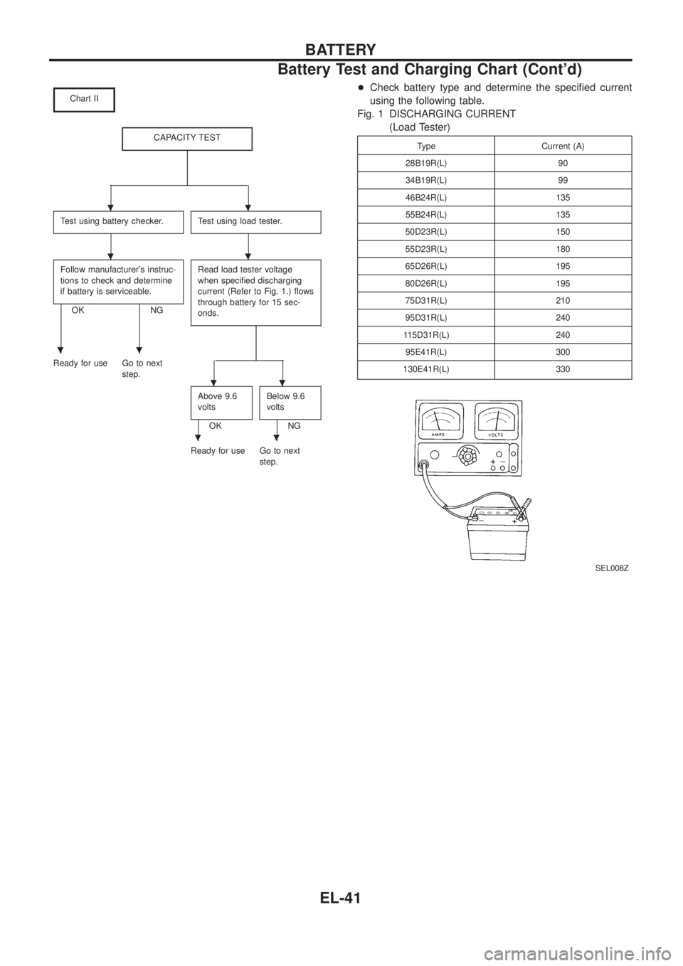
Chart II
CAPACITY TEST
Test using battery checker.Test using load tester.
Follow manufacturer's instruc-
tions to check and determine
if battery is serviceable.
OK NGRead load tester voltage
when speci®ed discharging
current (Refer to Fig. 1.) ¯ows
through battery for 15 sec-
onds.
Ready for use Go to next
step.
Above 9.6
volts
OKBelow 9.6
voltsNG
Ready for use Go to next
step.
+Check battery type and determine the speci®ed current
using the following table.
Fig. 1 DISCHARGING CURRENT
(Load Tester)
Type Current (A)
28B19R(L) 90
34B19R(L) 99
46B24R(L) 135
55B24R(L) 135
50D23R(L) 150
55D23R(L) 180
65D26R(L) 195
80D26R(L) 195
75D31R(L) 210
95D31R(L) 240
115D31R(L) 240
95E41R(L) 300
130E41R(L) 330
SEL008Z
..
..
..
..
..
BATTERY
Battery Test and Charging Chart (Cont'd)
EL-41
Page 401 of 1226
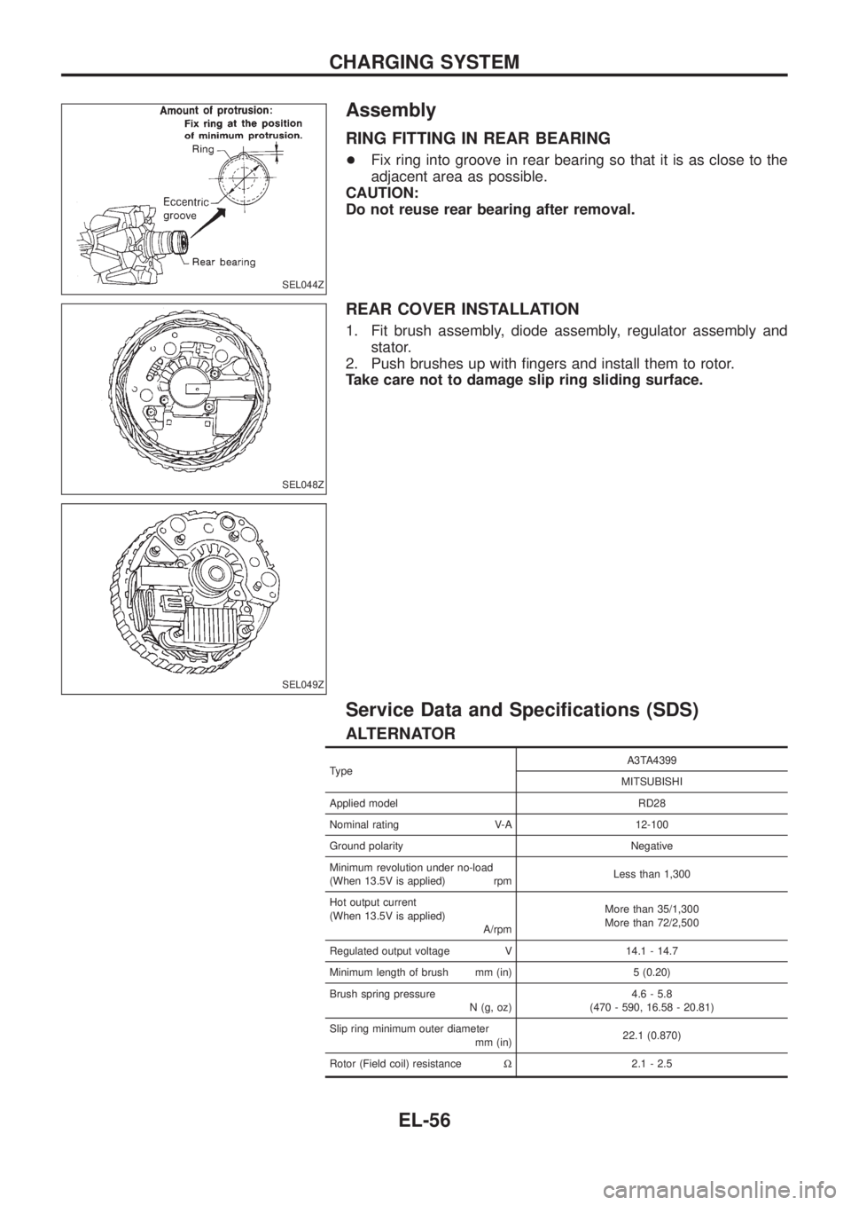
Assembly
RING FITTING IN REAR BEARING
+Fix ring into groove in rear bearing so that it is as close to the
adjacent area as possible.
CAUTION:
Do not reuse rear bearing after removal.
REAR COVER INSTALLATION
1. Fit brush assembly, diode assembly, regulator assembly and
stator.
2. Push brushes up with ®ngers and install them to rotor.
Take care not to damage slip ring sliding surface.
Service Data and Speci®cations (SDS)
ALTERNATOR
TypeA3TA4399
MITSUBISHI
Applied model RD28
Nominal rating V-A 12-100
Ground polarity Negative
Minimum revolution under no-load
(When 13.5V is applied) rpmLess than 1,300
Hot output current
(When 13.5V is applied)
A/rpmMore than 35/1,300
More than 72/2,500
Regulated output voltage V 14.1 - 14.7
Minimum length of brush mm (in) 5 (0.20)
Brush spring pressure
N (g, oz)4.6 - 5.8
(470 - 590, 16.58 - 20.81)
Slip ring minimum outer diameter
mm (in)22.1 (0.870)
Rotor (Field coil) resistanceW2.1 - 2.5
SEL044Z
SEL048Z
SEL049Z
CHARGING SYSTEM
EL-56
Page 519 of 1226
NATS Audio Link/LHD
DESCRIPTION
The link with the NATS IMMU implies that the radio can basically only be operated if connected to the match-
ing NATS IMMU to which the radio was initially ®tted on the production line.
Since radio operation is impossible after the link with the NATS is disrupted theft of the radio unit is basically
useless since special equipment is required to reset the radio.
Initialisation process for radios that are linked to the NATS IMMU
New radios will be delivered to the factories in the ``NEW'' state, i.e. ready to be linked with the vehicle's NATS.
When the radio in ``NEW'' state is ®rst switched on at the factory, it will start up communication with the vehi-
cle's immobiliser control unit (IMMU) and send a code (the ``Radio Code'') to the IMMU. The IMMU will then
store this code, which is unique to each radio, in its (permanent) memory.
Upon receipt of the code by the IMMU, the NATS will con®rm correct receipt of the radio code to the radio.
Hereafter, the radio will operate as normal.
During the initialisation process, ``NEW'' is displayed on the radio display. Normally though, communication
between Radio and IMMU takes such a short time (300 ms) that the radio seems to switch on directly with-
out showing ``NEW'' on its display.
Normal operation
Each time the radio is switched on afterwards, the radio code will be veri®ed between the radio unit and the
NATS before the radio becomes operational. During the code veri®cation process, ``WAIT'' is shown on the
radio display. Again, the communication takes such a short time (300 ms) that the radio seems to switch on
directly without showing ``WAIT'' on its display.
When the radio is locked
In case of a radio being linked with the vehicle's NATS (immobiliser system), disconnection of the link between
the radio and the IMMU will cause the radio to switch into the lock (``SECURE'') mode in which the radio unit
is fully inoperative. Hence, repair of the radio is basically impossible, unless the radio is reset to the ``NEW''
state for which special decoding equipment is required.
Both Blaupunkt and Clarion have provided their authorized service representatives with so called ``decoder
boxes'' which can bring the radio unit back to the ``NEW'' state, enabling the radio to be switched on after which
repair can be carried out. Subsequently, when the repaired radio is delivered to the ®nal user again, it will be
in the ``NEW'' state as to enable re-linking the radio to the vehicle's immobiliser system. As a result of the
above, repair of the radio can only be done by an authorized Blaupunkt or Clarion representative.
Note:
Radio manufacturer of Nissan Y61 models for Europe is ``Clarion''.
SERVICE PROCEDURE
Item Service procedure Description
Battery disconnection No additional action required. Ð
Radio needs repair Repair needs to be done by authorized represen-
tative of radio manufacturer since radio cannot
be operated unless it is reset to NEW state,
using special decoding equipment.Ð
Replacement of radio by new
partNo additional action required. Radio is delivered in NEW state.
Transferring radio to another
vehicle/replacement of radio
by an ``old'' partRadio needs to be reset to NEW state by autho-
rized representative of radio manufacturer.Ð
Replacement of IMMU by
new partNo additional action required. The new IMMU will be recognized by the radio
since a `blank' code is stored in the memory of
the IMMU. In case the radio recognizes this
`blank' code, it will request for input of the correct
CATS code after which the radio will switch back
to the initialisation process.
AUDIO
EL-174
Page 645 of 1226
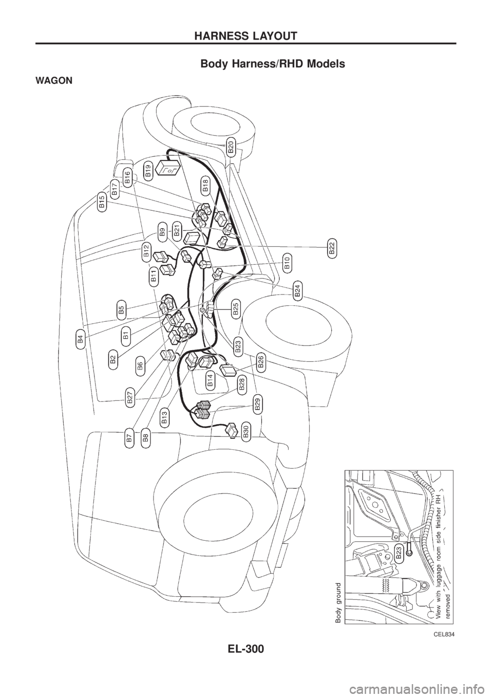
Body Harness/RHD Models
WAGON
CEL834
HARNESS LAYOUT
EL-300
Page 671 of 1226
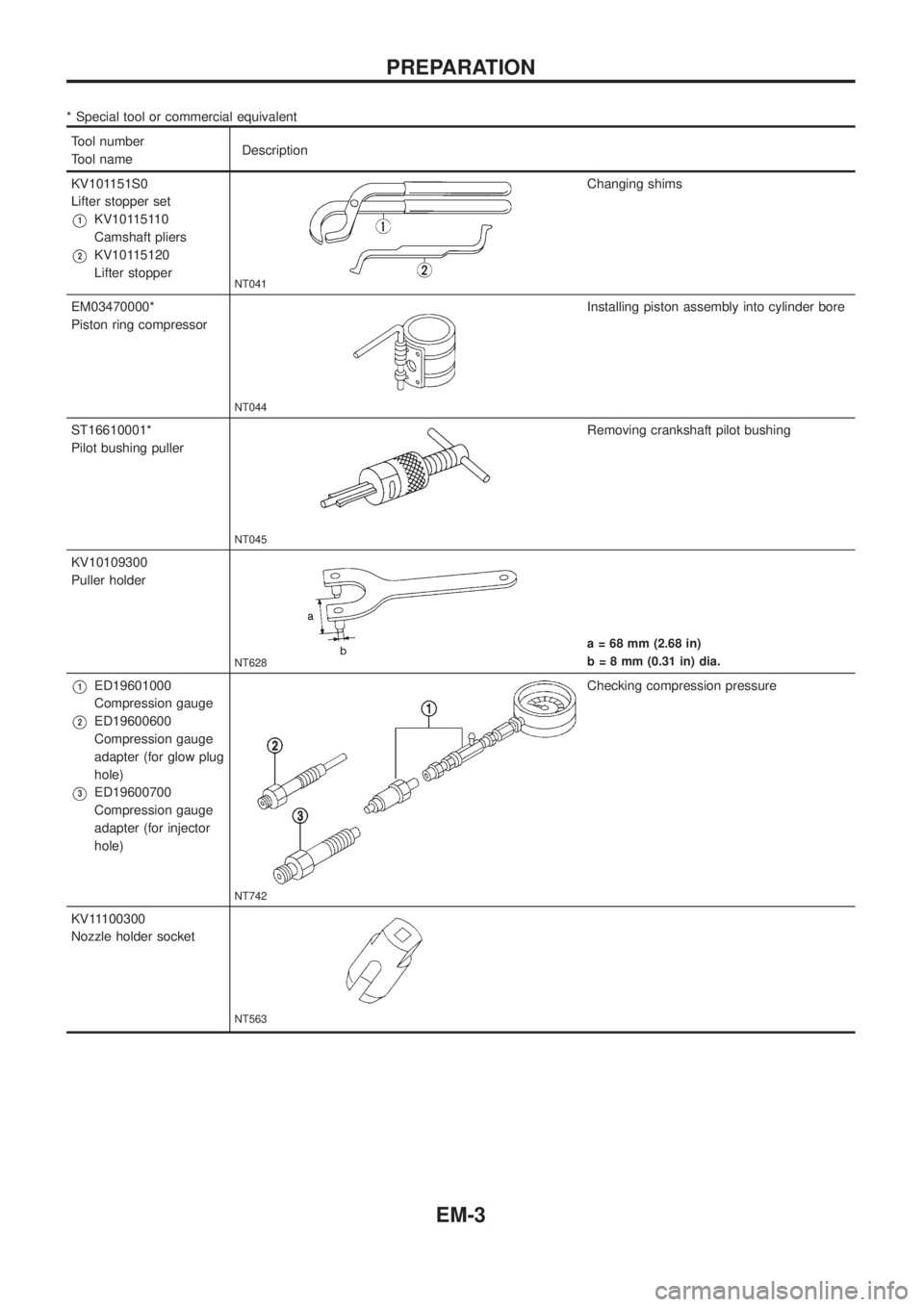
* Special tool or commercial equivalent
Tool number
Tool nameDescription
KV101151S0
Lifter stopper set
V1KV10115110
Camshaft pliers
V2KV10115120
Lifter stopper
NT041
Changing shims
EM03470000*
Piston ring compressor
NT044
Installing piston assembly into cylinder bore
ST16610001*
Pilot bushing puller
NT045
Removing crankshaft pilot bushing
KV10109300
Puller holder
NT628
a = 68 mm (2.68 in)
b = 8 mm (0.31 in) dia.
V1ED19601000
Compression gauge
V2ED19600600
Compression gauge
adapter (for glow plug
hole)
V3ED19600700
Compression gauge
adapter (for injector
hole)
NT742
Checking compression pressure
KV11100300
Nozzle holder socket
NT563
PREPARATION
EM-3