rear suspension NISSAN PATROL 2006 Service Manual
[x] Cancel search | Manufacturer: NISSAN, Model Year: 2006, Model line: PATROL, Model: NISSAN PATROL 2006Pages: 1226, PDF Size: 37.18 MB
Page 1 of 1226
Edition: February 1998
Release: February 1998 (01)
Publication No.: SM8E-0Y61E0E
Reference No.: 7711346063GENERAL INFORMATIONGI
MAINTENANCEMA
ENGINE MECHANICALEM
ENGINE LUBRICATION &
COOLING SYSTEMSLC
ENGINE CONTROL SYSTEMEC
ACCELERATOR CONTROL,
FUEL & EXHAUST SYSTEMFE
CLUTCHCL
MANUAL TRANSMISSIONMT
AUTOMATIC TRANSMISSIONAT
TRANSFERTF
PROPELLER SHAFT &
DIFFERENTIAL CARRIERPD
FRONT AXLE & FRONT SUSPENSIONFA
REAR AXLE & REAR SUSPENSIONRA
BRAKE SYSTEMBR
STEERING SYSTEMST
RESTRAINT SYSTEMRS
BODY & TRIMBT
HEATER & AIR CONDITIONERHA
ELECTRICAL SYSTEMEL
ALPHABETICAL INDEXIDX
PATROL GR
MODEL Y61 SERIES
NISSAN EUROPE S.A.S.
1998 NISSAN EUROPE S.A.S.
Produced in The Netherlands
Not to be reproduced in whole or in part
without the prior written permission of
Nissan Europe S.A.S., Paris, France.
QUICK REFERENCE INDEX
Page 11 of 1226
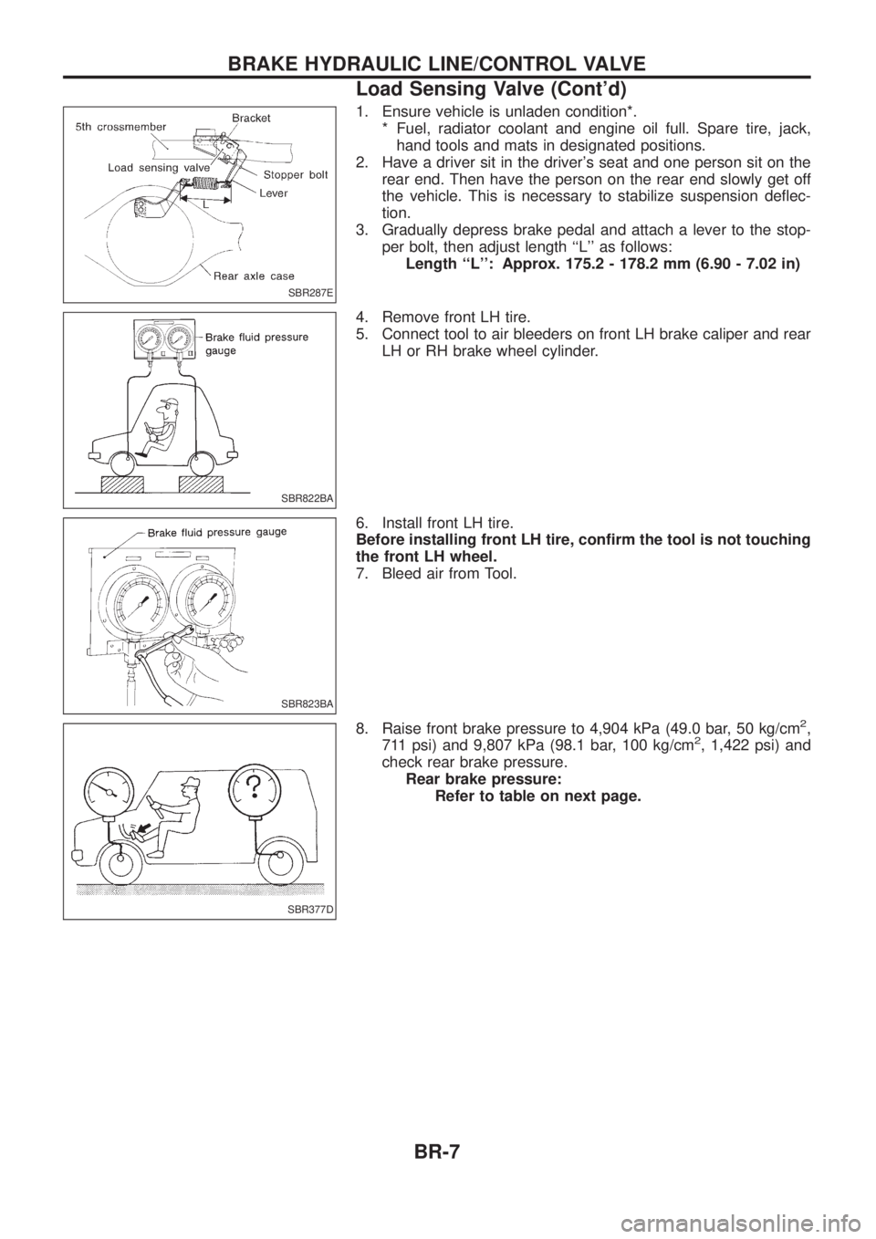
1. Ensure vehicle is unladen condition*.* Fuel, radiator coolant and engine oil full. Spare tire, jack,hand tools and mats in designated positions.
2. Have a driver sit in the driver's seat and one person sit on the rear end. Then have the person on the rear end slowly get off
the vehicle. This is necessary to stabilize suspension de¯ec-
tion.
3. Gradually depress brake pedal and attach a lever to the stop- per bolt, then adjust length ``L'' as follows:Length ``L'': Approx. 175.2 - 178.2 mm (6.90 - 7.02 in)
4. Remove front LH tire.
5. Connect tool to air bleeders on front LH brake caliper and rear LH or RH brake wheel cylinder.
6. Install front LH tire.
Before installing front LH tire, con®rm the tool is not touching
the front LH wheel.
7. Bleed air from Tool.
8. Raise front brake pressure to 4,904 kPa (49.0 bar, 50 kg/cm
2,
711 psi) and 9,807 kPa (98.1 bar, 100 kg/cm2, 1,422 psi) and
check rear brake pressure. Rear brake pressure: Refer to table on next page.
SBR287E
SBR822BA
SBR823BA
SBR377D
BRAKE HYDRAULIC LINE/CONTROL VALVE
Load Sensing Valve (Cont'd)
BR-7
Page 345 of 1226
BULB SPECIFICATIONS............................................314
Headlamp.................................................................314
Exterior Lamp ..........................................................314
Interior Lamp............................................................314
WIRING DIAGRAM CODES (CELL CODES) .............315
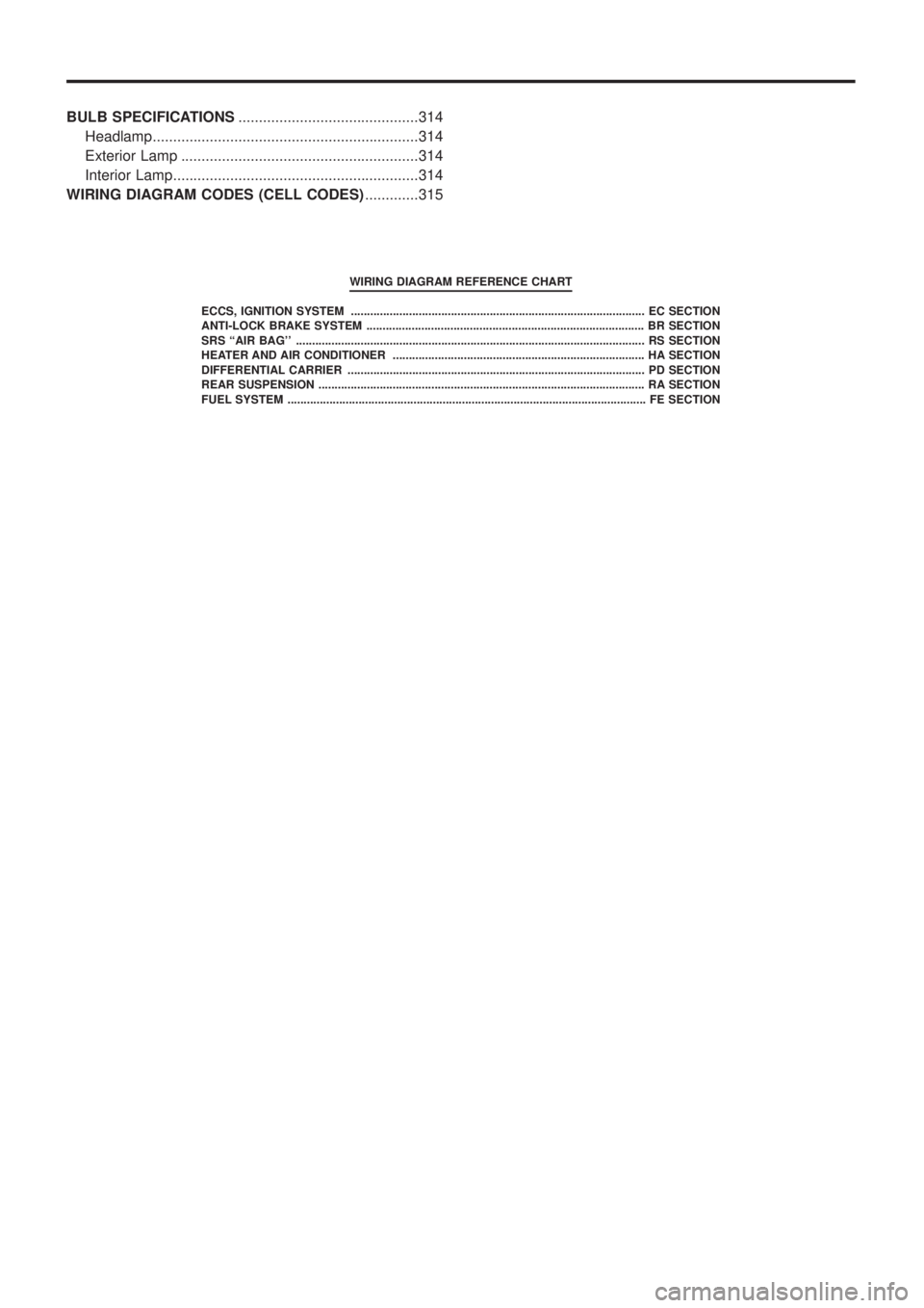
WIRING DIAGRAM REFERENCE CHART
ECCS, IGNITION SYSTEM ........................................................................\
................... EC SECTION
ANTI-LOCK BRAKE SYSTEM ........................................................................\
.............. BR SECTION
SRS ``AIR BAG'' ........................................................................\
.................................... RS SECT ION
HEATER AND AIR CONDITIONER ........................................................................\
...... HA SECTION
DIFFERENTIAL CARRIER ........................................................................\
.................... PD SECTION
REAR SUSPENSION ........................................................................\
............................. RA SECTION
FUEL SYSTEM ........................................................................\
....................................... FE SECT ION
Page 736 of 1226

NVH Troubleshooting Chart
Use the chart below to help you ®nd the cause of the symptom. If necessary, repair or replace these parts.
Reference pageFA-4
FA-25
Ð
Ð
Ð
FA-24
FA-8
FA-25
FA-5
FA-8
Ð
Ð
Ð
Ð
Ð
Ð
Ð
FA-23
Ð
NVH in PD section
NVH in PD section
Refer to FRONT AXLE AND FRONT SUSPENSION in this chart.
NVH in RA section
Refer to TIRES in this chart.
Refer to ROAD WHEEL in this chart.
Refer to AXLE SHAFT in this chart.
NVH in BR section
NVH in ST section
Possible cause and SUSPECTED PARTS
Improper installation, looseness
Shock absorber deformation, damage or de¯ection
Bushing or mounting deterioration
Parts interference
Spring fatigue
Suspension looseness
Incorrect wheel alignment
Stabilizer bar fatigue
Wheel bearing damage
Out-of-round
Imbalance
Incorrect air pressure
Uneven tire wear
Deformation or damage
Non-uniformity
Incorrect tire size
Excessive joint angle
Joint sliding resistance
Imbalance
PROPELLER SHAFT
DIFFERENTIAL
FRONT AXLE AND FRONT SUSPENSION
REAR AXLE AND REAR SUSPENSION
TIRES
ROAD WHEEL
AXLE SHAFT
BRAKES
STEERING
SymptomFRONT
AXLE AND
FRONT
SUSPEN-
SIONNoiseXXXXXX XX XXXXXX
ShakeXXXX X X XXXXXX
VibrationXXXXX X XX X X
ShimmyXXXX X XXX XX
Judder X X XXXX XX
Poor quality ride
or handlingXXXXX XXX XXX
TIRESNoise XXXXXXX XXXX XXXX
Shake XXXXXX X X XX XXXX
Vibration X X X X X X X
Shimmy XXXXXXXX XX X XX
Judder XXXXXX X XX X XX
Poor quality ride
or handlingX XXXXX X XX X
ROAD
WHEELNoise X X X XXXXXX XXX
Shake X X X X X X X X X X X
Shimmy, judder X X X X X X X X X
Poor quality ride
or handlingX XX X XXX
AXLE
SHAFTNoise, vibration X XXXXXXX XX
ShakeX XX XXXX XX
X: Applicable
NOISE, VIBRATION AND HARSHNESS (NVH) TROUBLESHOOTING
FA-3
Page 953 of 1226
ROOM/L - Wiring diagram ..............................EL-95
Radiator ..........................................................LC-14
Radio - See Audio.........................................EL-168
Rear axle (disc brake type) ..............................RA-6
Rear bumper .....................................................BT-6
Rear case (Transfer) .......................................TF-10
Rear combination lamp removal and
installation ...................................................BT-26
Rear cover packing replacement diff..............PD-11
Rear disc brake ..............................................BR-24
Rear door ........................................................BT-10
Rear fog lamp .................................................EL-80
Rear heater - Wiring diagram ........................HA-14
Rear seat belt ...................................................RS-5
Rear seat ........................................................BT-35
Rear side window ...........................................BT-44
Rear suspension ............................................RA-12
Rear washer..................................................EL-145
Rear window defogger ..................................EL-158
Rear window ...................................................BT-42
Rear wiper.....................................................EL-145
Refrigerant connection precaution ...................HA-2
Refrigerant discharging evacuating
charging ....................................................HA-113
Refrigerant general precaution.........................HA-2
Refrigerant lines ...........................................HA-117
Refrigeration cycle ..........................................HA-11
Release bearing (clutch) .................................CL-11
Removal and installation (Transfer) ..................TF-8
Reverse idler shaft (M/T) ...............................MT-10
Reverse lamp switch (M/T) - See
Back-up lamp switch (M/T)...........................MT-4
Reverse main gear (M/T) ...............................MT-10
Ring gear diff. inspection ...............................PD-19
Road wheel size ..............................................GI-38
Roof trim .........................................................BT-20
Room lamp - See Interior lamp ......................EL-93
Rotor disc (front) .............................................FA-14
S
S/LOCK - Wiring diagram .............................EL-215
S/SIG - Wiring diagram ................................EC-162
SAE J1930 terminology list .............................GI-43
SEAT - Wiring diagram .................................EL-190
SMJ (super multiple junction) .......................EL-317
SROOF - Wiring diagram .............................EL-186
SRS - See Supplemental Restraint
System ..........................................................RS-8
SRS Trouble diagnoses .................................RS-22
STAB - Wiring diagram ..................................RA-18
START - Wiring diagram .................................EL-45
Screw jack .......................................................GI-39
Seal - See Exterior .........................................BT-26
Seat belt inspection .......................................MA-27
Seat belt pre-tensioner disposal ....................RS-17
Seat belt pre-tensioner ...................................RS-12
Seat belt, front ..................................................RS-2
Seat belt, rear...................................................RS-5Seat, front .......................................................BT-32
Seat, rear ........................................................BT-35
Seat, second (2nd) .........................................BT-35
Seat, third (3rd) ...............................................BT-37
Second (2nd) seat ..........................................BT-35
Self-diagnostic results ....................................EC-31
Shift control (Transfer) ....................................TF-12
Shift control components (M/T) ......................MT-12
Shift fork (M/T) ...............................................MT-12
Shift lever .......................................................MT-12
Shock absorber (front) ....................................FA-25
Shock absorber (rear) ....................................RA-14
Side bearing preload (front ®nal drive
4WD)...........................................................PD-27
Side bearing preload diff. ...............................PD-27
Side trim ..........................................................BT-14
Side window - See Rear side window ............BT-44
Speedometer.................................................EL-102
Spiral cable.....................................................RS-13
Stabilizer bar (front) ........................................FA-25
Stabilizer bar (rear) ........................................RA-15
Stabilizer release device - Wiring
diagram .......................................................RA-18
Stabilizer release device ................................RA-16
Standardized relay ............................................EL-3
Start signal ...................................................EC-162
Starter .............................................................EL-51
Starting system ...............................................EL-45
Steering gear and linkage inspection ............MA-26
Steering linkage ..............................................ST-19
Steering switch................................................EL-59
Steering wheel and column ..............................ST-8
Steering wheel play ..........................................ST-4
Steering wheel turning force .............................ST-6
Striking rod (M/T) ...........................................MT-12
Sub-gear (M/T) ...............................................MT-10
Sunload sensor ............................................HA-107
Sunroof, electric ............................................EL-186
Sunroof............................................................BT-39
Super lock .....................................................EL-211
Supplemental Restraint System .......................RS-8
Supplemental restraint system - Wiring
diagram .......................................................RS-27
Symbols and abbreviations ...............................GI-7
Synchronizer (M/T) .........................................MT-10
T
TCV - Wiring diagram ..................................EC-100
Tachometer ...................................................EL-102
Thermometer .................................................EL-116
Thermostat ......................................................LC-12
Third (3rd) seat ...............................................BT-37
Three way catalyst precautions.........................GI-4
Throttle control solenoid valve .....................EC-155
Throttle control solenoid valve .....................EC-161
Throwout bearing - See Clutch release
bearing ........................................................CL-11
Thrust washer selection diff. ..........................PD-27
ALPHABETICAL INDEX
IDX-6
Page 979 of 1226
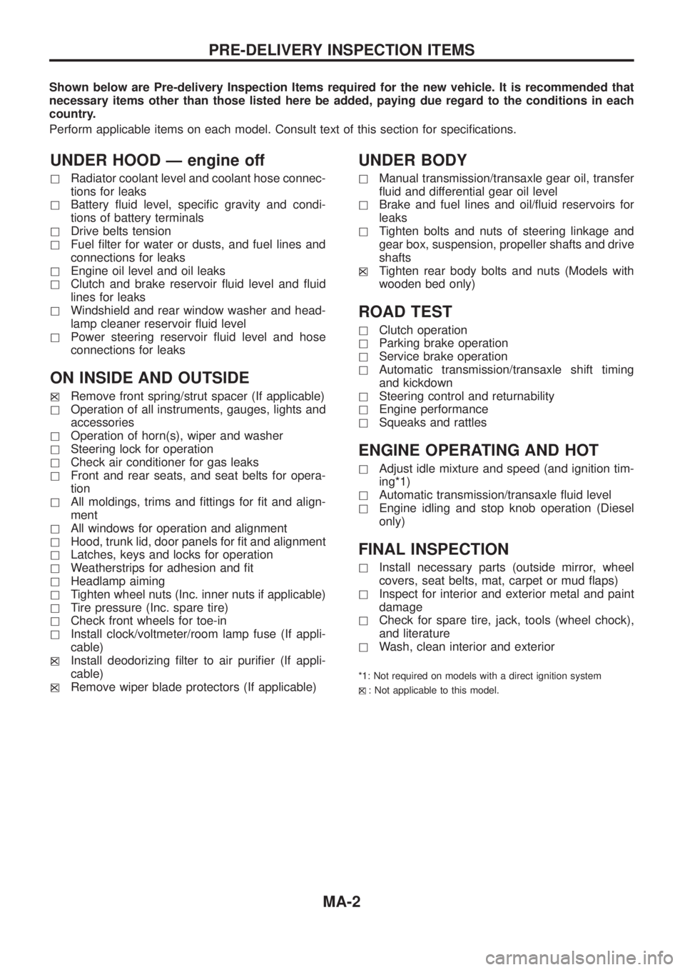
Shown below are Pre-delivery Inspection Items required for the new vehicle. It is recommended that
necessary items other than those listed here be added, paying due regard to the conditions in each
country.
Perform applicable items on each model. Consult text of this section for speci®cations.
UNDER HOOD Ð engine off
hRadiator coolant level and coolant hose connec-
tions for leaks
hBattery ¯uid level, speci®c gravity and condi-
tions of battery terminals
hDrive belts tension
hFuel ®lter for water or dusts, and fuel lines and
connections for leaks
hEngine oil level and oil leaks
hClutch and brake reservoir ¯uid level and ¯uid
lines for leaks
hWindshield and rear window washer and head-
lamp cleaner reservoir ¯uid level
hPower steering reservoir ¯uid level and hose
connections for leaks
ON INSIDE AND OUTSIDE
hXRemove front spring/strut spacer (If applicable)
hOperation of all instruments, gauges, lights and
accessories
hOperation of horn(s), wiper and washer
hSteering lock for operation
hCheck air conditioner for gas leaks
hFront and rear seats, and seat belts for opera-
tion
hAll moldings, trims and ®ttings for ®t and align-
ment
hAll windows for operation and alignment
hHood, trunk lid, door panels for ®t and alignment
hLatches, keys and locks for operation
hWeatherstrips for adhesion and ®t
hHeadlamp aiming
hTighten wheel nuts (Inc. inner nuts if applicable)
hTire pressure (Inc. spare tire)
hCheck front wheels for toe-in
hInstall clock/voltmeter/room lamp fuse (If appli-
cable)
h
XInstall deodorizing ®lter to air puri®er (If appli-
cable)
h
XRemove wiper blade protectors (If applicable)
UNDER BODY
hManual transmission/transaxle gear oil, transfer
¯uid and differential gear oil level
hBrake and fuel lines and oil/¯uid reservoirs for
leaks
hTighten bolts and nuts of steering linkage and
gear box, suspension, propeller shafts and drive
shafts
h
XTighten rear body bolts and nuts (Models with
wooden bed only)
ROAD TEST
hClutch operation
hParking brake operation
hService brake operation
hAutomatic transmission/transaxle shift timing
and kickdown
hSteering control and returnability
hEngine performance
hSqueaks and rattles
ENGINE OPERATING AND HOT
hAdjust idle mixture and speed (and ignition tim-
ing*1)
hAutomatic transmission/transaxle ¯uid level
hEngine idling and stop knob operation (Diesel
only)
FINAL INSPECTION
hInstall necessary parts (outside mirror, wheel
covers, seat belts, mat, carpet or mud ¯aps)
hInspect for interior and exterior metal and paint
damage
hCheck for spare tire, jack, tools (wheel chock),
and literature
hWash, clean interior and exterior
*1: Not required on models with a direct ignition system
h
X: Not applicable to this model.
PRE-DELIVERY INSPECTION ITEMS
MA-2
Page 983 of 1226

Chassis and Body Services
Annual driving distance below 30,000 km (18,000 miles)
Abbreviations: R = Replace, I = Inspect, and correct or replace as necessary, L = Lubricate,T=Tighten.
[ ]: At the speci®ed mileage only
MAINTENANCE OPERATIONMAINTENANCE INTERVAL
Reference
page Perform either at number of kilometers (miles) or months,
whichever comes ®rst.km x 1,000 10 20 30 40 50 60 70 80 90
(Miles x 1,000) (6) (12) (18) (24) (30) (36) (42) (48) (54)
Months 6 12 18 24 30 36 42 48 54
CHASSIS AND BODY Underhood and under vehicle
Brake & clutch ¯uid (For level & leaks).I I I I MA-23, 20
Brake ¯uid.R R MA-24
Brake booster vacuum hoses, connections & check valve I I MA-24
Power steering ¯uid & lines (For level & leaks) I I I I MA-26
Brake & clutch systemsI I I I MA-24, 20
Manual transmission oil (For leaks) I I I I MA-20
Manual transmission oil[R] MA-20
Transfer ¯uidI I R I MA-21
Limited slip differential (LSD) gear oil (For level & leaks).*1 I I R I MA-22
Steering gear & linkage, axle & suspension parts, propeller shaft & exhaust system.I I I I MA-26, 20 *2
Greasing points of propeller shaftLLLLMA-21
Drive shafts & steering damper.IIII *3
Body mounting bolts & nutsTTTT *4
Outside and Inside
Wheel alignment (If necessary, rotate & balance wheels) I I I I MA-25, *5
Brake pads, discs & other brake components.I I I I MA-24
Front wheel bearing grease I R I R MA-22
Axle joint in knuckle ¯angeL L MA-23
Free running hub greaseI I I I MA-23
Headlamp aimingIIII *6
Foot brake, parking brake & clutch (For free play, stroke & operation) I I I I *7
Ventilation air ®lterRRR*8
Body corrosionAnnually MA-28
Air bag systemSee NOTE (1) *9
NOTE: (1) Inspect after 10 years, then every 2 years.
(2) Maintenance items with ``.'' should be performed more frequently according to ``Maintenance Under Severe Driv-
ing Conditions''.
*1: Including differential gear with differential lock
*2: ``Front Axle and Front Suspension Parts'' in FA section, ``Rear Axle and Rear Suspension Parts'' in RA section
*3: ``FRONT AXLE Ð Drive Shaft'' in FA section
*4: ``CAB BODY'' in BT section
*5: ``Front Wheel Alignment'' in FA section
*6: ``Aiming Adjustment'' in EL section
*7: ``Brake Pedal and Bracket'' in BR section, ``Adjusting Clutch Pedal'' in CL section
*8: ``Ventilation air ®lter'' in HA section
*9: ``Maintenance Items'' in RS section
PERIODIC MAINTENANCE
MA-6
Page 984 of 1226
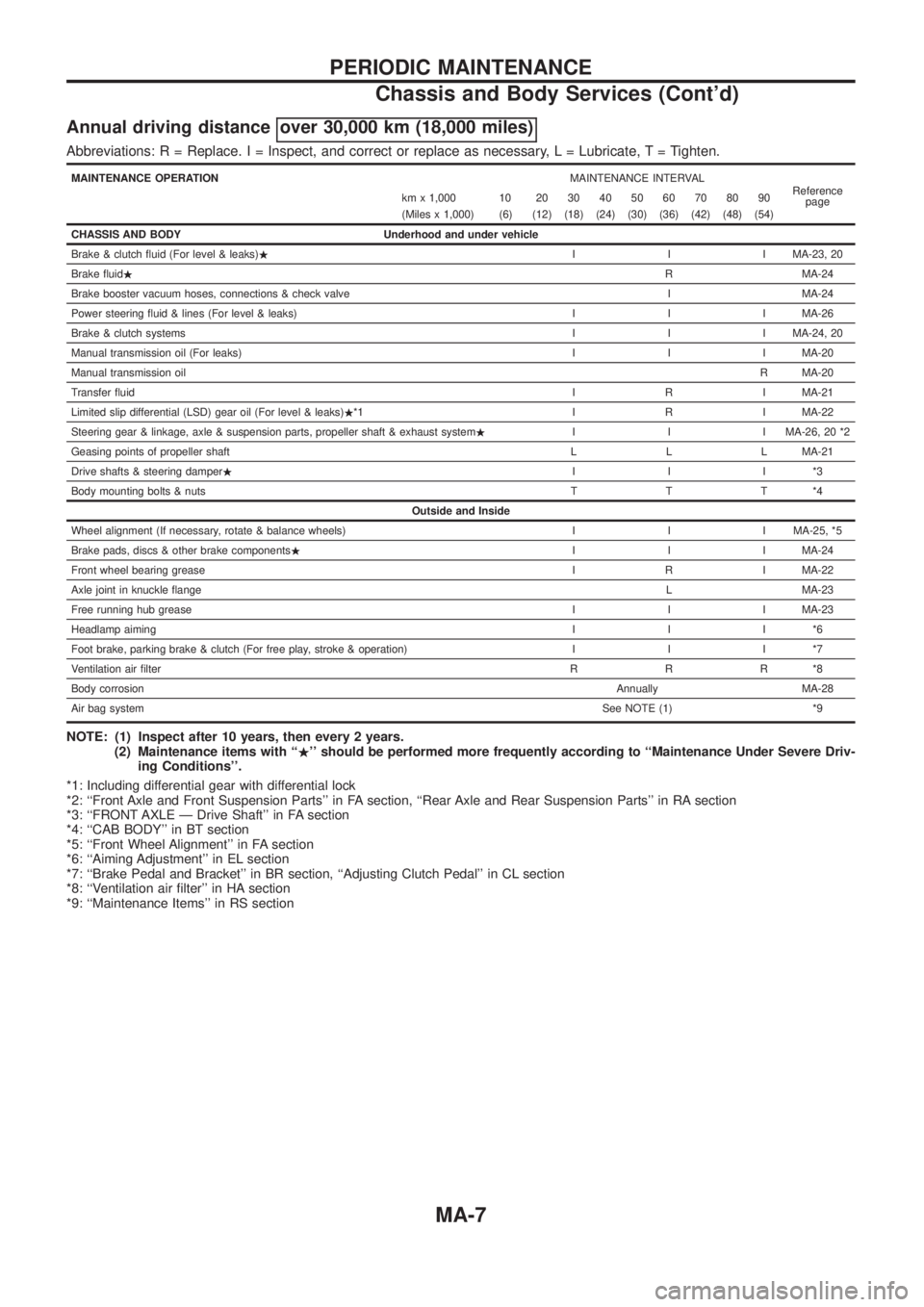
Annual driving distance over 30,000 km (18,000 miles)
Abbreviations: R = Replace. I = Inspect, and correct or replace as necessary, L = Lubricate,T=Tighten.
MAINTENANCE OPERATIONMAINTENANCE INTERVAL
Reference
page km x 1,000 10 20 30 40 50 60 70 80 90
(Miles x 1,000) (6) (12) (18) (24) (30) (36) (42) (48) (54)
CHASSIS AND BODY Underhood and under vehicle
Brake & clutch ¯uid (For level & leaks).I I I MA-23, 20
Brake ¯uid.R MA-24
Brake booster vacuum hoses, connections & check valve I MA-24
Power steering ¯uid & lines (For level & leaks) I I I MA-26
Brake & clutch systemsI I I MA-24, 20
Manual transmission oil (For leaks) I I I MA-20
Manual transmission oilR MA-20
Transfer ¯uidI R I MA-21
Limited slip differential (LSD) gear oil (For level & leaks).*1 I R I MA-22
Steering gear & linkage, axle & suspension parts, propeller shaft & exhaust system.I I I MA-26, 20 *2
Geasing points of propeller shaft L L L MA-21
Drive shafts & steering damper.III*3
Body mounting bolts & nutsTTT*4
Outside and Inside
Wheel alignment (If necessary, rotate & balance wheels) I I I MA-25, *5
Brake pads, discs & other brake components.I I I MA-24
Front wheel bearing greaseI R I MA-22
Axle joint in knuckle ¯angeL MA-23
Free running hub greaseI I I MA-23
Headlamp aimingIII*6
Foot brake, parking brake & clutch (For free play, stroke & operation) I I I *7
Ventilation air ®lterRRR*8
Body corrosionAnnually MA-28
Air bag systemSee NOTE (1) *9
NOTE: (1) Inspect after 10 years, then every 2 years.
(2) Maintenance items with ``.'' should be performed more frequently according to ``Maintenance Under Severe Driv-
ing Conditions''.
*1: Including differential gear with differential lock
*2: ``Front Axle and Front Suspension Parts'' in FA section, ``Rear Axle and Rear Suspension Parts'' in RA section
*3: ``FRONT AXLE Ð Drive Shaft'' in FA section
*4: ``CAB BODY'' in BT section
*5: ``Front Wheel Alignment'' in FA section
*6: ``Aiming Adjustment'' in EL section
*7: ``Brake Pedal and Bracket'' in BR section, ``Adjusting Clutch Pedal'' in CL section
*8: ``Ventilation air ®lter'' in HA section
*9: ``Maintenance Items'' in RS section
PERIODIC MAINTENANCE
Chassis and Body Services (Cont'd)
MA-7
Page 985 of 1226
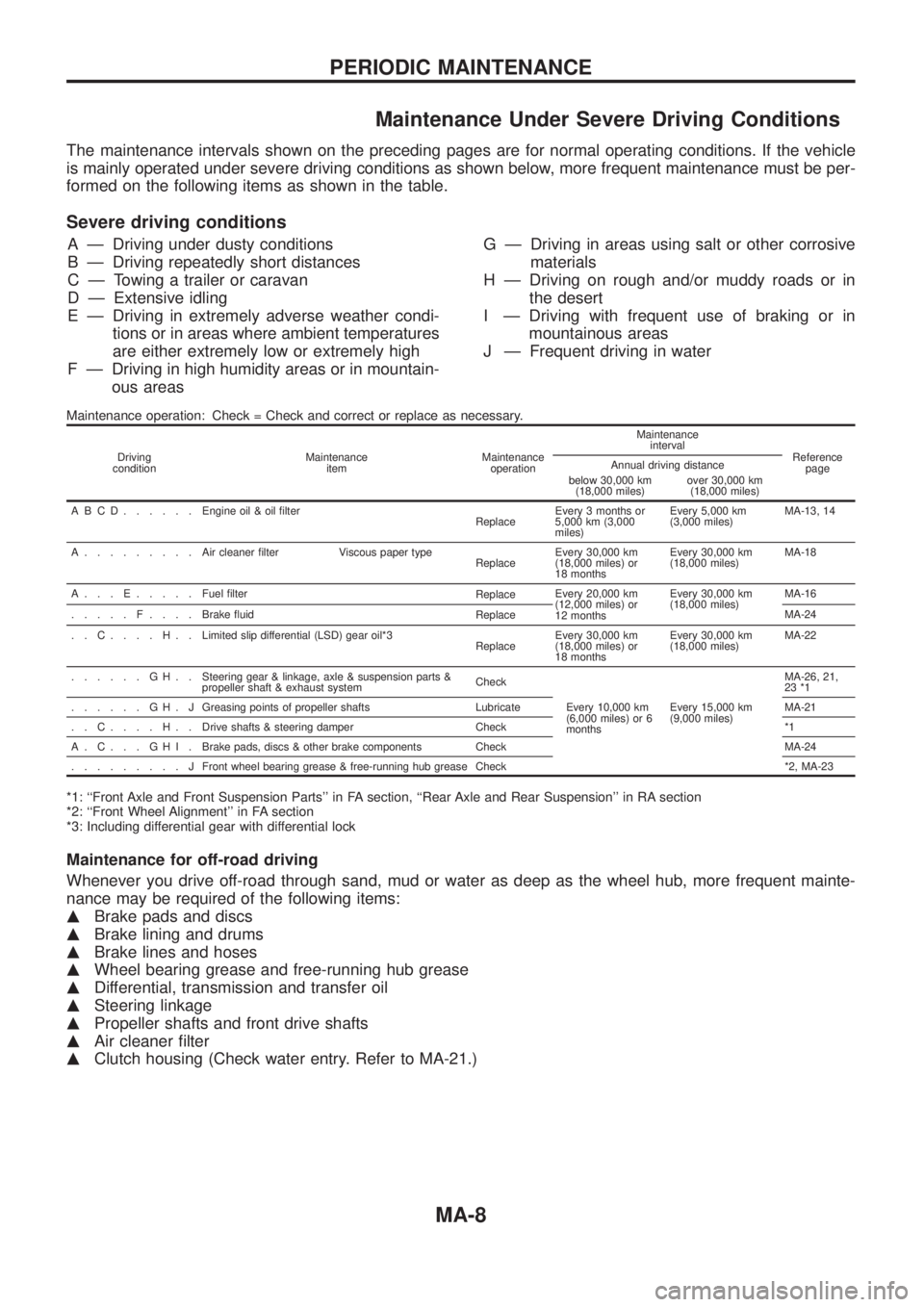
Maintenance Under Severe Driving Conditions
The maintenance intervals shown on the preceding pages are for normal operating conditions. If the vehicle
is mainly operated under severe driving conditions as shown below, more frequent maintenance must be per-
formed on the following items as shown in the table.
Severe driving conditions
A Ð Driving under dusty conditions
B Ð Driving repeatedly short distances
C Ð Towing a trailer or caravan
D Ð Extensive idling
E Ð Driving in extremely adverse weather condi-
tions or in areas where ambient temperatures
are either extremely low or extremely high
F Ð Driving in high humidity areas or in mountain-
ous areasG Ð Driving in areas using salt or other corrosive
materials
H Ð Driving on rough and/or muddy roads or in
the desert
I Ð Driving with frequent use of braking or in
mountainous areas
J Ð Frequent driving in water
Maintenance operation: Check = Check and correct or replace as necessary.
Driving
conditionMaintenance
itemMaintenance
operationMaintenance
interval
Reference
page Annual driving distance
below 30,000 km
(18,000 miles)over 30,000 km
(18,000 miles)
ABCD......Engine oil & oil ®lter
ReplaceEvery 3 months or
5,000 km (3,000
miles)Every 5,000 km
(3,000 miles)MA-13, 14
A.........Aircleaner ®lter Viscous paper type
ReplaceEvery 30,000 km
(18,000 miles) or
18 monthsEvery 30,000 km
(18,000 miles)MA-18
A...E.....Fuel ®lter
ReplaceEvery 20,000 km
(12,000 miles) or
12 monthsEvery 30,000 km
(18,000 miles)MA-16
.....F....Brake ¯uid
ReplaceMA-24
..C....H..Limited slip differential (LSD) gear oil*3
ReplaceEvery 30,000 km
(18,000 miles) or
18 monthsEvery 30,000 km
(18,000 miles)MA-22
......GH..Steering gear & linkage, axle & suspension parts &
propeller shaft & exhaust systemCheck
Every 10,000 km
(6,000 miles) or 6
monthsEvery 15,000 km
(9,000 miles)MA-26, 21,
23 *1
......GH.JGreasing points of propeller shafts Lubricate MA-21
..C....H..Drive shafts & steering damper Check *1
A.C...GHI.Brake pads, discs & other brake components Check MA-24
.........JFront wheel bearing grease & free-running hub grease Check *2, MA-23
*1: ``Front Axle and Front Suspension Parts'' in FA section, ``Rear Axle and Rear Suspension'' in RA section
*2: ``Front Wheel Alignment'' in FA section
*3: Including differential gear with differential lock
Maintenance for off-road driving
Whenever you drive off-road through sand, mud or water as deep as the wheel hub, more frequent mainte-
nance may be required of the following items:
mBrake pads and discs
mBrake lining and drums
mBrake lines and hoses
mWheel bearing grease and free-running hub grease
mDifferential, transmission and transfer oil
mSteering linkage
mPropeller shafts and front drive shafts
mAir cleaner ®lter
mClutch housing (Check water entry. Refer to MA-21.)
PERIODIC MAINTENANCE
MA-8
Page 1096 of 1226
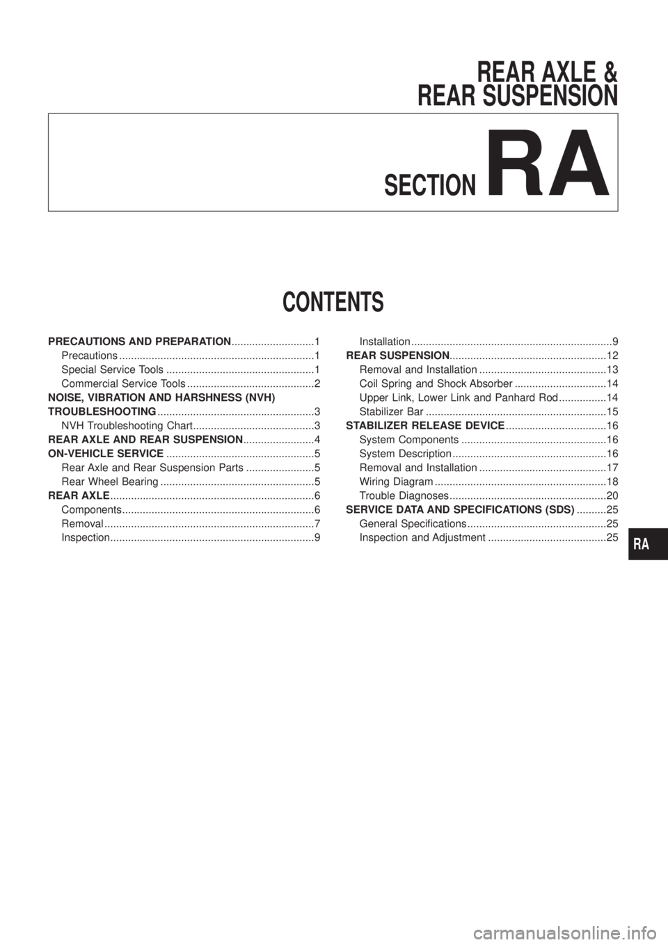
REAR AXLE &
REAR SUSPENSION
SECTION
RA
CONTENTS
PRECAUTIONS AND PREPARATION............................1
Precautions ..................................................................1
Special Service Tools ..................................................1
Commercial Service Tools ...........................................2
NOISE, VIBRATION AND HARSHNESS (NVH)
TROUBLESHOOTING.....................................................3
NVH Troubleshooting Chart.........................................3
REAR AXLE AND REAR SUSPENSION........................4
ON-VEHICLE SERVICE..................................................5
Rear Axle and Rear Suspension Parts .......................5
Rear Wheel Bearing ....................................................5
REAR AXLE.....................................................................6
Components.................................................................6
Removal .......................................................................7
Inspection.....................................................................9Installation ....................................................................9
REAR SUSPENSION.....................................................12
Removal and Installation ...........................................13
Coil Spring and Shock Absorber ...............................14
Upper Link, Lower Link and Panhard Rod ................14
Stabilizer Bar .............................................................15
STABILIZER RELEASE DEVICE..................................16
System Components .................................................16
System Description ....................................................16
Removal and Installation ...........................................17
Wiring Diagram ..........................................................18
Trouble Diagnoses.....................................................20
SERVICE DATA AND SPECIFICATIONS (SDS)..........25
General Speci®cations ...............................................25
Inspection and Adjustment ........................................25
RA