checking oil NISSAN PICK-UP 1998 User Guide
[x] Cancel search | Manufacturer: NISSAN, Model Year: 1998, Model line: PICK-UP, Model: NISSAN PICK-UP 1998Pages: 1659, PDF Size: 53.39 MB
Page 896 of 1659
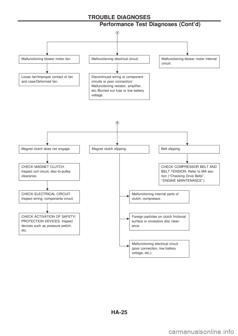
VA
Malfunctioning blower motor fan.Malfunctioning electrical circuit.Malfunctioning blower motor internal
circuit.
Loose fan/Improper contact of fan
and case/Deformed fan.Discontinued wiring or component
circuits or poor connection/
Malfunctioning resistor, amplifier,
etc./Burned out fuse or low battery
voltage.
VB
Magnet clutch does not engage.Magnet clutch slipping.Belt slipping.
CHECK MAGNET CLUTCH.
Inspect coil circuit, disc-to-pulley
clearance.CHECK COMPRESSOR BELT AND
BELT TENSION. Refer to MA sec-
tion (``Checking Drive Belts'',
``ENGINE MAINTENANCE'').
CHECK ELECTRICAL CIRCUIT.
Inspect wiring, components circuit.cMalfunctioning internal parts of
clutch, compressor.
CHECK ACTIVATION OF SAFETY/
PROTECTION DEVICES. Inspect
devices such as pressure switch,
etc.cForeign particles on clutch frictional
surface or excessive disc clear-
ance.
cMalfunctioning electrical circuit
(poor connection, low battery
voltage, etc.).
...
..
...
..
.
.
TROUBLE DIAGNOSES
Performance Test Diagnoses (Cont'd)
HA-25
Page 910 of 1659
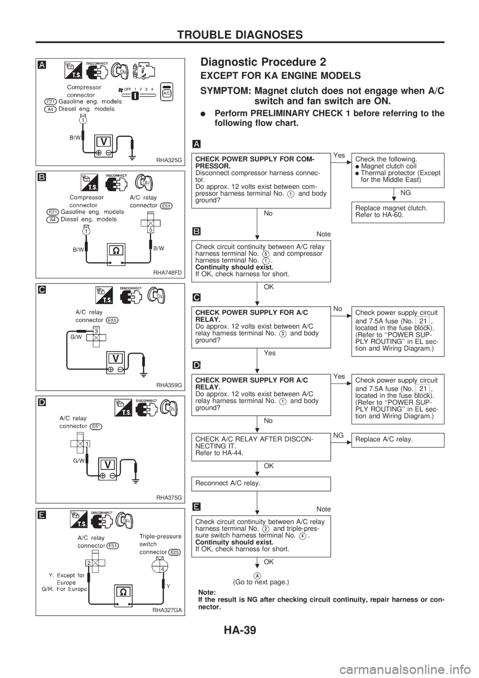
Diagnostic Procedure 2
EXCEPT FOR KA ENGINE MODELS
SYMPTOM: Magnet clutch does not engage when A/C
switch and fan switch are ON.
lPerform PRELIMINARY CHECK 1 before referring to the
following flow chart.
CHECK POWER SUPPLY FOR COM-
PRESSOR.
Disconnect compressor harness connec-
tor.
Do approx. 12 volts exist between com-
pressor harness terminal No.
V1and body
ground?
No
cYes
Check the following.
lMagnet clutch coillThermal protector (Except
for the Middle East)
NG
Replace magnet clutch.
Refer to HA-60.
Note
Check circuit continuity between A/C relay
harness terminal No.
V5and compressor
harness terminal No.
V1.
Continuity should exist.
If OK, check harness for short.
OK
CHECK POWER SUPPLY FOR A/C
RELAY.
Do approx. 12 volts exist between A/C
relay harness terminal No.
V3and body
ground?
Yes
cNo
Check power supply circuit
and 7.5A fuse (No.
21 ,
located in the fuse block).
(Refer to ``POWER SUP-
PLY ROUTING'' in EL sec-
tion and Wiring Diagram.)
CHECK POWER SUPPLY FOR A/C
RELAY.
Do approx. 12 volts exist between A/C
relay harness terminal No.
V1and body
ground?
No
cYes
Check power supply circuit
and 7.5A fuse (No.
21 ,
located in the fuse block).
(Refer to ``POWER SUP-
PLY ROUTING'' in EL sec-
tion and Wiring Diagram.)
CHECK A/C RELAY AFTER DISCON-
NECTING IT.
Refer to HA-44.
OK
cNG
Replace A/C relay.
Reconnect A/C relay.
Note
Check circuit continuity between A/C relay
harness terminal No.
V2and triple-pres-
sure switch harness terminal No.
V4.
Continuity should exist.
If OK, check harness for short.
OK
VA(Go to next page.)
Note:
If the result is NG after checking circuit continuity, repair harness or con-
nector.
RHA325G
RHA748FD
RHA359G
RHA375G
RHA327GA
.
.
.
.
.
.
.
.
TROUBLE DIAGNOSES
HA-39
Page 912 of 1659
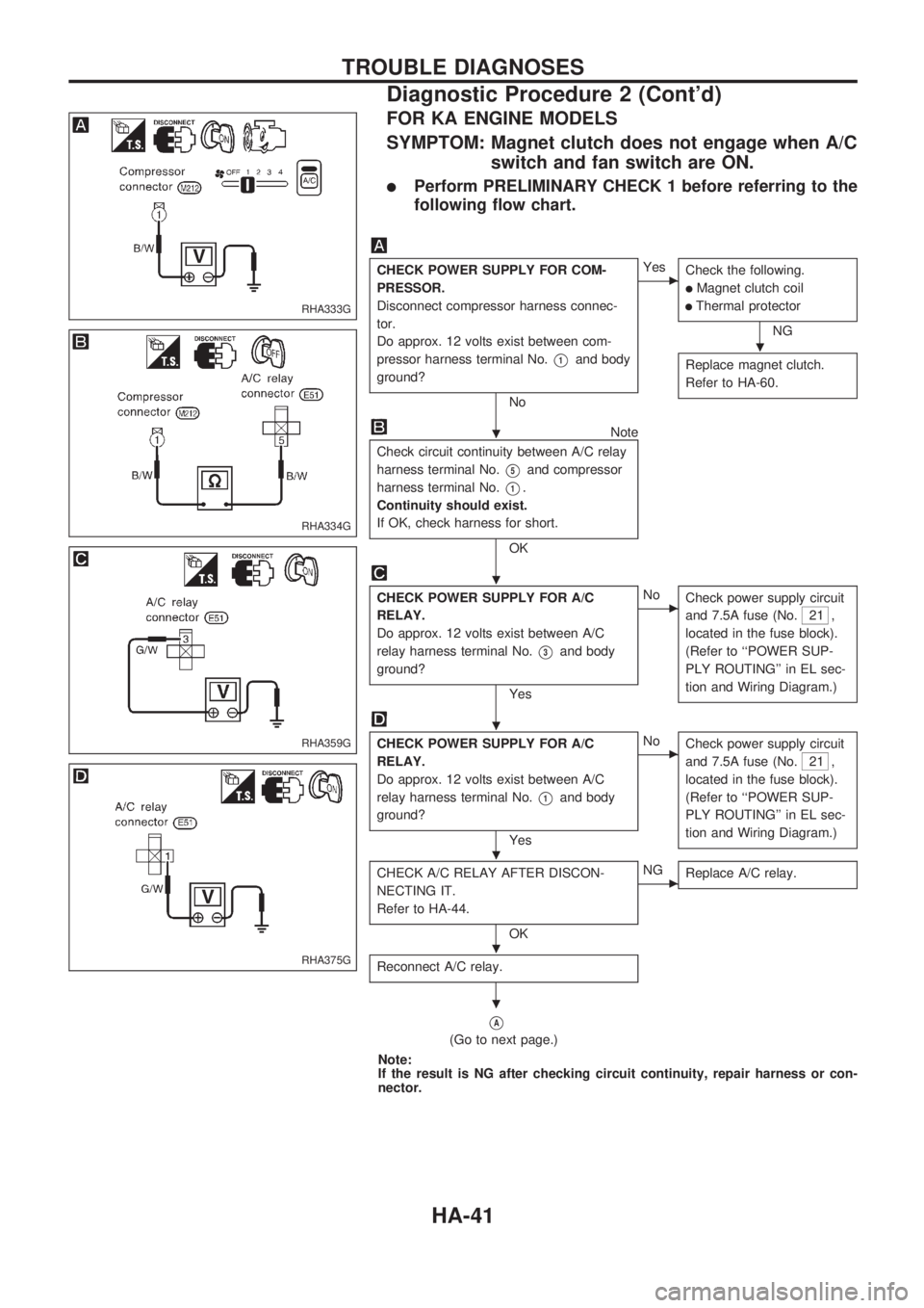
FOR KA ENGINE MODELS
SYMPTOM: Magnet clutch does not engage when A/C
switch and fan switch are ON.
lPerform PRELIMINARY CHECK 1 before referring to the
following flow chart.
CHECK POWER SUPPLY FOR COM-
PRESSOR.
Disconnect compressor harness connec-
tor.
Do approx. 12 volts exist between com-
pressor harness terminal No.
V1and body
ground?
No
cYes
Check the following.
lMagnet clutch coil
lThermal protector
NG
Replace magnet clutch.
Refer to HA-60.
Note
Check circuit continuity between A/C relay
harness terminal No.
V5and compressor
harness terminal No.
V1.
Continuity should exist.
If OK, check harness for short.
OK
CHECK POWER SUPPLY FOR A/C
RELAY.
Do approx. 12 volts exist between A/C
relay harness terminal No.
V3and body
ground?
Yes
cNo
Check power supply circuit
and 7.5A fuse (No.
21 ,
located in the fuse block).
(Refer to ``POWER SUP-
PLY ROUTING'' in EL sec-
tion and Wiring Diagram.)
CHECK POWER SUPPLY FOR A/C
RELAY.
Do approx. 12 volts exist between A/C
relay harness terminal No.
V1and body
ground?
Yes
cNo
Check power supply circuit
and 7.5A fuse (No.
21 ,
located in the fuse block).
(Refer to ``POWER SUP-
PLY ROUTING'' in EL sec-
tion and Wiring Diagram.)
CHECK A/C RELAY AFTER DISCON-
NECTING IT.
Refer to HA-44.
OK
cNG
Replace A/C relay.
Reconnect A/C relay.
VA
(Go to next page.)
Note:
If the result is NG after checking circuit continuity, repair harness or con-
nector.
RHA333G
RHA334G
RHA359G
RHA375G
.
.
.
.
.
.
.
TROUBLE DIAGNOSES
Diagnostic Procedure 2 (Cont'd)
HA-41
Page 913 of 1659
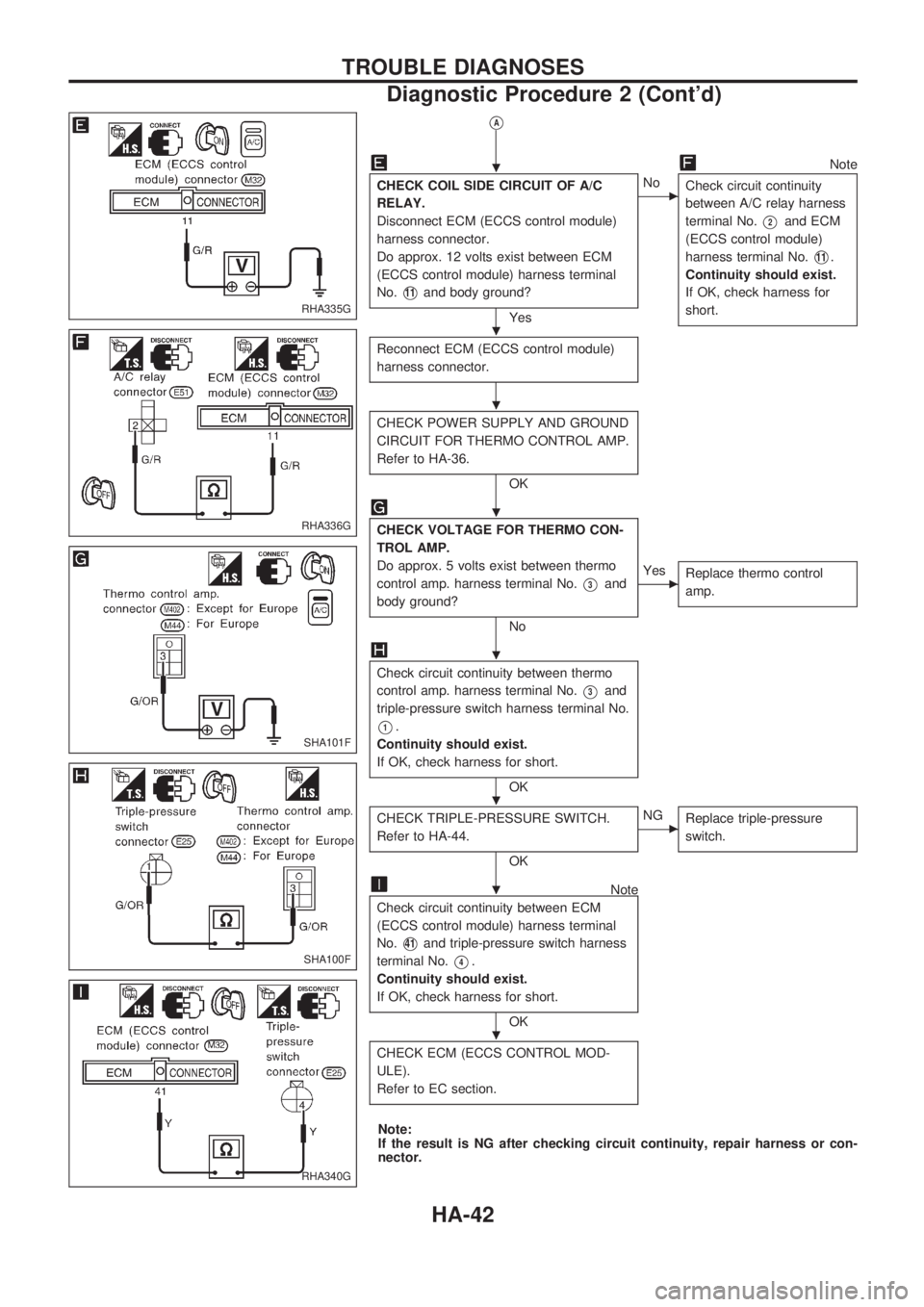
VA
Note
CHECK COIL SIDE CIRCUIT OF A/C
RELAY.
Disconnect ECM (ECCS control module)
harness connector.
Do approx. 12 volts exist between ECM
(ECCS control module) harness terminal
No.
V11and body ground?
Yes
cNo
Check circuit continuity
between A/C relay harness
terminal No.
V2and ECM
(ECCS control module)
harness terminal No.
V11.
Continuity should exist.
If OK, check harness for
short.
Reconnect ECM (ECCS control module)
harness connector.
CHECK POWER SUPPLY AND GROUND
CIRCUIT FOR THERMO CONTROL AMP.
Refer to HA-36.
OK
CHECK VOLTAGE FOR THERMO CON-
TROL AMP.
Do approx. 5 volts exist between thermo
control amp. harness terminal No.
V3and
body ground?
No
cYes
Replace thermo control
amp.
Check circuit continuity between thermo
control amp. harness terminal No.
V3and
triple-pressure switch harness terminal No.
V1.
Continuity should exist.
If OK, check harness for short.
OK
CHECK TRIPLE-PRESSURE SWITCH.
Refer to HA-44.
OK
cNG
Replace triple-pressure
switch.
Note
Check circuit continuity between ECM
(ECCS control module) harness terminal
No.
V41and triple-pressure switch harness
terminal No.
V4.
Continuity should exist.
If OK, check harness for short.
OK
CHECK ECM (ECCS CONTROL MOD-
ULE).
Refer to EC section.
Note:
If the result is NG after checking circuit continuity, repair harness or con-
nector.
RHA335G
RHA336G
SHA101F
SHA100F
RHA340G
.
.
.
.
.
.
.
.
TROUBLE DIAGNOSES
Diagnostic Procedure 2 (Cont'd)
HA-42
Page 921 of 1659
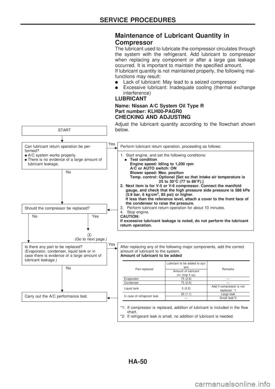
Maintenance of Lubricant Quantity in
Compressor
The lubricant used to lubricate the compressor circulates through
the system with the refrigerant. Add lubricant to compressor
when replacing any component or after a large gas leakage
occurred. It is important to maintain the specified amount.
If lubricant quantity is not maintained properly, the following mal-
functions may result:
lLack of lubricant: May lead to a seized compressor
lExcessive lubricant: Inadequate cooling (thermal exchange
interference)
LUBRICANT
Name: Nissan A/C System Oil Type R
Part number: KLH00-PAGR0
CHECKING AND ADJUSTING
Adjust the lubricant quantity according to the flowchart shown
below.
START
Can lubricant return operation be per-
formed?
lA/C system works properly.lThere is no evidence of a large amount of
lubricant leakage.
No
cYes
Perform lubricant return operation, proceeding as follows:
-----------------------------------------------------------------------------------------------------------------------------------------------------------------------------------------------------------------------------------------------------------------------------------------------------------------------------------------------------------------------------------------------------------------------------------------------------------------------------------------------------------------------------------
1. Start engine, and set the following conditions:
lTest condition
Engine speed: Idling to 1,200 rpm
A/C or AUTO switch: ON
Blower speed: Max. position
Temp. control: Optional [Set so that intake air temperature is
25 to 30ÉC (77 to 86ÉF).]
2. Next item is for V-5 or V-6 compressor. Connect the manifold
gauge, and check that the high pressure side pressure is 588 kPa
(5.9 bar, 6 kg/cm
2, 85 psi) or higher.
If less than the reference level, attach a cover to the front face of
the condenser to raise the pressure.
3. Perform lubricant return operation for about 10 minutes.
4. Stop engine.
CAUTION:
If excessive lubricant leakage is noted, do not perform the lubricant
return operation.
Should the compressor be replaced?
No Yes
b
VA(Go to next page.)
Is there any part to be replaced?
(Evaporator, condenser, liquid tank or in
case there is evidence of a large amount of
lubricant leakage.)
No
cYes
After replacing any of the following major components, add the correct
amount of lubricant to the system.
Amount of lubricant to be added
*1: If compressor is replaced, addition of lubricant is included in the flow
chart.
*2: If refrigerant leak is small, no addition of lubricant is needed.
Carry out the A/C performance test.b
Part replacedLubricant to be added to sys-
tem
Remarks
Amount of lubricant
m!(Imp fl oz)
Evaporator 75 (2.6) Ð
Condenser 75 (2.6) Ð
Liquid tank 5 (0.2)Add if compressor is not
replaced. *1
In case of refrigerant leak30 (1.1) Large leak
Ð Small leak*2
.
.
.
.
.
SERVICE PROCEDURES
HA-50
Page 972 of 1659
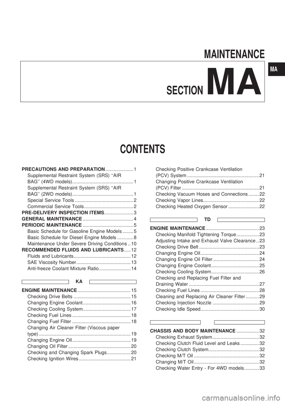
MAINTENANCE
SECTION
MA
CONTENTS
PRECAUTIONS AND PREPARATION..................... 1
Supplemental Restraint System (SRS) ``AIR
BAG'' (4WD models).............................................. 1
Supplemental Restraint System (SRS) ``AIR
BAG'' (2WD models).............................................. 1
Special Service Tools ............................................ 2
Commercial Service Tools ..................................... 2
PRE-DELIVERY INSPECTION ITEMS...................... 3
GENERAL MAINTENANCE...................................... 4
PERIODIC MAINTENANCE...................................... 5
Basic Schedule for Gasoline Engine Models ........ 5
Basic Schedule for Diesel Engine Models ............ 8
Maintenance Under Severe Driving Conditions .. 10
RECOMMENDED FLUIDS AND LUBRICANTS..... 12
Fluids and Lubricants........................................... 12
SAE Viscosity Number......................................... 13
Anti-freeze Coolant Mixture Ratio........................ 14
KA
ENGINE MAINTENANCE........................................ 15
Checking Drive Belts ........................................... 15
Changing Engine Coolant .................................... 16
Checking Cooling System.................................... 17
Checking Fuel Lines ............................................ 18
Changing Fuel Filter ............................................ 18
Changing Air Cleaner Filter (Viscous paper
type) ..................................................................... 19
Changing Engine Oil ............................................ 19
Changing Oil Filter ............................................... 20
Checking and Changing Spark Plugs.................. 20
Checking Ignition Wires ....................................... 21Checking Positive Crankcase Ventilation
(PCV) System ...................................................... 21
Changing Positive Crankcase Ventilation
(PCV) Filter .......................................................... 21
Checking Vacuum Hoses and Connections ........ 22
Checking Vapor Lines.......................................... 22
Checking Heated Oxygen Sensor ....................... 22
TD
ENGINE MAINTENANCE........................................ 23
Checking Manifold Tightening Torque ................. 23
Adjusting Intake and Exhaust Valve Clearance .. 23
Checking Drive Belt ............................................. 23
Changing Engine Oil ............................................ 24
Changing Engine Oil Filter................................... 24
Changing Engine Coolant .................................... 25
Checking Cooling System.................................... 26
Checking and Replacing Fuel Filter and
Draining Water ..................................................... 27
Checking Fuel Lines ............................................ 28
Cleaning and Replacing Air Cleaner Filter .......... 29
Checking Injection Nozzle ................................... 29
Checking Idle Speed............................................ 30
CHASSIS AND BODY MAINTENANCE................. 32
Checking Exhaust System ................................... 32
Checking Clutch Fluid Level and Leaks .............. 32
Checking Clutch System...................................... 32
Checking M/T Oil ................................................. 32
Changing M/T Oil ................................................. 32
Checking Water Entry - For 4WD models ........... 33
MA
Page 973 of 1659

Checking Transfer Fluid....................................... 33
Changing Transfer Fluid ...................................... 33
Checking Propeller Shaft ..................................... 33
Greasing Propeller Shaft ..................................... 33
Checking Differential Gear Oil ............................. 34
Changing Differential Gear Oil............................. 34
Balancing Wheels ................................................ 34
Tire Rotation ........................................................ 35
Checking Brake Fluid Level and Leaks ............... 35
Checking Brake System ...................................... 35
Changing Brake Fluid .......................................... 35
Checking Brake Booster, Vacuum Hoses,
Connections and Check Valve ............................ 36Checking Disc Brake ........................................... 36
Checking Drum Brake.......................................... 36
Checking Steering Gear and Linkage ................. 37
Checking Power Steering Fluid and Lines .......... 37
Checking Steering Gear Oil Level and Leaks ..... 38
Lubricating Hood Latches, Locks and Hinges ..... 39
Checking Seat Belts, Buckles, Retractors,
Anchors and Adjusters......................................... 40
Checking Body Corrosion .................................... 41
SERVICE DATA AND SPECIFICATIONS (SDS)... 42
Engine Maintenance (KA) .................................... 42
Engine Maintenance (TD) .................................... 42
Chassis and Body Maintenance .......................... 42
Page 988 of 1659
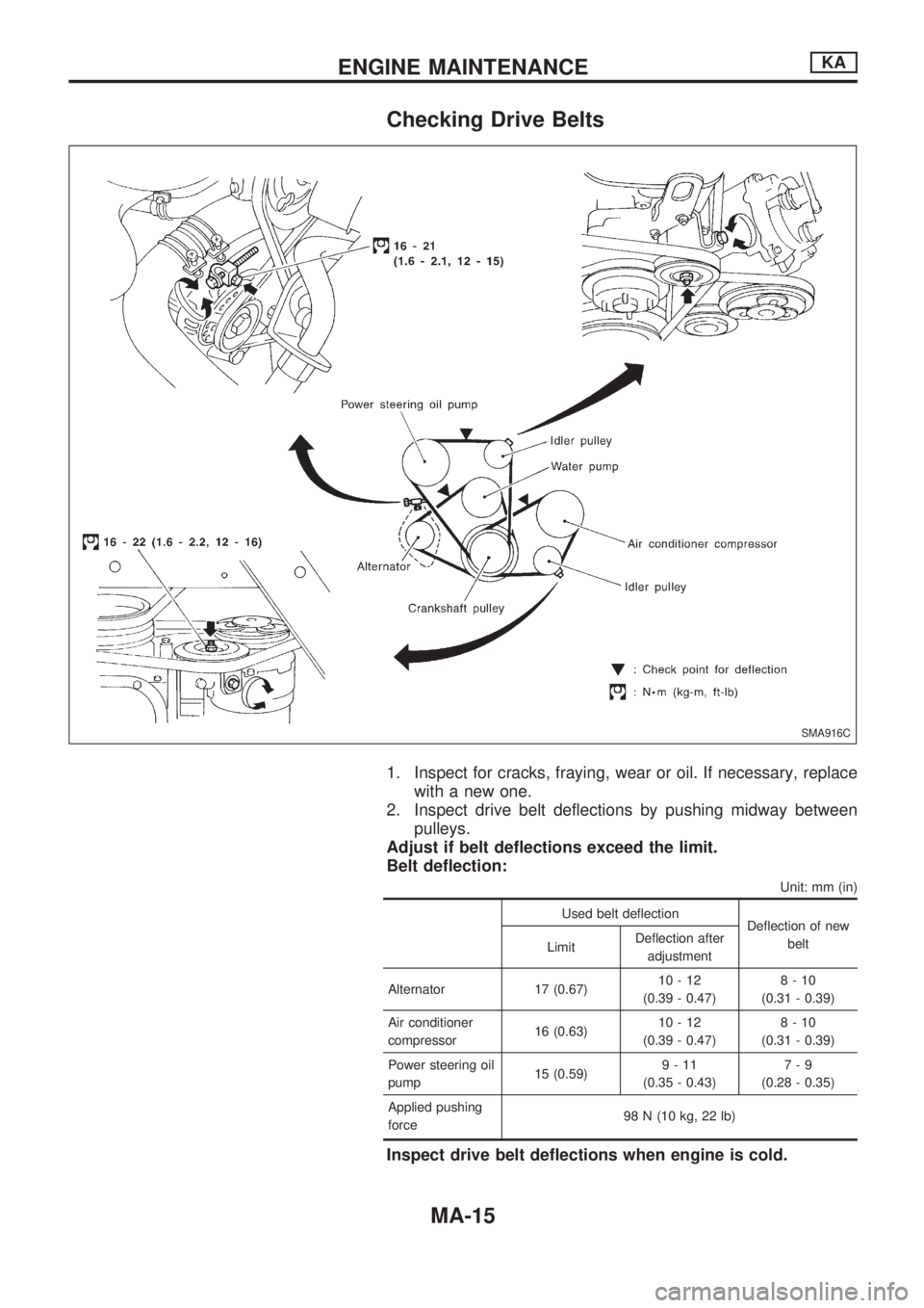
Checking Drive Belts
1. Inspect for cracks, fraying, wear or oil. If necessary, replace
with a new one.
2. Inspect drive belt deflections by pushing midway between
pulleys.
Adjust if belt deflections exceed the limit.
Belt deflection:
Unit: mm (in)
Used belt deflection
Deflection of new
belt
LimitDeflection after
adjustment
Alternator 17 (0.67)10-12
(0.39 - 0.47)8-10
(0.31 - 0.39)
Air conditioner
compressor16 (0.63)10-12
(0.39 - 0.47)8-10
(0.31 - 0.39)
Power steering oil
pump15 (0.59)9-11
(0.35 - 0.43)7-9
(0.28 - 0.35)
Applied pushing
force98 N (10 kg, 22 lb)
Inspect drive belt deflections when engine is cold.
SMA916C
ENGINE MAINTENANCEKA
MA-15
Page 993 of 1659
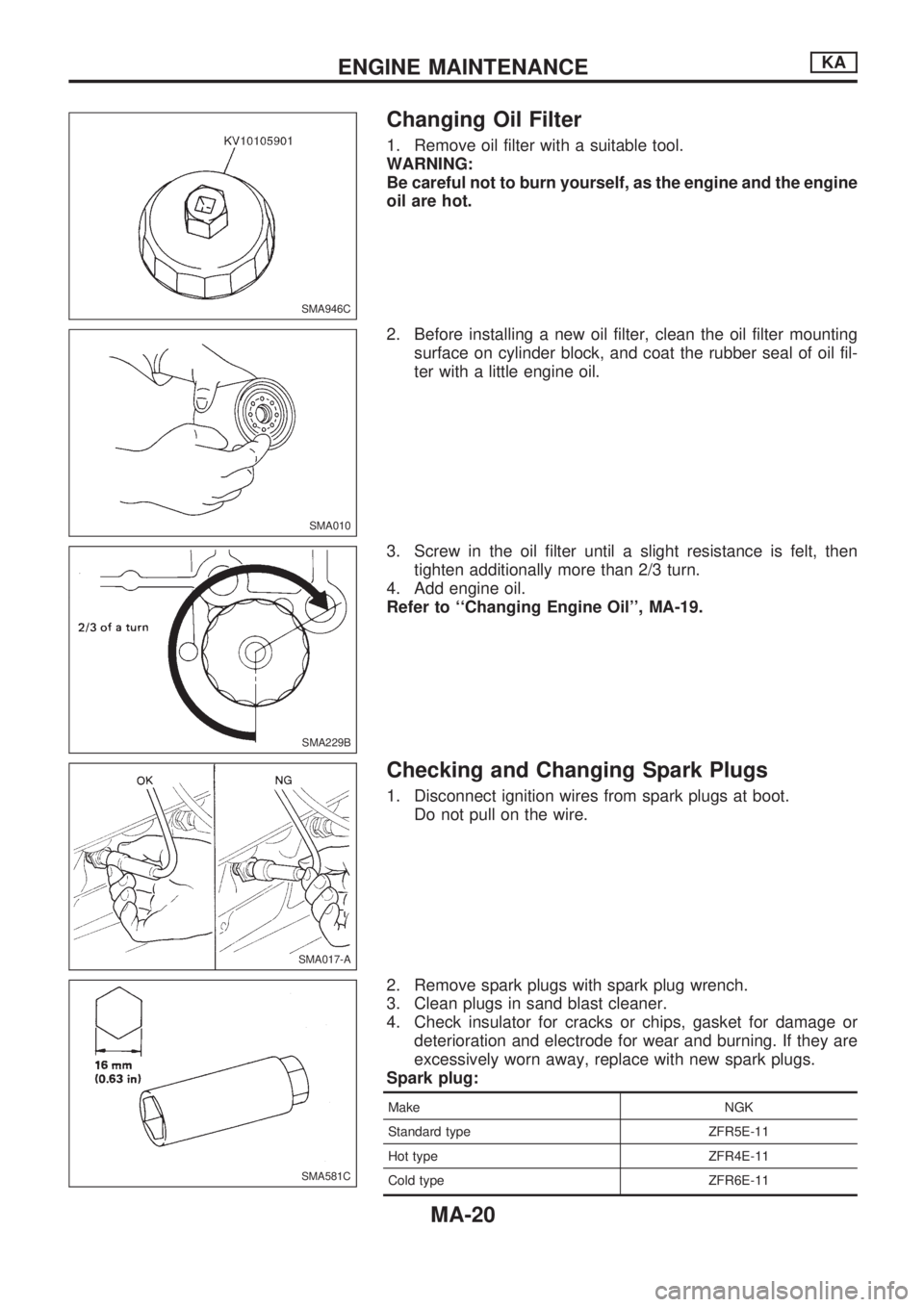
Changing Oil Filter
1. Remove oil filter with a suitable tool.
WARNING:
Be careful not to burn yourself, as the engine and the engine
oil are hot.
2. Before installing a new oil filter, clean the oil filter mounting
surface on cylinder block, and coat the rubber seal of oil fil-
ter with a little engine oil.
3. Screw in the oil filter until a slight resistance is felt, then
tighten additionally more than 2/3 turn.
4. Add engine oil.
Refer to ``Changing Engine Oil'', MA-19.
Checking and Changing Spark Plugs
1. Disconnect ignition wires from spark plugs at boot.
Do not pull on the wire.
2. Remove spark plugs with spark plug wrench.
3. Clean plugs in sand blast cleaner.
4. Check insulator for cracks or chips, gasket for damage or
deterioration and electrode for wear and burning. If they are
excessively worn away, replace with new spark plugs.
Spark plug:
Make NGK
Standard type ZFR5E-11
Hot type ZFR4E-11
Cold type ZFR6E-11
SMA946C
SMA010
SMA229B
SMA017-A
SMA581C
ENGINE MAINTENANCEKA
MA-20
Page 996 of 1659
![NISSAN PICK-UP 1998 User Guide Checking Manifold Tightening Torque
Checking should be performed while engine is cold
[approximately 20ÉC (68ÉF)].
Manifold bolts and nuts:
Intake
: 13 - 19 N´m (1.3 - 1.9 kg-m,9-14ft-lb)
Exhaust
: NISSAN PICK-UP 1998 User Guide Checking Manifold Tightening Torque
Checking should be performed while engine is cold
[approximately 20ÉC (68ÉF)].
Manifold bolts and nuts:
Intake
: 13 - 19 N´m (1.3 - 1.9 kg-m,9-14ft-lb)
Exhaust
:](/img/5/57374/w960_57374-995.png)
Checking Manifold Tightening Torque
Checking should be performed while engine is cold
[approximately 20ÉC (68ÉF)].
Manifold bolts and nuts:
Intake
: 13 - 19 N´m (1.3 - 1.9 kg-m,9-14ft-lb)
Exhaust
: 25 - 29 N´m (2.5 - 3.0 kg-m, 18 - 22 ft-lb)
Exhaust tube nuts:
: 41.2 - 48.0 N´m (4.2 - 4.9 kg-m, 30 - 35 ft-lb)
Adjusting Intake and Exhaust Valve
Clearance
Adjustment should be made while engine is warm but not
running.
1. Set No. 1 cylinder in top dead center on its compression
stroke, and adjust valve clearance
V1,V2,V3andV6.
2. Set No. 4 cylinder at top dead center on its compression
stroke, and adjust valve clearance
V4,V5,V7andV8.
Valve clearance:
Intake
V1,V3,V5andV7
0.30 - 0.40 mm (0.012 - 0.016 in)
Exhaust
V2,V4,V6andV8
0.30 - 0.40 mm (0.012 - 0.016 in)
Adjusting screw lock nuts:
: 15 - 20 N´m (1.5 - 2.0 kg-m, 11 - 14 ft-lb)
lTighten lock nuts, by fixing the adjusting screws using a
minus driver.
Checking Drive Belt
1. Inspect for cracks, fraying, wear or oil adhesion. Replace if
necessary.
The belts should not touch the bottom of the pulley groove.
2. Check drive belt deflection by pushing on the belt midway
between pulleys.
Adjust if belt deflections exceed the limit.
Unit: mm (in)
Used belt deflection
Deflection of new belt
LimitDeflection after
adjustment
Alternator 20 (0.79) 11 - 13 (0.43 - 0.51) 9 - 11 (0.35 - 0.43)
Air conditioner
compressor12 (0.47) 6 - 7.5 (0.236 - 0.295) 5 - 6.5 (0.197 - 0.256)
Power steering oil
pump15 (0.59) 8 - 9.5 (0.315 - 0.374) 7 - 8.5 (0.276 - 0.335)
Applied pushing
force98 N (10 kg, 22 lb)
Check drive belt deflections when engine is cold.
SMA653C
SMA613C
ENGINE MAINTENANCETD
MA-23