alternator belt NISSAN PICK-UP 1998 Repair Manual
[x] Cancel search | Manufacturer: NISSAN, Model Year: 1998, Model line: PICK-UP, Model: NISSAN PICK-UP 1998Pages: 1659, PDF Size: 53.39 MB
Page 426 of 1659
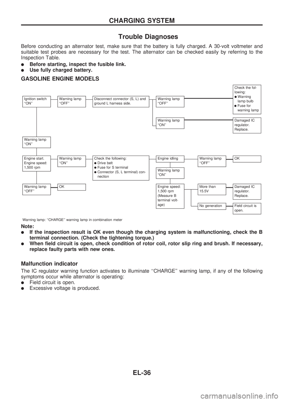
Trouble Diagnoses
Before conducting an alternator test, make sure that the battery is fully charged. A 30-volt voltmeter and
suitable test probes are necessary for the test. The alternator can be checked easily by referring to the
Inspection Table.
lBefore starting, inspect the fusible link.
lUse fully charged battery.
GASOLINE ENGINE MODELS
Check the fol-
lowing:
lWarning
lamp bulb
lFuse for
warning lamp
Ignition switch
``ON''Warning lamp
``OFF''Disconnect connector (S, L) and
ground L harness side.Warning lamp
``OFF''
Warning lamp
``ON''Damaged IC
regulator.
Replace.
Warning lamp
``ON''
Engine start.
Engine speed:
1,500 rpmWarning lamp
``ON''Check the following:lDrive beltlFuse for S terminallConnector (S, L terminal) con-
nection
Engine idlingWarning lamp
``OFF''OK
Warning lamp
``ON''
Warning lamp
``OFF''OKEngine speed:
1,500 rpm
(Measure B
terminal volt-
age)More than
15.5VDamaged IC
regulator.
Replace.
No generationField circuit is
open.
Warning lamp: ``CHARGE'' warning lamp in combination meter
Note:
lIf the inspection result is OK even though the charging system is malfunctioning, check the B
terminal connection. (Check the tightening torque.)
lWhen field circuit is open, check condition of rotor coil, rotor slip ring and brush. If necessary,
replace faulty parts with new ones.
Malfunction indicator
The IC regulator warning function activates to illuminate ``CHARGE'' warning lamp, if any of the following
symptoms occur while alternator is operating:
lField circuit is open.
lExcessive voltage is produced.
CHARGING SYSTEM
EL-36
Page 658 of 1659
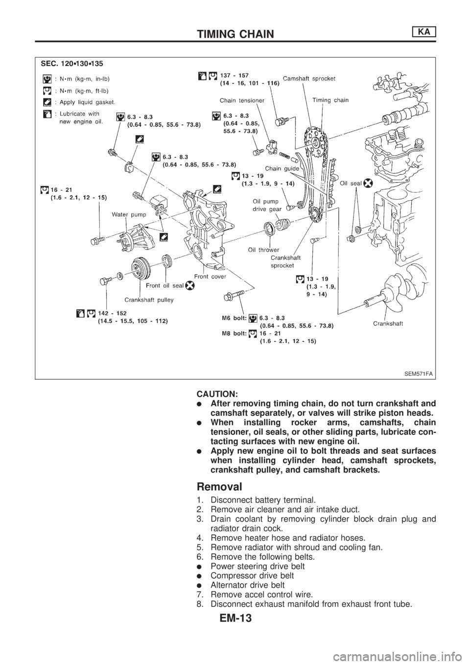
CAUTION:
lAfter removing timing chain, do not turn crankshaft and
camshaft separately, or valves will strike piston heads.
lWhen installing rocker arms, camshafts, chain
tensioner, oil seals, or other sliding parts, lubricate con-
tacting surfaces with new engine oil.
lApply new engine oil to bolt threads and seat surfaces
when installing cylinder head, camshaft sprockets,
crankshaft pulley, and camshaft brackets.
Removal
1. Disconnect battery terminal.
2. Remove air cleaner and air intake duct.
3. Drain coolant by removing cylinder block drain plug and
radiator drain cock.
4. Remove heater hose and radiator hoses.
5. Remove radiator with shroud and cooling fan.
6. Remove the following belts.
lPower steering drive belt
lCompressor drive belt
lAlternator drive belt
7. Remove accel control wire.
8. Disconnect exhaust manifold from exhaust front tube.
SEM571FA
TIMING CHAINKA
EM-13
Page 682 of 1659
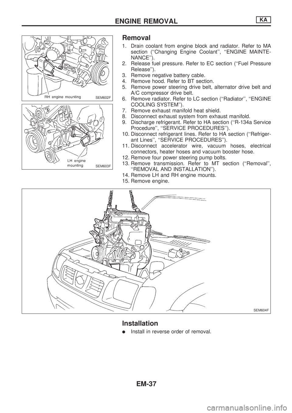
Removal
1. Drain coolant from engine block and radiator. Refer to MA
section (``Changing Engine Coolant'', ``ENGINE MAINTE-
NANCE'').
2. Release fuel pressure. Refer to EC section (``Fuel Pressure
Release'').
3. Remove negative battery cable.
4. Remove hood. Refer to BT section.
5. Remove power steering drive belt, alternator drive belt and
A/C compressor drive belt.
6. Remove radiator. Refer to LC section (``Radiator'', ``ENGINE
COOLING SYSTEM'').
7. Remove exhaust manifold heat shield.
8. Disconnect exhaust system from exhaust manifold.
9. Discharge refrigerant. Refer to HA section (``R-134a Service
Procedure'', ``SERVICE PROCEDURES'').
10. Disconnect refrigerant lines. Refer to HA section (``Refriger-
ant Lines'', ``SERVICE PROCEDURES'').
11. Disconnect accelerator wire, vacuum hoses, electrical
connectors, heater hoses and vacuum booster hose.
12. Remove four power steering pump bolts.
13. Remove transmission. Refer to MT section (``Removal'',
``REMOVAL AND INSTALLATION'').
14. Remove LH and RH engine mounts.
15. Remove engine.
Installation
lInstall in reverse order of removal.
SEM602F
SEM603F
SEM604F
ENGINE REMOVALKA
EM-37
Page 988 of 1659
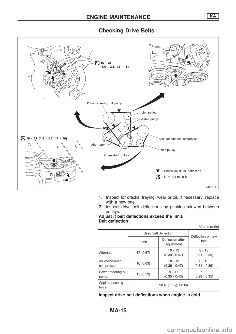
Checking Drive Belts
1. Inspect for cracks, fraying, wear or oil. If necessary, replace
with a new one.
2. Inspect drive belt deflections by pushing midway between
pulleys.
Adjust if belt deflections exceed the limit.
Belt deflection:
Unit: mm (in)
Used belt deflection
Deflection of new
belt
LimitDeflection after
adjustment
Alternator 17 (0.67)10-12
(0.39 - 0.47)8-10
(0.31 - 0.39)
Air conditioner
compressor16 (0.63)10-12
(0.39 - 0.47)8-10
(0.31 - 0.39)
Power steering oil
pump15 (0.59)9-11
(0.35 - 0.43)7-9
(0.28 - 0.35)
Applied pushing
force98 N (10 kg, 22 lb)
Inspect drive belt deflections when engine is cold.
SMA916C
ENGINE MAINTENANCEKA
MA-15
Page 996 of 1659
![NISSAN PICK-UP 1998 Repair Manual Checking Manifold Tightening Torque
Checking should be performed while engine is cold
[approximately 20ÉC (68ÉF)].
Manifold bolts and nuts:
Intake
: 13 - 19 N´m (1.3 - 1.9 kg-m,9-14ft-lb)
Exhaust
: NISSAN PICK-UP 1998 Repair Manual Checking Manifold Tightening Torque
Checking should be performed while engine is cold
[approximately 20ÉC (68ÉF)].
Manifold bolts and nuts:
Intake
: 13 - 19 N´m (1.3 - 1.9 kg-m,9-14ft-lb)
Exhaust
:](/img/5/57374/w960_57374-995.png)
Checking Manifold Tightening Torque
Checking should be performed while engine is cold
[approximately 20ÉC (68ÉF)].
Manifold bolts and nuts:
Intake
: 13 - 19 N´m (1.3 - 1.9 kg-m,9-14ft-lb)
Exhaust
: 25 - 29 N´m (2.5 - 3.0 kg-m, 18 - 22 ft-lb)
Exhaust tube nuts:
: 41.2 - 48.0 N´m (4.2 - 4.9 kg-m, 30 - 35 ft-lb)
Adjusting Intake and Exhaust Valve
Clearance
Adjustment should be made while engine is warm but not
running.
1. Set No. 1 cylinder in top dead center on its compression
stroke, and adjust valve clearance
V1,V2,V3andV6.
2. Set No. 4 cylinder at top dead center on its compression
stroke, and adjust valve clearance
V4,V5,V7andV8.
Valve clearance:
Intake
V1,V3,V5andV7
0.30 - 0.40 mm (0.012 - 0.016 in)
Exhaust
V2,V4,V6andV8
0.30 - 0.40 mm (0.012 - 0.016 in)
Adjusting screw lock nuts:
: 15 - 20 N´m (1.5 - 2.0 kg-m, 11 - 14 ft-lb)
lTighten lock nuts, by fixing the adjusting screws using a
minus driver.
Checking Drive Belt
1. Inspect for cracks, fraying, wear or oil adhesion. Replace if
necessary.
The belts should not touch the bottom of the pulley groove.
2. Check drive belt deflection by pushing on the belt midway
between pulleys.
Adjust if belt deflections exceed the limit.
Unit: mm (in)
Used belt deflection
Deflection of new belt
LimitDeflection after
adjustment
Alternator 20 (0.79) 11 - 13 (0.43 - 0.51) 9 - 11 (0.35 - 0.43)
Air conditioner
compressor12 (0.47) 6 - 7.5 (0.236 - 0.295) 5 - 6.5 (0.197 - 0.256)
Power steering oil
pump15 (0.59) 8 - 9.5 (0.315 - 0.374) 7 - 8.5 (0.276 - 0.335)
Applied pushing
force98 N (10 kg, 22 lb)
Check drive belt deflections when engine is cold.
SMA653C
SMA613C
ENGINE MAINTENANCETD
MA-23
Page 1015 of 1659
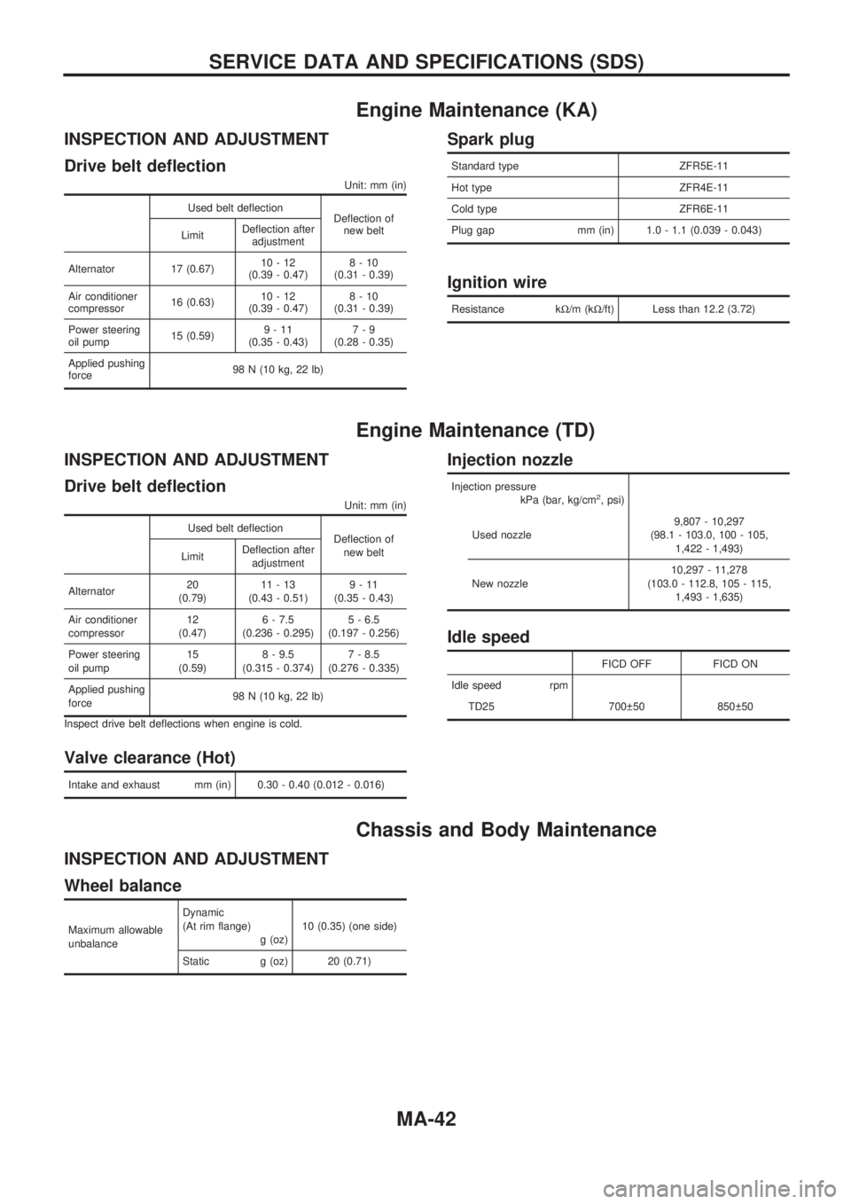
Engine Maintenance (KA)
INSPECTION AND ADJUSTMENT
Drive belt deflection
Unit: mm (in)
Used belt deflection
Deflection of
new belt
LimitDeflection after
adjustment
Alternator 17 (0.67)10-12
(0.39 - 0.47)8-10
(0.31 - 0.39)
Air conditioner
compressor16 (0.63)10-12
(0.39 - 0.47)8-10
(0.31 - 0.39)
Power steering
oil pump15 (0.59)9-11
(0.35 - 0.43)7-9
(0.28 - 0.35)
Applied pushing
force98 N (10 kg, 22 lb)
Spark plug
Standard type ZFR5E-11
Hot type ZFR4E-11
Cold type ZFR6E-11
Plug gap mm (in) 1.0 - 1.1 (0.039 - 0.043)
Ignition wire
Resistance kW/m (kW/ft) Less than 12.2 (3.72)
Engine Maintenance (TD)
INSPECTION AND ADJUSTMENT
Drive belt deflection
Unit: mm (in)
Used belt deflection
Deflection of
new belt
LimitDeflection after
adjustment
Alternator20
(0.79)11-13
(0.43 - 0.51)9-11
(0.35 - 0.43)
Air conditioner
compressor12
(0.47)6 - 7.5
(0.236 - 0.295)5 - 6.5
(0.197 - 0.256)
Power steering
oil pump15
(0.59)8 - 9.5
(0.315 - 0.374)7 - 8.5
(0.276 - 0.335)
Applied pushing
force98 N (10 kg, 22 lb)
Inspect drive belt deflections when engine is cold.
Valve clearance (Hot)
Intake and exhaust mm (in) 0.30 - 0.40 (0.012 - 0.016)
Injection nozzle
Injection pressure
kPa (bar, kg/cm2, psi)
Used nozzle9,807 - 10,297
(98.1 - 103.0, 100 - 105,
1,422 - 1,493)
New nozzle10,297 - 11,278
(103.0 - 112.8, 105 - 115,
1,493 - 1,635)
Idle speed
FICD OFF FICD ON
Idle speed rpm
TD25 700 50 850 50
Chassis and Body Maintenance
INSPECTION AND ADJUSTMENT
Wheel balance
Maximum allowable
unbalanceDynamic
(At rim flange)
g (oz)10 (0.35) (one side)
Static g (oz) 20 (0.71)
SERVICE DATA AND SPECIFICATIONS (SDS)
MA-42
Page 1334 of 1659
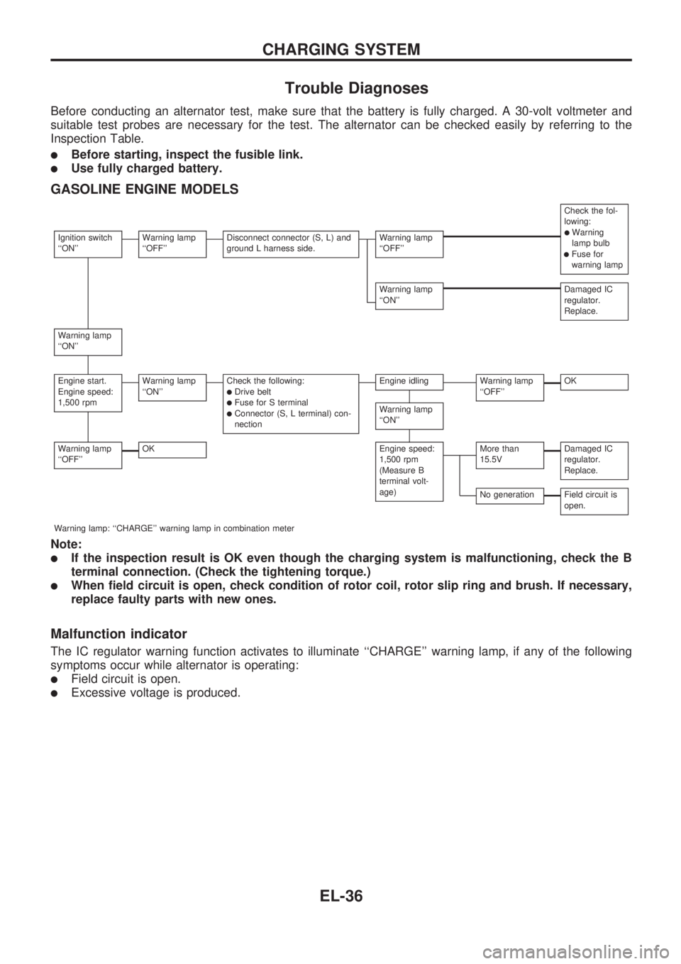
Trouble Diagnoses
Before conducting an alternator test, make sure that the battery is fully charged. A 30-volt voltmeter and
suitable test probes are necessary for the test. The alternator can be checked easily by referring to the
Inspection Table.
lBefore starting, inspect the fusible link.
lUse fully charged battery.
GASOLINE ENGINE MODELS
Check the fol-
lowing:
lWarning
lamp bulb
lFuse for
warning lamp
Ignition switch
``ON''Warning lamp
``OFF''Disconnect connector (S, L) and
ground L harness side.Warning lamp
``OFF''
Warning lamp
``ON''Damaged IC
regulator.
Replace.
Warning lamp
``ON''
Engine start.
Engine speed:
1,500 rpmWarning lamp
``ON''Check the following:lDrive beltlFuse for S terminallConnector (S, L terminal) con-
nection
Engine idlingWarning lamp
``OFF''OK
Warning lamp
``ON''
Warning lamp
``OFF''OKEngine speed:
1,500 rpm
(Measure B
terminal volt-
age)More than
15.5VDamaged IC
regulator.
Replace.
No generationField circuit is
open.
Warning lamp: ``CHARGE'' warning lamp in combination meter
Note:
lIf the inspection result is OK even though the charging system is malfunctioning, check the B
terminal connection. (Check the tightening torque.)
lWhen field circuit is open, check condition of rotor coil, rotor slip ring and brush. If necessary,
replace faulty parts with new ones.
Malfunction indicator
The IC regulator warning function activates to illuminate ``CHARGE'' warning lamp, if any of the following
symptoms occur while alternator is operating:
lField circuit is open.
lExcessive voltage is produced.
CHARGING SYSTEM
EL-36
Page 1566 of 1659
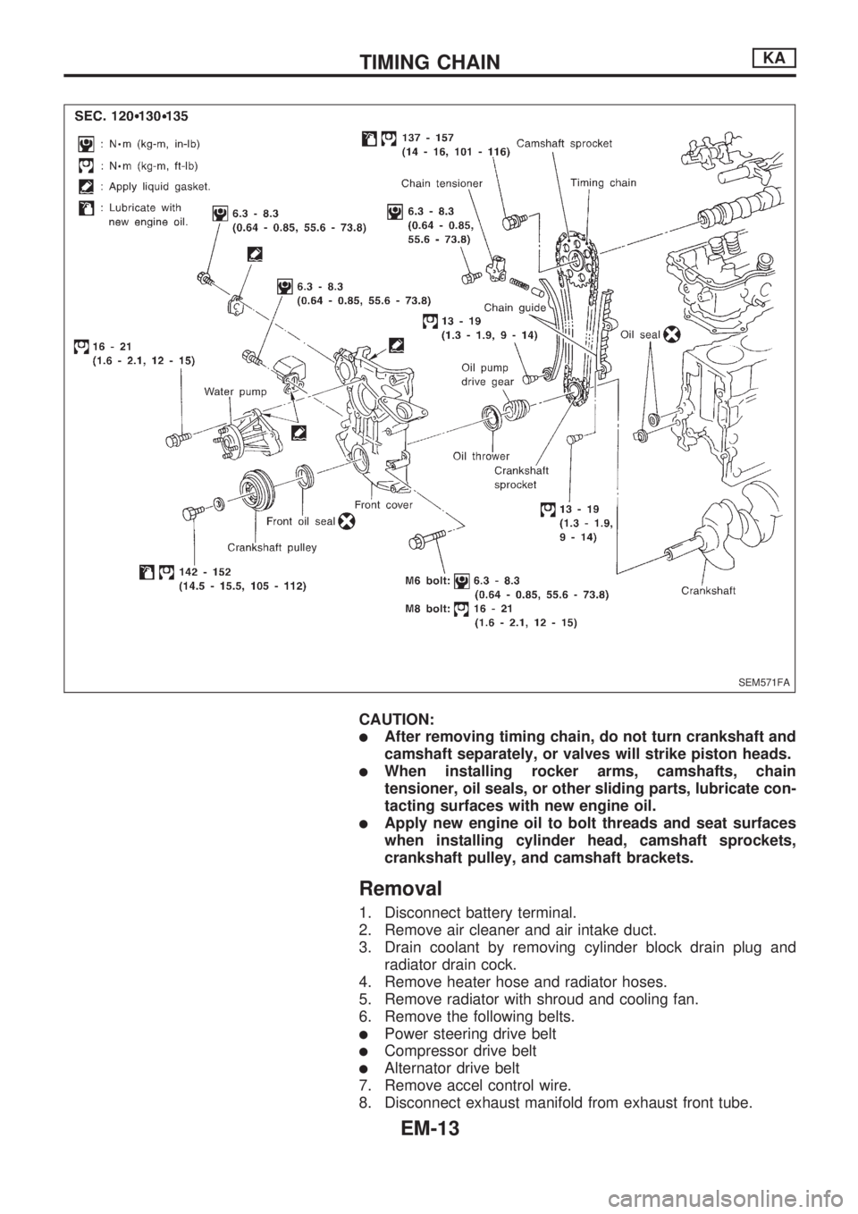
CAUTION:
lAfter removing timing chain, do not turn crankshaft and
camshaft separately, or valves will strike piston heads.
lWhen installing rocker arms, camshafts, chain
tensioner, oil seals, or other sliding parts, lubricate con-
tacting surfaces with new engine oil.
lApply new engine oil to bolt threads and seat surfaces
when installing cylinder head, camshaft sprockets,
crankshaft pulley, and camshaft brackets.
Removal
1. Disconnect battery terminal.
2. Remove air cleaner and air intake duct.
3. Drain coolant by removing cylinder block drain plug and
radiator drain cock.
4. Remove heater hose and radiator hoses.
5. Remove radiator with shroud and cooling fan.
6. Remove the following belts.
lPower steering drive belt
lCompressor drive belt
lAlternator drive belt
7. Remove accel control wire.
8. Disconnect exhaust manifold from exhaust front tube.
SEM571FA
TIMING CHAINKA
EM-13
Page 1590 of 1659
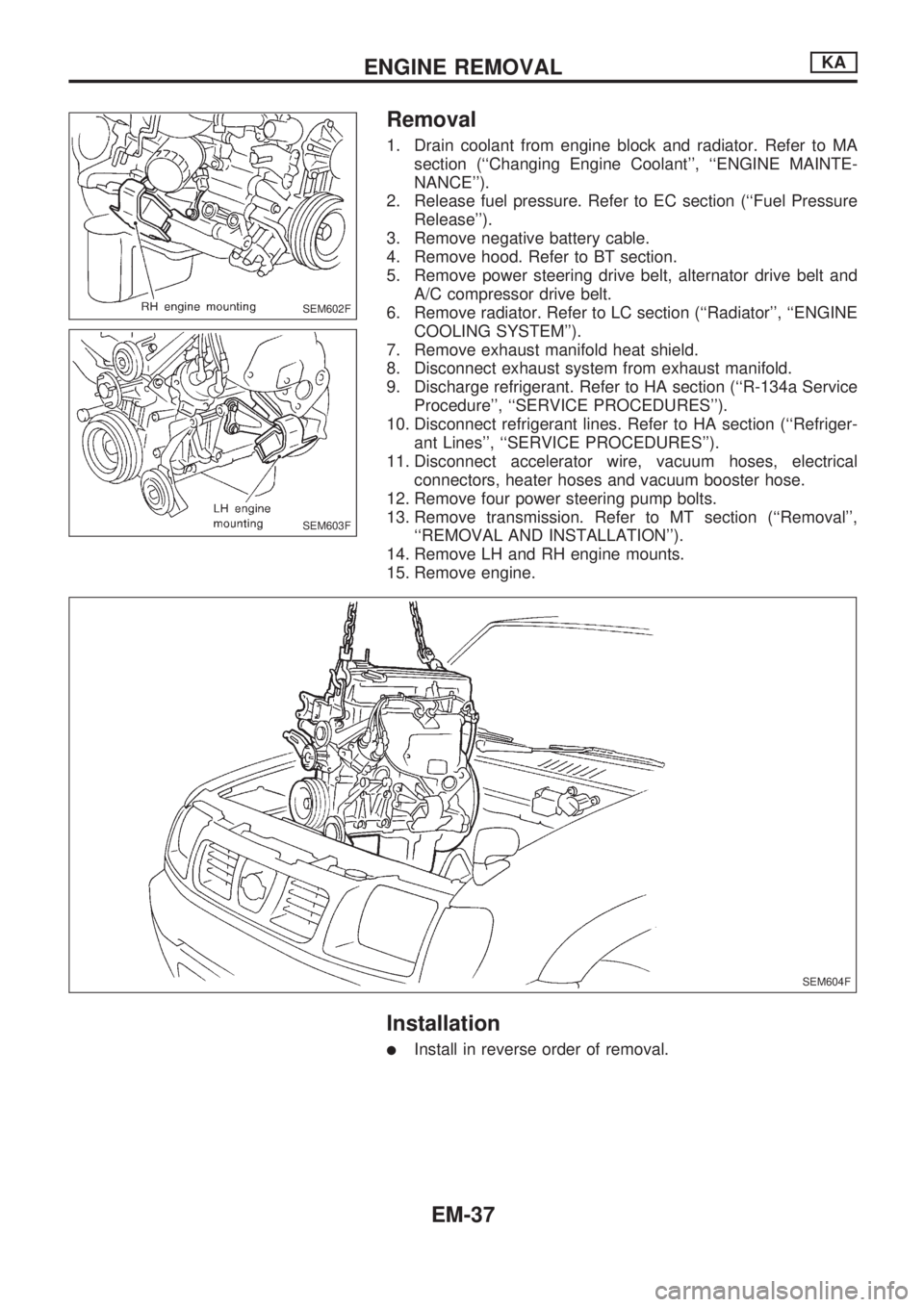
Removal
1. Drain coolant from engine block and radiator. Refer to MA
section (``Changing Engine Coolant'', ``ENGINE MAINTE-
NANCE'').
2. Release fuel pressure. Refer to EC section (``Fuel Pressure
Release'').
3. Remove negative battery cable.
4. Remove hood. Refer to BT section.
5. Remove power steering drive belt, alternator drive belt and
A/C compressor drive belt.
6. Remove radiator. Refer to LC section (``Radiator'', ``ENGINE
COOLING SYSTEM'').
7. Remove exhaust manifold heat shield.
8. Disconnect exhaust system from exhaust manifold.
9. Discharge refrigerant. Refer to HA section (``R-134a Service
Procedure'', ``SERVICE PROCEDURES'').
10. Disconnect refrigerant lines. Refer to HA section (``Refriger-
ant Lines'', ``SERVICE PROCEDURES'').
11. Disconnect accelerator wire, vacuum hoses, electrical
connectors, heater hoses and vacuum booster hose.
12. Remove four power steering pump bolts.
13. Remove transmission. Refer to MT section (``Removal'',
``REMOVAL AND INSTALLATION'').
14. Remove LH and RH engine mounts.
15. Remove engine.
Installation
lInstall in reverse order of removal.
SEM602F
SEM603F
SEM604F
ENGINE REMOVALKA
EM-37