temperature sensor NISSAN PICK-UP 1998 Service Manual
[x] Cancel search | Manufacturer: NISSAN, Model Year: 1998, Model line: PICK-UP, Model: NISSAN PICK-UP 1998Pages: 1659, PDF Size: 53.39 MB
Page 643 of 1659
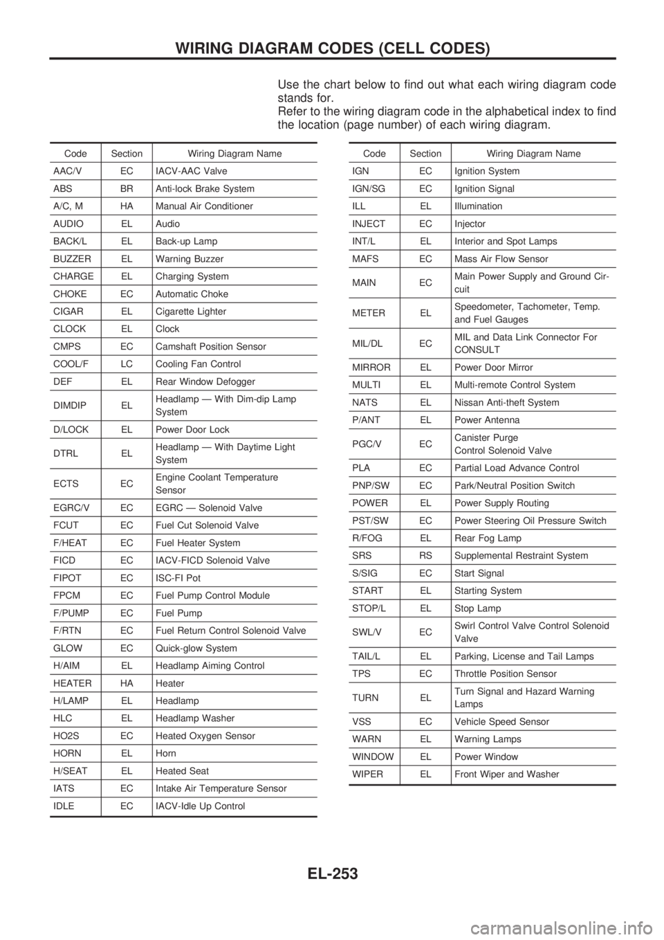
Use the chart below to find out what each wiring diagram code
stands for.
Refer to the wiring diagram code in the alphabetical index to find
the location (page number) of each wiring diagram.
Code Section Wiring Diagram Name
AAC/V EC IACV-AAC Valve
ABS BR Anti-lock Brake System
A/C, M HA Manual Air Conditioner
AUDIO EL Audio
BACK/L EL Back-up Lamp
BUZZER EL Warning Buzzer
CHARGE EL Charging System
CHOKE EC Automatic Choke
CIGAR EL Cigarette Lighter
CLOCK EL Clock
CMPS EC Camshaft Position Sensor
COOL/F LC Cooling Fan Control
DEF EL Rear Window Defogger
DIMDIP ELHeadlamp Ð With Dim-dip Lamp
System
D/LOCK EL Power Door Lock
DTRL ELHeadlamp Ð With Daytime Light
System
ECTS ECEngine Coolant Temperature
Sensor
EGRC/V EC EGRC Ð Solenoid Valve
FCUT EC Fuel Cut Solenoid Valve
F/HEAT EC Fuel Heater System
FICD EC IACV-FICD Solenoid Valve
FIPOT EC ISC-FI Pot
FPCM EC Fuel Pump Control Module
F/PUMP EC Fuel Pump
F/RTN EC Fuel Return Control Solenoid Valve
GLOW EC Quick-glow System
H/AIM EL Headlamp Aiming Control
HEATER HA Heater
H/LAMP EL Headlamp
HLC EL Headlamp Washer
HO2S EC Heated Oxygen Sensor
HORN EL Horn
H/SEAT EL Heated Seat
IATS EC Intake Air Temperature Sensor
IDLE EC IACV-Idle Up ControlCode Section Wiring Diagram Name
IGN EC Ignition System
IGN/SG EC Ignition Signal
ILL EL Illumination
INJECT EC Injector
INT/L EL Interior and Spot Lamps
MAFS EC Mass Air Flow Sensor
MAIN ECMain Power Supply and Ground Cir-
cuit
METER ELSpeedometer, Tachometer, Temp.
and Fuel Gauges
MIL/DL ECMIL and Data Link Connector For
CONSULT
MIRROR EL Power Door Mirror
MULTI EL Multi-remote Control System
NATS EL Nissan Anti-theft System
P/ANT EL Power Antenna
PGC/V ECCanister Purge
Control Solenoid Valve
PLA EC Partial Load Advance Control
PNP/SW EC Park/Neutral Position Switch
POWER EL Power Supply Routing
PST/SW EC Power Steering Oil Pressure Switch
R/FOG EL Rear Fog Lamp
SRS RS Supplemental Restraint System
S/SIG EC Start Signal
START EL Starting System
STOP/L EL Stop Lamp
SWL/V ECSwirl Control Valve Control Solenoid
Valve
TAIL/L EL Parking, License and Tail Lamps
TPS EC Throttle Position Sensor
TURN ELTurn Signal and Hazard Warning
Lamps
VSS EC Vehicle Speed Sensor
WARN EL Warning Lamps
WINDOW EL Power Window
WIPER EL Front Wiper and Washer
WIRING DIAGRAM CODES (CELL CODES)
EL-253
Page 808 of 1659
lAfter disconnecting vacuum or air hoses, attach a tag to
indicate the proper connection.
lUse only the fluids and lubricants specified in this manual.
lUse approved bonding agent, sealants or their equivalents
when required.
lUse tools and recommended special tools where specified
for safe and efficient service repairs.
lWhen repairing the fuel, oil, water, vacuum or exhaust
systems, check all affected lines for leaks.
lDispose of drained oil or the solvent used for cleaning parts
in an appropriate manner.
WARNING:
To prevent ECM from storing the diagnostic trouble codes,
do not carelessly disconnect the harness connectors which
are related to the ECCS system and TCM (Transmission
Control Module) system. The connectors should be discon-
nected only when working according to the WORK FLOW of
TROUBLE DIAGNOSES in EC section.
Precautions for Multiport Fuel Injection
System or ECCS Engine
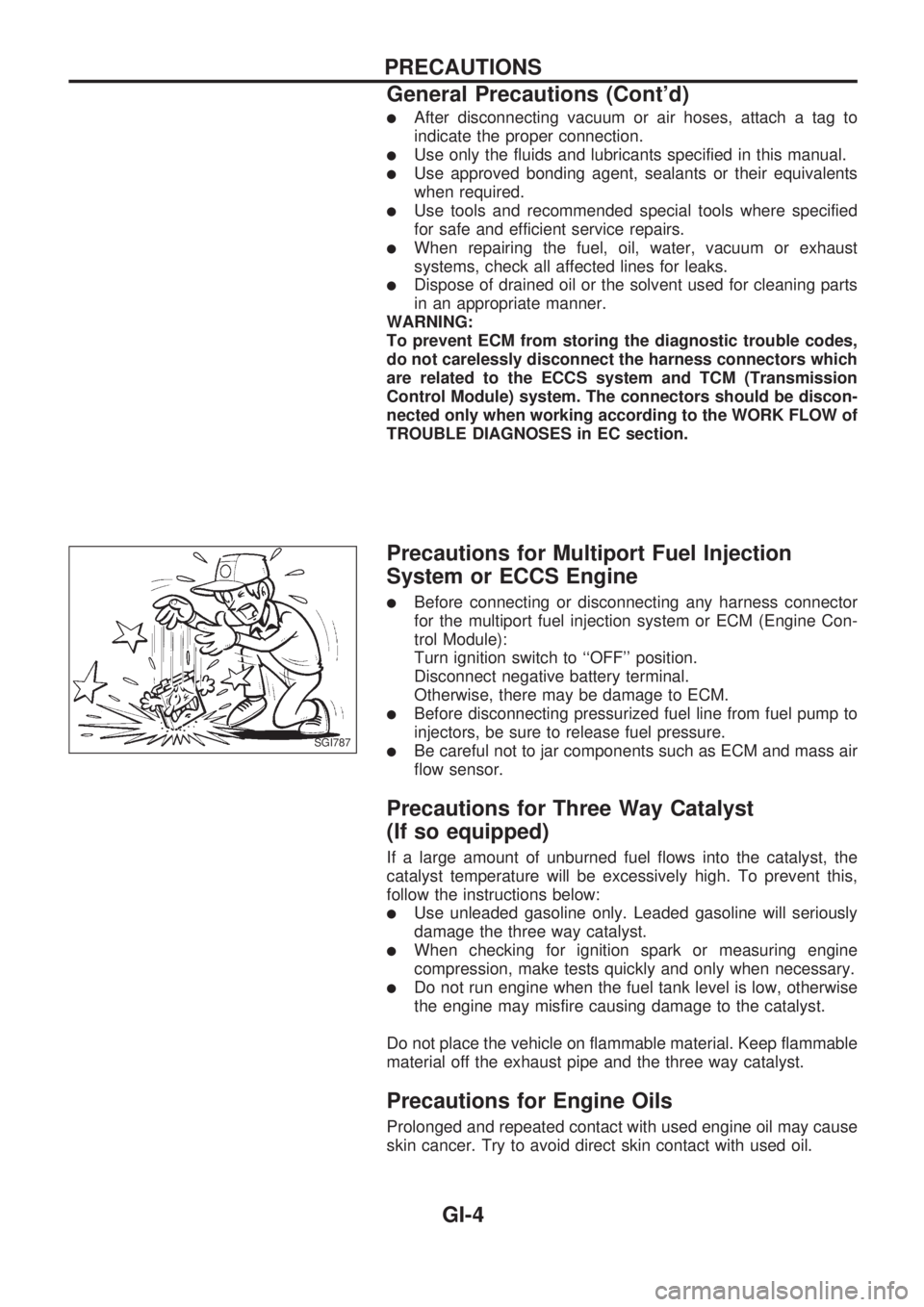
lBefore connecting or disconnecting any harness connector
for the multiport fuel injection system or ECM (Engine Con-
trol Module):
Turn ignition switch to ``OFF'' position.
Disconnect negative battery terminal.
Otherwise, there may be damage to ECM.
lBefore disconnecting pressurized fuel line from fuel pump to
injectors, be sure to release fuel pressure.
lBe careful not to jar components such as ECM and mass air
flow sensor.
Precautions for Three Way Catalyst
(If so equipped)
If a large amount of unburned fuel flows into the catalyst, the
catalyst temperature will be excessively high. To prevent this,
follow the instructions below:
lUse unleaded gasoline only. Leaded gasoline will seriously
damage the three way catalyst.
lWhen checking for ignition spark or measuring engine
compression, make tests quickly and only when necessary.
lDo not run engine when the fuel tank level is low, otherwise
the engine may misfire causing damage to the catalyst.
Do not place the vehicle on flammable material. Keep flammable
material off the exhaust pipe and the three way catalyst.
Precautions for Engine Oils
Prolonged and repeated contact with used engine oil may cause
skin cancer. Try to avoid direct skin contact with used oil.
SGI787
PRECAUTIONS
General Precautions (Cont'd)
GI-4
Page 859 of 1659
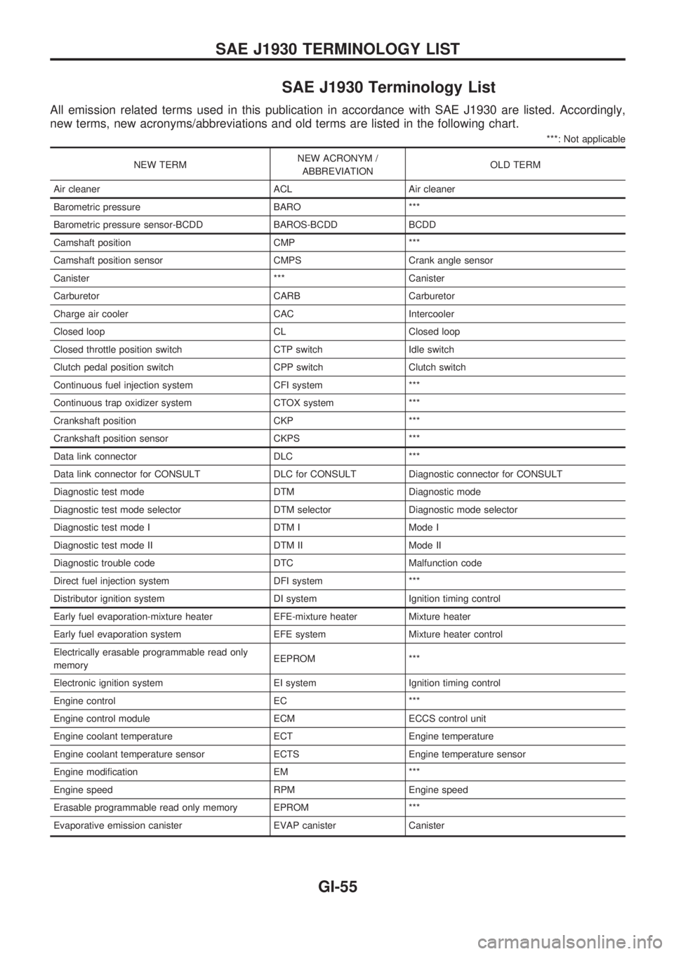
SAE J1930 Terminology List
All emission related terms used in this publication in accordance with SAE J1930 are listed. Accordingly,
new terms, new acronyms/abbreviations and old terms are listed in the following chart.
***: Not applicable
NEW TERMNEW ACRONYM /
ABBREVIATIONOLD TERM
Air cleaner ACL Air cleaner
Barometric pressure BARO ***
Barometric pressure sensor-BCDD BAROS-BCDD BCDD
Camshaft position CMP ***
Camshaft position sensor CMPS Crank angle sensor
Canister *** Canister
Carburetor CARB Carburetor
Charge air cooler CAC Intercooler
Closed loop CL Closed loop
Closed throttle position switch CTP switch Idle switch
Clutch pedal position switch CPP switch Clutch switch
Continuous fuel injection system CFI system ***
Continuous trap oxidizer system CTOX system ***
Crankshaft position CKP ***
Crankshaft position sensor CKPS ***
Data link connector DLC ***
Data link connector for CONSULT DLC for CONSULT Diagnostic connector for CONSULT
Diagnostic test mode DTM Diagnostic mode
Diagnostic test mode selector DTM selector Diagnostic mode selector
Diagnostic test mode I DTM I Mode I
Diagnostic test mode II DTM II Mode II
Diagnostic trouble code DTC Malfunction code
Direct fuel injection system DFI system ***
Distributor ignition system DI system Ignition timing control
Early fuel evaporation-mixture heater EFE-mixture heater Mixture heater
Early fuel evaporation system EFE system Mixture heater control
Electrically erasable programmable read only
memoryEEPROM ***
Electronic ignition system EI system Ignition timing control
Engine control EC ***
Engine control module ECM ECCS control unit
Engine coolant temperature ECT Engine temperature
Engine coolant temperature sensor ECTS Engine temperature sensor
Engine modification EM ***
Engine speed RPM Engine speed
Erasable programmable read only memory EPROM ***
Evaporative emission canister EVAP canister Canister
SAE J1930 TERMINOLOGY LIST
GI-55
Page 860 of 1659
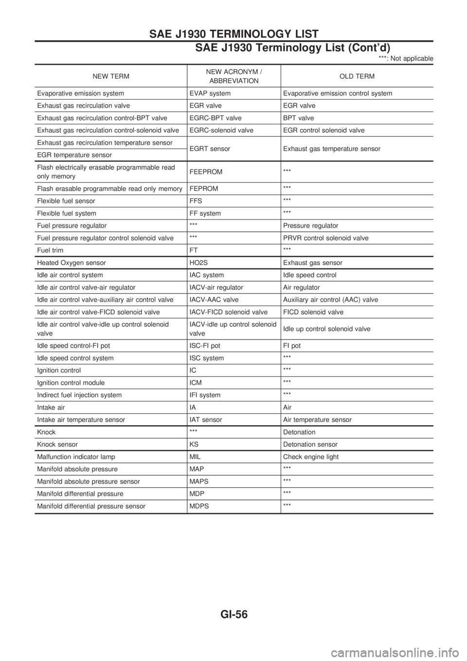
***: Not applicable
NEW TERMNEW ACRONYM /
ABBREVIATIONOLD TERM
Evaporative emission system EVAP system Evaporative emission control system
Exhaust gas recirculation valve EGR valve EGR valve
Exhaust gas recirculation control-BPT valve EGRC-BPT valve BPT valve
Exhaust gas recirculation control-solenoid valve EGRC-solenoid valve EGR control solenoid valve
Exhaust gas recirculation temperature sensor
EGRT sensor Exhaust gas temperature sensor
EGR temperature sensor
Flash electrically erasable programmable read
only memoryFEEPROM ***
Flash erasable programmable read only memory FEPROM ***
Flexible fuel sensor FFS ***
Flexible fuel system FF system ***
Fuel pressure regulator *** Pressure regulator
Fuel pressure regulator control solenoid valve *** PRVR control solenoid valve
Fuel trim FT ***
Heated Oxygen sensor HO2S Exhaust gas sensor
Idle air control system IAC system Idle speed control
Idle air control valve-air regulator IACV-air regulator Air regulator
Idle air control valve-auxiliary air control valve IACV-AAC valve Auxiliary air control (AAC) valve
Idle air control valve-FICD solenoid valve IACV-FICD solenoid valve FICD solenoid valve
Idle air control valve-idle up control solenoid
valveIACV-idle up control solenoid
valveIdle up control solenoid valve
Idle speed control-FI pot ISC-FI pot FI pot
Idle speed control system ISC system ***
Ignition control IC ***
Ignition control module ICM ***
Indirect fuel injection system IFI system ***
Intake air IA Air
Intake air temperature sensor IAT sensor Air temperature sensor
Knock *** Detonation
Knock sensor KS Detonation sensor
Malfunction indicator lamp MIL Check engine light
Manifold absolute pressure MAP ***
Manifold absolute pressure sensor MAPS ***
Manifold differential pressure MDP ***
Manifold differential pressure sensor MDPS ***
SAE J1930 TERMINOLOGY LIST
SAE J1930 Terminology List (Cont'd)
GI-56
Page 861 of 1659
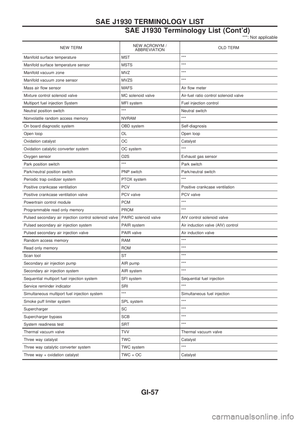
***: Not applicable
NEW TERMNEW ACRONYM /
ABBREVIATIONOLD TERM
Manifold surface temperature MST ***
Manifold surface temperature sensor MSTS ***
Manifold vacuum zone MVZ ***
Manifold vacuum zone sensor MVZS ***
Mass air flow sensor MAFS Air flow meter
Mixture control solenoid valve MC solenoid valve Air-fuel ratio control solenoid valve
Multiport fuel injection System MFI system Fuel injection control
Neutral position switch *** Neutral switch
Nonvolatile random access memory NVRAM ***
On board diagnostic system OBD system Self-diagnosis
Open loop OL Open loop
Oxidation catalyst OC Catalyst
Oxidation catalytic converter system OC system ***
Oxygen sensor O2S Exhaust gas sensor
Park position switch *** Park switch
Park/neutral position switch PNP switch Park/neutral switch
Periodic trap oxidizer system PTOX system ***
Positive crankcase ventilation PCV Positive crankcase ventilation
Positive crankcase ventilation valve PCV valve PCV valve
Powertrain control module PCM ***
Programmable read only memory PROM ***
Pulsed secondary air injection control solenoid valve PAIRC solenoid valve AIV control solenoid valve
Pulsed secondary air injection system PAIR system Air induction valve (AIV) control
Pulsed secondary air injection valve PAIR valve Air induction valve
Random access memory RAM ***
Read only memory ROM ***
Scan tool ST ***
Secondary air injection pump AIR pump ***
Secondary air injection system AIR system ***
Sequential multiport fuel injection system SFI system Sequential fuel injection
Service reminder indicator SRI ***
Simultaneous multiport fuel injection system *** Simultaneous fuel injection
Smoke puff limiter system SPL system ***
Supercharger SC ***
Supercharger bypass SCB ***
System readiness test SRT ***
Thermal vacuum valve TVV Thermal vacuum valve
Three way catalyst TWC Catalyst
Three way catalytic converter system TWC system ***
Three way + oxidation catalyst TWC + OC Catalyst
SAE J1930 TERMINOLOGY LIST
SAE J1930 Terminology List (Cont'd)
GI-57
Page 866 of 1659
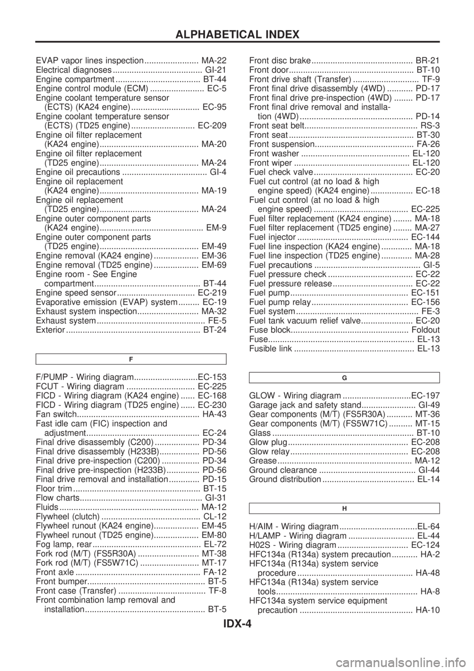
EVAP vapor lines inspection ....................... MA-22
Electrical diagnoses ...................................... GI-21
Engine compartment .................................... BT-44
Engine control module (ECM) ....................... EC-5
Engine coolant temperature sensor
(ECTS) (KA24 engine) ............................. EC-95
Engine coolant temperature sensor
(ECTS) (TD25 engine) ........................... EC-209
Engine oil filter replacement
(KA24 engine).......................................... MA-20
Engine oil filter replacement
(TD25 engine).......................................... MA-24
Engine oil precautions .................................... GI-4
Engine oil replacement
(KA24 engine).......................................... MA-19
Engine oil replacement
(TD25 engine).......................................... MA-24
Engine outer component parts
(KA24 engine)............................................ EM-9
Engine outer component parts
(TD25 engine).......................................... EM-49
Engine removal (KA24 engine) ................... EM-36
Engine removal (TD25 engine) ................... EM-69
Engine room - See Engine
compartment............................................. BT-44
Engine speed sensor ................................. EC-219
Evaporative emission (EVAP) system ......... EC-19
Exhaust system inspection.......................... MA-32
Exhaust system .............................................. FE-5
Exterior ......................................................... BT-24
F
F/PUMP - Wiring diagram...........................EC-153
FCUT - Wiring diagram ............................. EC-225
FICD - Wiring diagram (KA24 engine) ...... EC-168
FICD - Wiring diagram (TD25 engine) ...... EC-230
Fan switch.................................................... HA-43
Fast idle cam (FIC) inspection and
adjustment................................................ EC-24
Final drive disassembly (C200) ................... PD-34
Final drive disassembly (H233B)................. PD-56
Final drive pre-inspection (C200) ................ PD-34
Final drive pre-inspection (H233B) .............. PD-56
Final drive removal and installation ............. PD-15
Floor trim ...................................................... BT-15
Flow charts.................................................... GI-31
Fluids ........................................................... MA-12
Flywheel (clutch) .......................................... CL-12
Flywheel runout (KA24 engine)................... EM-45
Flywheel runout (TD25 engine)................... EM-80
Fog lamp, rear .............................................. EL-72
Fork rod (M/T) (FS5R30A) .......................... MT-38
Fork rod (M/T) (FS5W71C) ......................... MT-17
Front axle ..................................................... FA-12
Front bumper.................................................. BT-5
Front case (Transfer) ..................................... TF-8
Front combination lamp removal and
installation................................................... BT-5Front disc brake ........................................... BR-21
Front door..................................................... BT-10
Front drive shaft (Transfer) ............................ TF-9
Front final drive disassembly (4WD) ........... PD-17
Front final drive pre-inspection (4WD) ........ PD-17
Front final drive removal and installa-
tion (4WD) ................................................ PD-14
Front seat belt................................................ RS-3
Front seat ..................................................... BT-30
Front suspension.......................................... FA-26
Front washer .............................................. EL-120
Front wiper ................................................. EL-120
Fuel check valve .......................................... EC-20
Fuel cut control (at no load & high
engine speed) (KA24 engine) .................. EC-18
Fuel cut control (at no load & high
engine speed) ........................................ EC-225
Fuel filter replacement (KA24 engine) ........ MA-18
Fuel filter replacement (TD25 engine) ........ MA-27
Fuel injector ............................................... EC-144
Fuel line inspection (KA24 engine) ............. MA-18
Fuel line inspection (TD25 engine) ............. MA-28
Fuel precautions ............................................. GI-5
Fuel pressure check .................................... EC-22
Fuel pressure release .................................. EC-22
Fuel pump .................................................. EC-151
Fuel pump relay ......................................... EC-156
Fuel system .................................................... FE-3
Fuel tank vacuum relief valve...................... EC-20
Fuse block.................................................. Foldout
Fuse.............................................................. EL-13
Fusible link ................................................... EL-13G
GLOW - Wiring diagram .............................EC-197
Garage jack and safety stand....................... GI-49
Gear components (M/T) (FS5R30A) ........... MT-36
Gear components (M/T) (FS5W71C) .......... MT-15
Glass ............................................................ BT-10
Glow plug ................................................... EC-208
Glow relay .................................................. EC-208
Grease ......................................................... MA-12
Ground clearance ......................................... GI-44
Ground distribution ....................................... EL-14
H
H/AIM - Wiring diagram .................................EL-64
H/LAMP - Wiring diagram ............................ EL-44
H02S - Wiring diagram .............................. EC-124
HFC134a (R134a) system precaution ........... HA-2
HFC134a (R134a) system service
procedure ................................................. HA-48
HFC134a (R134a) system service
tools............................................................ HA-8
HFC134a system service equipment
precaution ................................................ HA-10
ALPHABETICAL INDEX
IDX-4
Page 867 of 1659
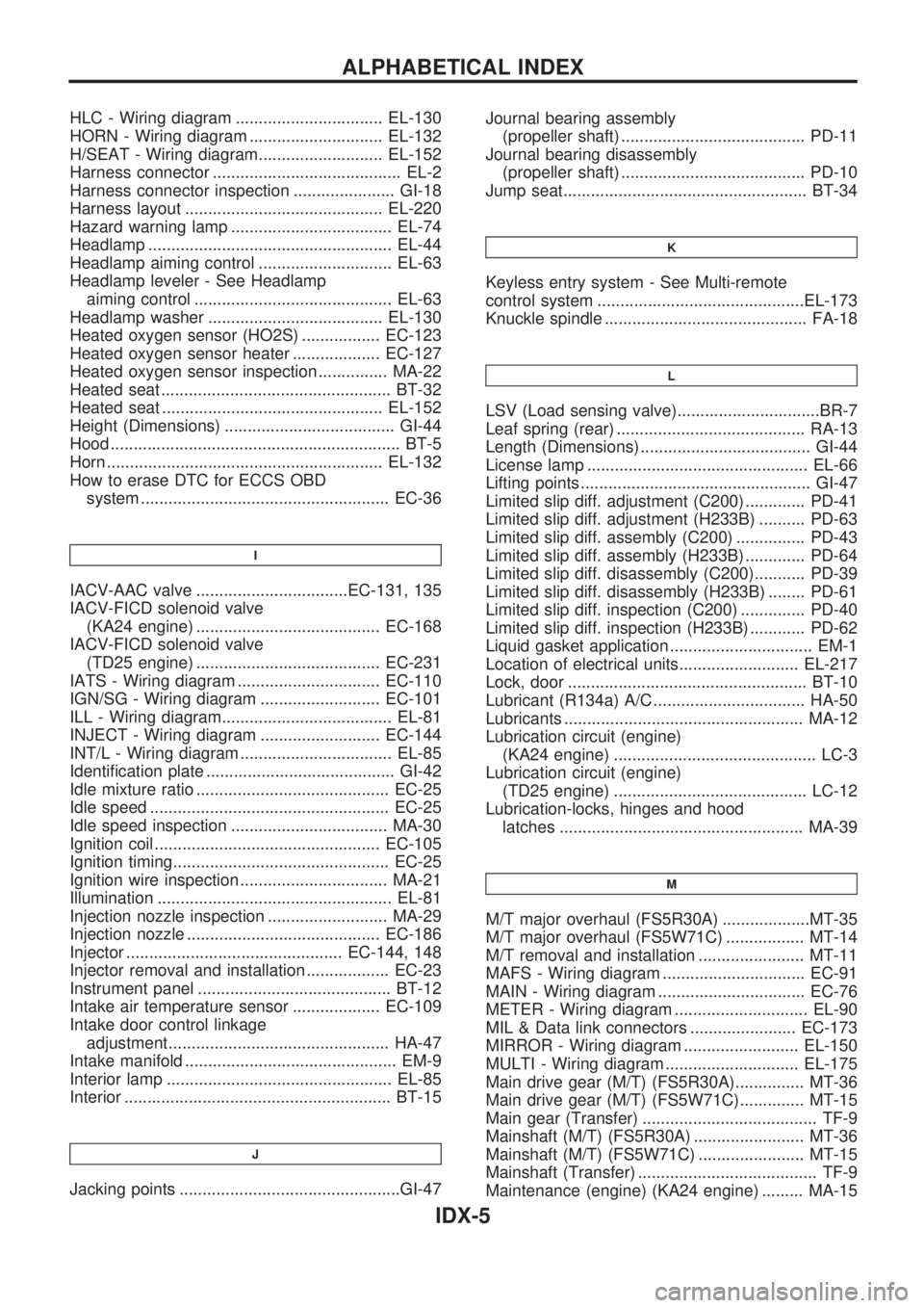
HLC - Wiring diagram ................................ EL-130
HORN - Wiring diagram ............................. EL-132
H/SEAT - Wiring diagram........................... EL-152
Harness connector ......................................... EL-2
Harness connector inspection ...................... GI-18
Harness layout ........................................... EL-220
Hazard warning lamp ................................... EL-74
Headlamp ..................................................... EL-44
Headlamp aiming control ............................. EL-63
Headlamp leveler - See Headlamp
aiming control ........................................... EL-63
Headlamp washer ...................................... EL-130
Heated oxygen sensor (HO2S) ................. EC-123
Heated oxygen sensor heater ................... EC-127
Heated oxygen sensor inspection ............... MA-22
Heated seat .................................................. BT-32
Heated seat ................................................ EL-152
Height (Dimensions) ..................................... GI-44
Hood ............................................................... BT-5
Horn ............................................................ EL-132
How to erase DTC for ECCS OBD
system ...................................................... EC-36
I
IACV-AAC valve .................................EC-131, 135
IACV-FICD solenoid valve
(KA24 engine) ........................................ EC-168
IACV-FICD solenoid valve
(TD25 engine) ........................................ EC-231
IATS - Wiring diagram ............................... EC-110
IGN/SG - Wiring diagram .......................... EC-101
ILL - Wiring diagram..................................... EL-81
INJECT - Wiring diagram .......................... EC-144
INT/L - Wiring diagram ................................. EL-85
Identification plate ......................................... GI-42
Idle mixture ratio .......................................... EC-25
Idle speed .................................................... EC-25
Idle speed inspection .................................. MA-30
Ignition coil ................................................. EC-105
Ignition timing............................................... EC-25
Ignition wire inspection ................................ MA-21
Illumination ................................................... EL-81
Injection nozzle inspection .......................... MA-29
Injection nozzle .......................................... EC-186
Injector ............................................... EC-144, 148
Injector removal and installation .................. EC-23
Instrument panel .......................................... BT-12
Intake air temperature sensor ................... EC-109
Intake door control linkage
adjustment................................................ HA-47
Intake manifold .............................................. EM-9
Interior lamp ................................................. EL-85
Interior .......................................................... BT-15
J
Jacking points ................................................GI-47Journal bearing assembly
(propeller shaft) ........................................ PD-11
Journal bearing disassembly
(propeller shaft) ........................................ PD-10
Jump seat..................................................... BT-34
K
Keyless entry system - See Multi-remote
control system .............................................EL-173
Knuckle spindle ............................................ FA-18
L
LSV (Load sensing valve)...............................BR-7
Leaf spring (rear) ......................................... RA-13
Length (Dimensions) ..................................... GI-44
License lamp ................................................ EL-66
Lifting points .................................................. GI-47
Limited slip diff. adjustment (C200) ............. PD-41
Limited slip diff. adjustment (H233B) .......... PD-63
Limited slip diff. assembly (C200) ............... PD-43
Limited slip diff. assembly (H233B) ............. PD-64
Limited slip diff. disassembly (C200)........... PD-39
Limited slip diff. disassembly (H233B) ........ PD-61
Limited slip diff. inspection (C200) .............. PD-40
Limited slip diff. inspection (H233B) ............ PD-62
Liquid gasket application ............................... EM-1
Location of electrical units.......................... EL-217
Lock, door .................................................... BT-10
Lubricant (R134a) A/C ................................. HA-50
Lubricants .................................................... MA-12
Lubrication circuit (engine)
(KA24 engine) ............................................ LC-3
Lubrication circuit (engine)
(TD25 engine) .......................................... LC-12
Lubrication-locks, hinges and hood
latches ..................................................... MA-39
M
M/T major overhaul (FS5R30A) ...................MT-35
M/T major overhaul (FS5W71C) ................. MT-14
M/T removal and installation ....................... MT-11
MAFS - Wiring diagram ............................... EC-91
MAIN - Wiring diagram ................................ EC-76
METER - Wiring diagram ............................. EL-90
MIL & Data link connectors ....................... EC-173
MIRROR - Wiring diagram ......................... EL-150
MULTI - Wiring diagram ............................. EL-175
Main drive gear (M/T) (FS5R30A)............... MT-36
Main drive gear (M/T) (FS5W71C).............. MT-15
Main gear (Transfer) ...................................... TF-9
Mainshaft (M/T) (FS5R30A) ........................ MT-36
Mainshaft (M/T) (FS5W71C) ....................... MT-15
Mainshaft (Transfer) ....................................... TF-9
Maintenance (engine) (KA24 engine) ......... MA-15
ALPHABETICAL INDEX
IDX-5
Page 995 of 1659
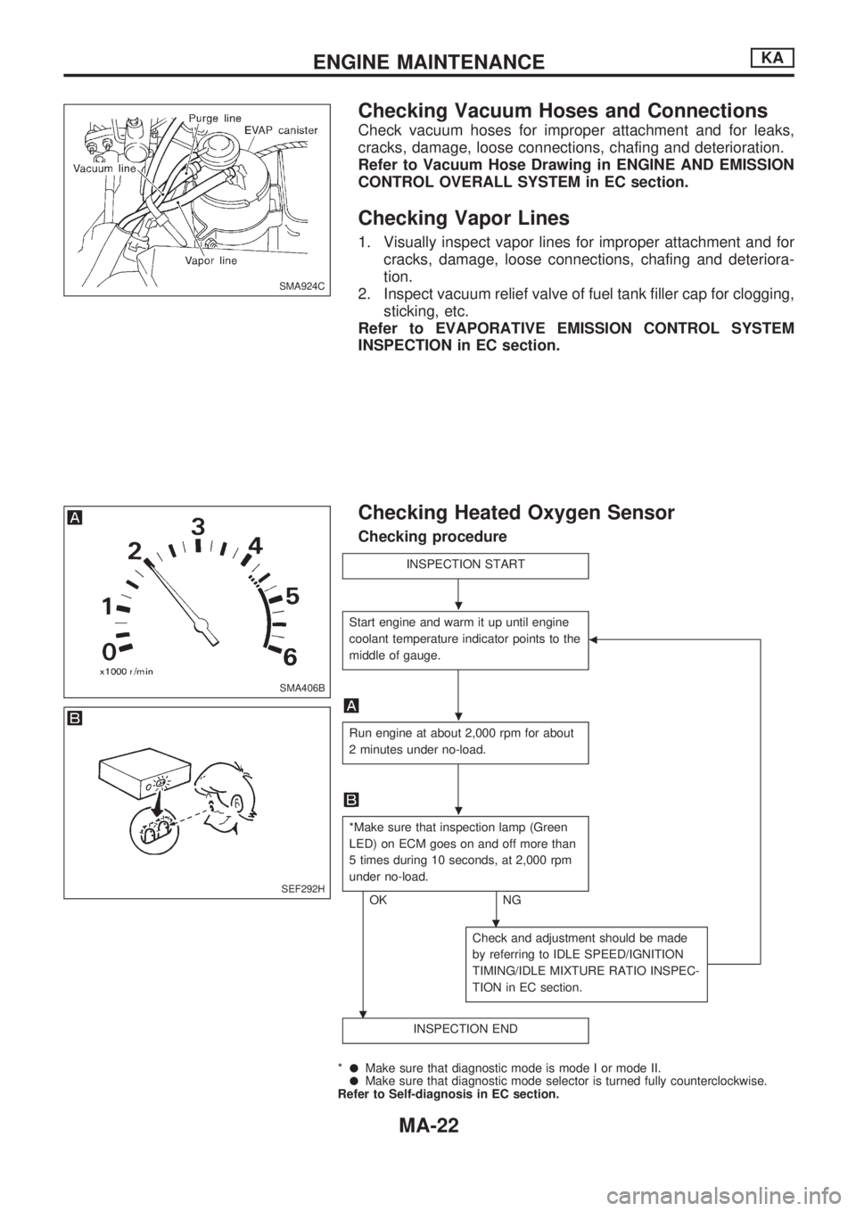
Checking Vacuum Hoses and Connections
Check vacuum hoses for improper attachment and for leaks,
cracks, damage, loose connections, chafing and deterioration.
Refer to Vacuum Hose Drawing in ENGINE AND EMISSION
CONTROL OVERALL SYSTEM in EC section.
Checking Vapor Lines
1. Visually inspect vapor lines for improper attachment and for
cracks, damage, loose connections, chafing and deteriora-
tion.
2. Inspect vacuum relief valve of fuel tank filler cap for clogging,
sticking, etc.
Refer to EVAPORATIVE EMISSION CONTROL SYSTEM
INSPECTION in EC section.
Checking Heated Oxygen Sensor
Checking procedure
INSPECTION START
Start engine and warm it up until engine
coolant temperature indicator points to the
middle of gauge.
b
Run engine at about 2,000 rpm for about
2 minutes under no-load.
*Make sure that inspection lamp (Green
LED) on ECM goes on and off more than
5 times during 10 seconds, at 2,000 rpm
under no-load.
OK NG
.
.
Check and adjustment should be made
by referring to IDLE SPEED/IGNITION
TIMING/IDLE MIXTURE RATIO INSPEC-
TION in EC section.
INSPECTION END
*lMake sure that diagnostic mode is mode I or mode II.lMake sure that diagnostic mode selector is turned fully counterclockwise.
Refer to Self-diagnosis in EC section.
SMA924C
SMA406B
SEF292H
.
.
.
ENGINE MAINTENANCEKA
MA-22
Page 1315 of 1659
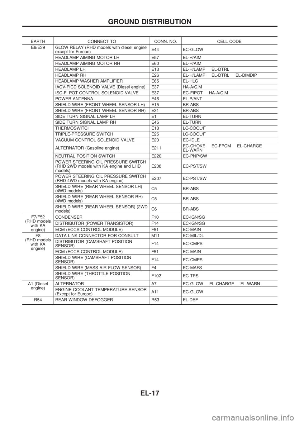
EARTH CONNECT TO CONN. NO. CELL CODE
E6/E39 GLOW RELAY (RHD models with diesel engine
except for Europe)E44 EC-GLOW
HEADLAMP AIMING MOTOR LH E57 EL-H/AIM
HEADLAMP AIMING MOTOR RH E60 EL-H/AIM
HEADLAMP LH E13 EL-H/LAMP EL-DTRL
HEADLAMP RH E26 EL-H/LAMP EL-DTRL EL-DIMDIP
HEADLAMP WASHER AMPLIFIER E65 EL-HLC
IACV-FICD SOLENOID VALVE (Diesel engine) E37 HA-A/C,M
ISC-FI POT CONTROL SOLENOID VALVE E37 EC-FIPOT HA-A/C,M
POWER ANTENNA E46 EL-P/ANT
SHIELD WIRE (FRONT WHEEL SENSOR LH) E15 BR-ABS
SHIELD WIRE (FRONT WHEEL SENSOR RH) E31 BR-ABS
SIDE TURN SIGNAL LAMP LH E1 EL-TURN
SIDE TURN SIGNAL LAMP RH E45 EL-TURN
THERMOSWITCH E18 LC-COOL/F
TRIPLE-PRESSURE SWITCH E25 LC-COOL/F
VACUUM CONTROL SOLENOID VALVE E20 EC-IDLE
ALTERNATOR (Gasoline engine) E211EC-CHOKE EC-FPCM EL-CHARGE
EL-WARN
NEUTRAL POSITION SWITCH E220 EC-PNP/SW
POWER STEERING OIL PRESSURE SWITCH
(RHD 2WD models with KA engine and LHD
models)E208 EC-PST/SW
POWER STEERING OIL PRESSURE SWITCH
(RHD 4WD models with KA engine)E207 EC-PST/SW
SHIELD WIRE (REAR WHEEL SENSOR LH)
(4WD models)C5 BR-ABS
SHIELD WIRE (REAR WHEEL SENSOR RH)
(4WD models)C5 BR-ABS
SHIELD WIRE (REAR WHEEL SENSOR) (2WD
models)C6 BR-ABS
F7/F52
(RHD models
with KA
engine)CONDENSER F10 EC-IGN/SG
DISTRIBUTOR (POWER TRANSISTOR) F14 EC-IGN/SG
ECM (ECCS CONTROL MODULE) F51 EC-MAIN
F8
(RHD models
with KA
engine)DATA LINK CONNECTOR FOR CONSULT M11 EC-MIL/DL
DISTRIBUTOR (CAMSHAFT POSITION
SENSOR)F14 EC-CMPS
ECM (ECCS CONTROL MODULE) F51 EC-MAIN
SHIELD WIRE (CAMSHAFT POSITION
SENSOR)F14 EC-CMPS
SHIELD WIRE (MASS AIR FLOW SENSOR) F4 EC-MAFS
SHIELD WIRE (THROTTLE POSITION
SENSOR)F102 EC-TPS
A1 (Diesel
engine)ALTERNATOR A7 EC-GLOW EL-CHARGE EL-WARN
ENGINE COOLANT TEMPERATURE SENSOR
(Except for Europe)A11 EC-GLOW
R54 REAR WINDOW DEFOGGER R53 EL-DEF
GROUND DISTRIBUTION
EL-17
Page 1402 of 1659
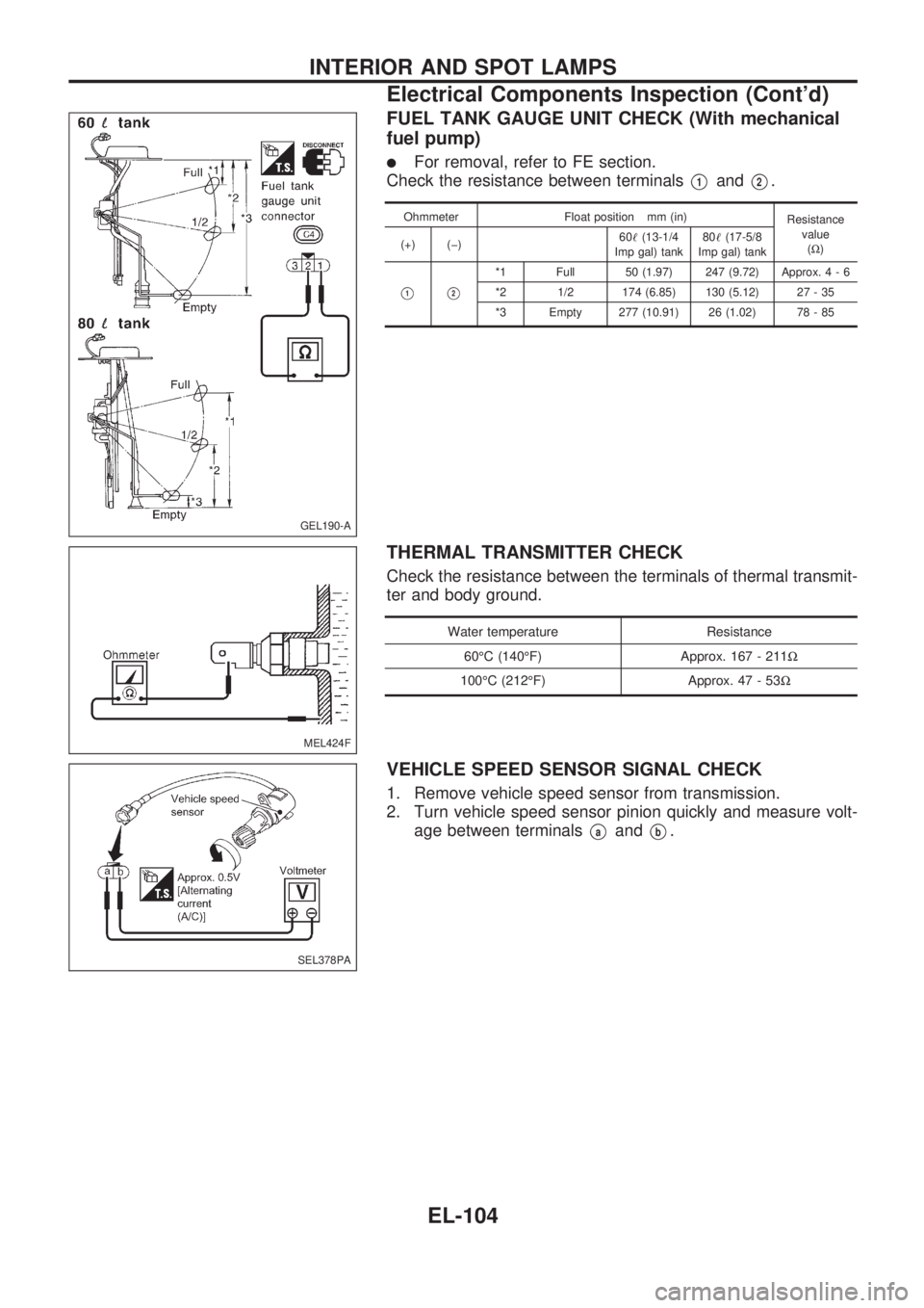
FUEL TANK GAUGE UNIT CHECK (With mechanical
fuel pump)
lFor removal, refer to FE section.
Check the resistance between terminals
V1andV2.
Ohmmeter Float position mm (in)
Resistance
value
(W) (+) (þ)60!(13-1/4
Imp gal) tank80!(17-5/8
Imp gal) tank
V1V2
*1 Full 50 (1.97) 247 (9.72) Approx. 4 - 6
*2 1/2 174 (6.85) 130 (5.12) 27 - 35
*3 Empty 277 (10.91) 26 (1.02) 78 - 85
THERMAL TRANSMITTER CHECK
Check the resistance between the terminals of thermal transmit-
ter and body ground.
Water temperature Resistance
60ÉC (140ÉF) Approx. 167 - 211W
100ÉC (212ÉF) Approx. 47 - 53W
VEHICLE SPEED SENSOR SIGNAL CHECK
1. Remove vehicle speed sensor from transmission.
2. Turn vehicle speed sensor pinion quickly and measure volt-
age between terminals
VaandVb.
GEL190-A
MEL424F
SEL378PA
INTERIOR AND SPOT LAMPS
Electrical Components Inspection (Cont'd)
EL-104