temperature sensor NISSAN PICK-UP 1998 Owner's Manual
[x] Cancel search | Manufacturer: NISSAN, Model Year: 1998, Model line: PICK-UP, Model: NISSAN PICK-UP 1998Pages: 1659, PDF Size: 53.39 MB
Page 241 of 1659
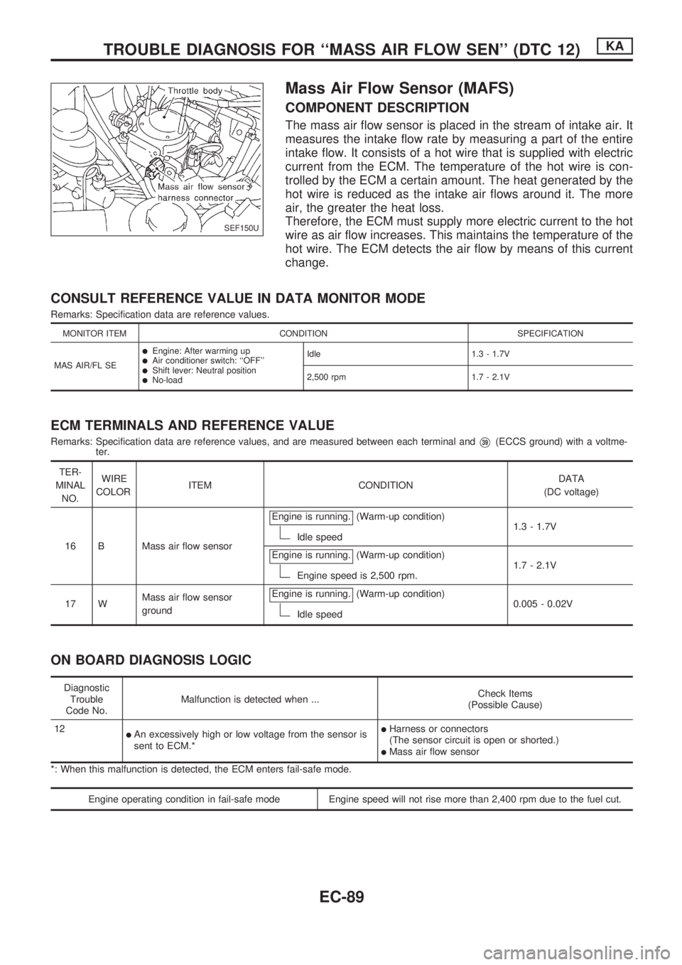
Mass Air Flow Sensor (MAFS)
COMPONENT DESCRIPTION
The mass air flow sensor is placed in the stream of intake air. It
measures the intake flow rate by measuring a part of the entire
intake flow. It consists of a hot wire that is supplied with electric
current from the ECM. The temperature of the hot wire is con-
trolled by the ECM a certain amount. The heat generated by the
hot wire is reduced as the intake air flows around it. The more
air, the greater the heat loss.
Therefore, the ECM must supply more electric current to the hot
wire as air flow increases. This maintains the temperature of the
hot wire. The ECM detects the air flow by means of this current
change.
CONSULT REFERENCE VALUE IN DATA MONITOR MODE
Remarks: Specification data are reference values.
MONITOR ITEM CONDITION SPECIFICATION
MAS AIR/FL SE
lEngine: After warming uplAir conditioner switch: ``OFF''lShift lever: Neutral positionlNo-loadIdle 1.3 - 1.7V
2,500 rpm 1.7 - 2.1V
ECM TERMINALS AND REFERENCE VALUE
Remarks: Specification data are reference values, and are measured between each terminal andV39(ECCS ground) with a voltme-
ter.
TER-
MINAL
NO.WIRE
COLORITEM CONDITIONDATA
(DC voltage)
16 B Mass air flow sensorEngine is running.
(Warm-up condition)
Idle speed1.3 - 1.7V
Engine is running.
(Warm-up condition)
Engine speed is 2,500 rpm.1.7 - 2.1V
17 WMass air flow sensor
groundEngine is running.
(Warm-up condition)
Idle speed0.005 - 0.02V
ON BOARD DIAGNOSIS LOGIC
Diagnostic
Trouble
Code No.Malfunction is detected when ...Check Items
(Possible Cause)
12
lAn excessively high or low voltage from the sensor is
sent to ECM.*lHarness or connectors
(The sensor circuit is open or shorted.)
lMass air flow sensor
*: When this malfunction is detected, the ECM enters fail-safe mode.
Engine operating condition in fail-safe mode Engine speed will not rise more than 2,400 rpm due to the fuel cut.
SEF150U
TROUBLE DIAGNOSIS FOR ``MASS AIR FLOW SEN'' (DTC 12)KA
EC-89
Page 247 of 1659
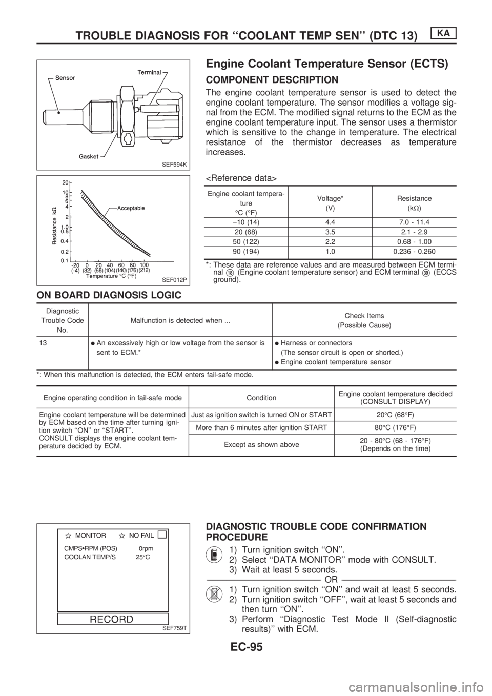
Engine Coolant Temperature Sensor (ECTS)
COMPONENT DESCRIPTION
The engine coolant temperature sensor is used to detect the
engine coolant temperature. The sensor modifies a voltage sig-
nal from the ECM. The modified signal returns to the ECM as the
engine coolant temperature input. The sensor uses a thermistor
which is sensitive to the change in temperature. The electrical
resistance of the thermistor decreases as temperature
increases.
Engine coolant tempera-
ture
ÉC (ÉF)Voltage*
(V)Resistance
(kW)
þ10 (14) 4.4 7.0 - 11.4
20 (68) 3.5 2.1 - 2.9
50 (122) 2.2 0.68 - 1.00
90 (194) 1.0 0.236 - 0.260
*: These data are reference values and are measured between ECM termi-
nal
V18(Engine coolant temperature sensor) and ECM terminalV39(ECCS
ground).
ON BOARD DIAGNOSIS LOGIC
Diagnostic
Trouble Code
No.Malfunction is detected when ...Check Items
(Possible Cause)
13
lAn excessively high or low voltage from the sensor is
sent to ECM.*lHarness or connectors
(The sensor circuit is open or shorted.)
lEngine coolant temperature sensor
*: When this malfunction is detected, the ECM enters fail-safe mode.
Engine operating condition in fail-safe mode ConditionEngine coolant temperature decided
(CONSULT DISPLAY)
Engine coolant temperature will be determined
by ECM based on the time after turning igni-
tion switch ``ON'' or ``START''.
CONSULT displays the engine coolant tem-
perature decided by ECM.Just as ignition switch is turned ON or START 20ÉC (68ÉF)
More than 6 minutes after ignition START 80ÉC (176ÉF)
Except as shown above20 - 80ÉC (68 - 176ÉF)
(Depends on the time)
DIAGNOSTIC TROUBLE CODE CONFIRMATION
PROCEDURE
1) Turn ignition switch ``ON''.
2) Select ``DATA MONITOR'' mode with CONSULT.
3) Wait at least 5 seconds.
-------------------------------------------------------------------------------------------------------------------------------------------------------------------------------------------------------------------------------------------------OR-------------------------------------------------------------------------------------------------------------------------------------------------------------------------------------------------------------------------------------------------
1) Turn ignition switch ``ON'' and wait at least 5 seconds.
2) Turn ignition switch ``OFF'', wait at least 5 seconds and
then turn ``ON''.
3) Perform ``Diagnostic Test Mode II (Self-diagnostic
results)'' with ECM.
SEF594K
SEF012P
SEF759T
TROUBLE DIAGNOSIS FOR ``COOLANT TEMP SEN'' (DTC 13)KA
EC-95
Page 248 of 1659
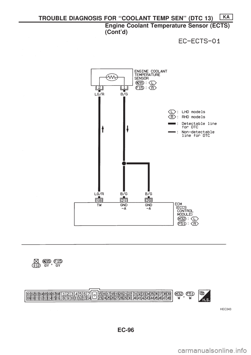
HEC343
TROUBLE DIAGNOSIS FOR ``COOLANT TEMP SEN'' (DTC 13)KA
Engine Coolant Temperature Sensor (ECTS)
(Cont'd)
EC-96
Page 249 of 1659
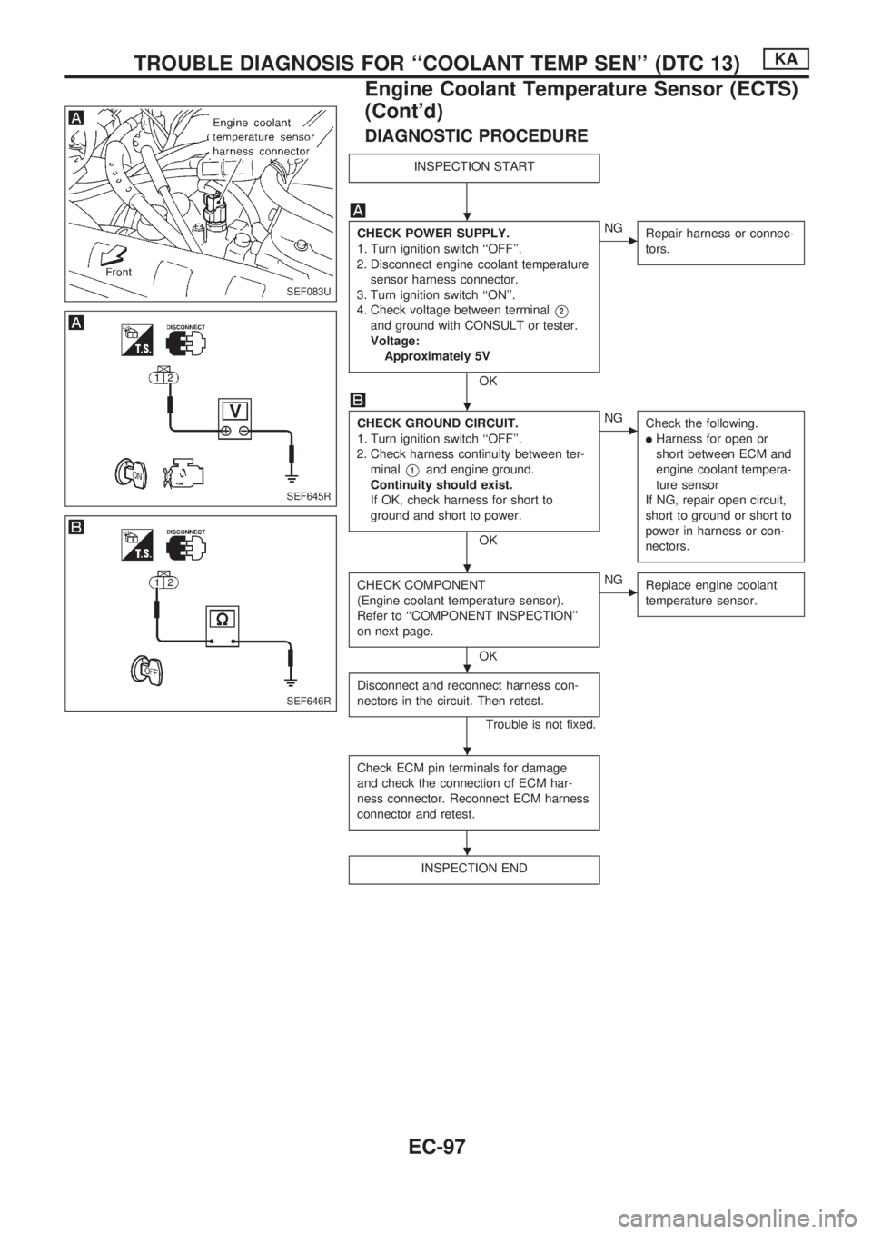
DIAGNOSTIC PROCEDURE
INSPECTION START
CHECK POWER SUPPLY.
1. Turn ignition switch ``OFF''.
2. Disconnect engine coolant temperature
sensor harness connector.
3. Turn ignition switch ``ON''.
4. Check voltage between terminal
V2
and ground with CONSULT or tester.
Voltage:
Approximately 5V
OK
cNG
Repair harness or connec-
tors.
CHECK GROUND CIRCUIT.
1. Turn ignition switch ``OFF''.
2. Check harness continuity between ter-
minal
V1and engine ground.
Continuity should exist.
If OK, check harness for short to
ground and short to power.
OK
cNG
Check the following.
lHarness for open or
short between ECM and
engine coolant tempera-
ture sensor
If NG, repair open circuit,
short to ground or short to
power in harness or con-
nectors.
CHECK COMPONENT
(Engine coolant temperature sensor).
Refer to ``COMPONENT INSPECTION''
on next page.
OK
cNG
Replace engine coolant
temperature sensor.
Disconnect and reconnect harness con-
nectors in the circuit. Then retest.
Trouble is not fixed.
Check ECM pin terminals for damage
and check the connection of ECM har-
ness connector. Reconnect ECM harness
connector and retest.
INSPECTION END
SEF083U
SEF645R
SEF646R
.
.
.
.
.
.
TROUBLE DIAGNOSIS FOR ``COOLANT TEMP SEN'' (DTC 13)KA
Engine Coolant Temperature Sensor (ECTS)
(Cont'd)
EC-97
Page 250 of 1659
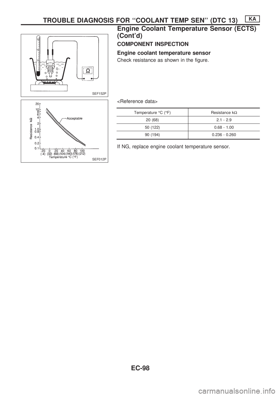
COMPONENT INSPECTION
Engine coolant temperature sensor
Check resistance as shown in the figure.
Temperature ÉC (ÉF) Resistance kW
20 (68) 2.1 - 2.9
50 (122) 0.68 - 1.00
90 (194) 0.236 - 0.260
If NG, replace engine coolant temperature sensor.
SEF152P
SEF012P
TROUBLE DIAGNOSIS FOR ``COOLANT TEMP SEN'' (DTC 13)KA
Engine Coolant Temperature Sensor (ECTS)
(Cont'd)
EC-98
Page 259 of 1659
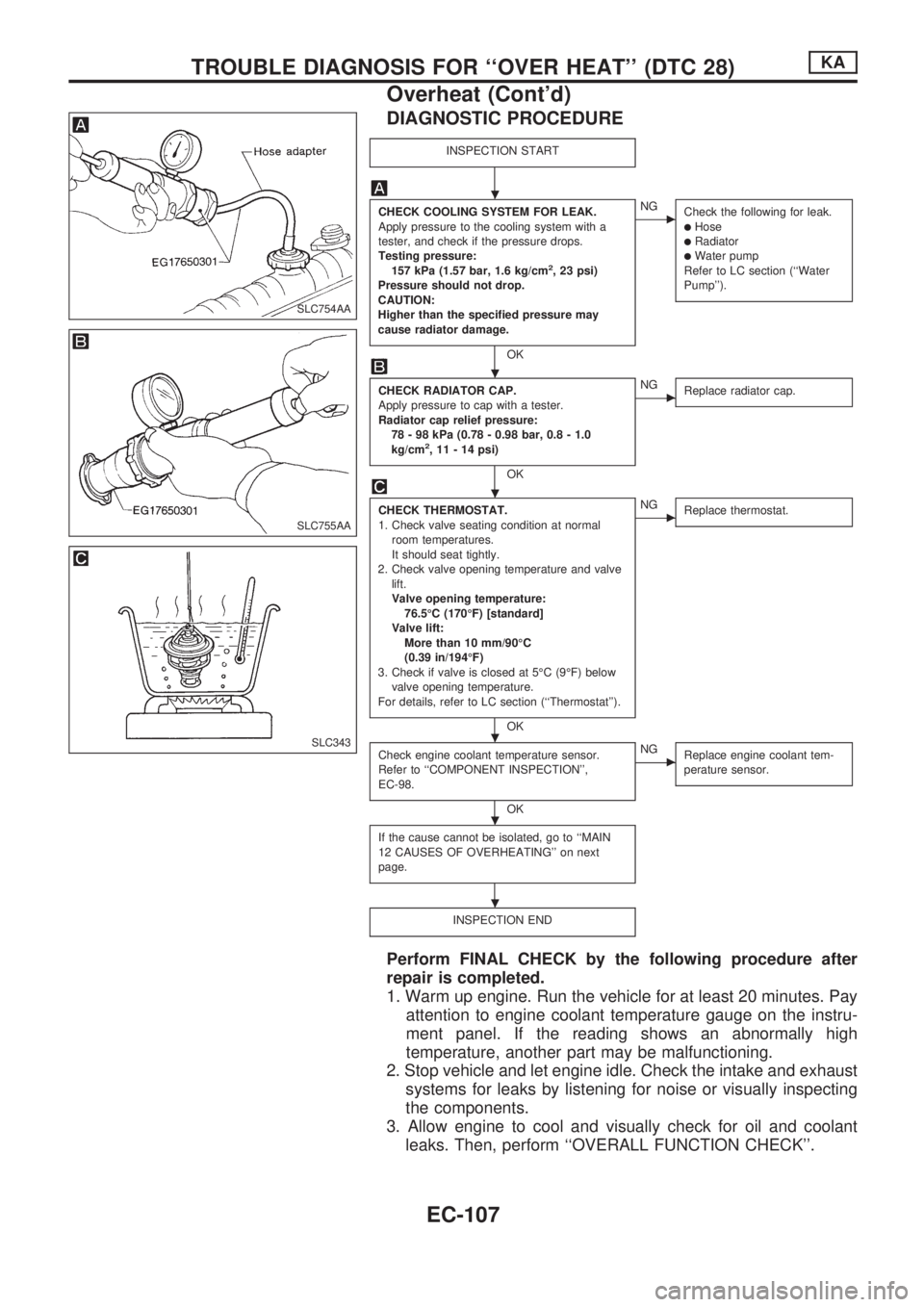
DIAGNOSTIC PROCEDURE
INSPECTION START
CHECK COOLING SYSTEM FOR LEAK.
Apply pressure to the cooling system with a
tester, and check if the pressure drops.
Testing pressure:
157 kPa (1.57 bar, 1.6 kg/cm
2, 23 psi)
Pressure should not drop.
CAUTION:
Higher than the specified pressure may
cause radiator damage.
OK
cNG
Check the following for leak.
lHoselRadiatorlWater pump
Refer to LC section (``Water
Pump'').
CHECK RADIATOR CAP.
Apply pressure to cap with a tester.
Radiator cap relief pressure:
78 - 98 kPa (0.78 - 0.98 bar, 0.8 - 1.0
kg/cm
2, 11 - 14 psi)
OK
cNG
Replace radiator cap.
CHECK THERMOSTAT.
1. Check valve seating condition at normal
room temperatures.
It should seat tightly.
2. Check valve opening temperature and valve
lift.
Valve opening temperature:
76.5ÉC (170ÉF) [standard]
Valve lift:
More than 10 mm/90ÉC
(0.39 in/194ÉF)
3. Check if valve is closed at 5ÉC (9ÉF) below
valve opening temperature.
For details, refer to LC section (``Thermostat'').
OK
cNG
Replace thermostat.
Check engine coolant temperature sensor.
Refer to ``COMPONENT INSPECTION'',
EC-98.
OK
cNG
Replace engine coolant tem-
perature sensor.
If the cause cannot be isolated, go to ``MAIN
12 CAUSES OF OVERHEATING'' on next
page.
INSPECTION END
Perform FINAL CHECK by the following procedure after
repair is completed.
1. Warm up engine. Run the vehicle for at least 20 minutes. Pay
attention to engine coolant temperature gauge on the instru-
ment panel. If the reading shows an abnormally high
temperature, another part may be malfunctioning.
2. Stop vehicle and let engine idle. Check the intake and exhaust
systems for leaks by listening for noise or visually inspecting
the components.
3. Allow engine to cool and visually check for oil and coolant
leaks. Then, perform ``OVERALL FUNCTION CHECK''.
SLC754AA
SLC755AA
SLC343
.
.
.
.
.
.
TROUBLE DIAGNOSIS FOR ``OVER HEAT'' (DTC 28)KA
Overheat (Cont'd)
EC-107
Page 261 of 1659
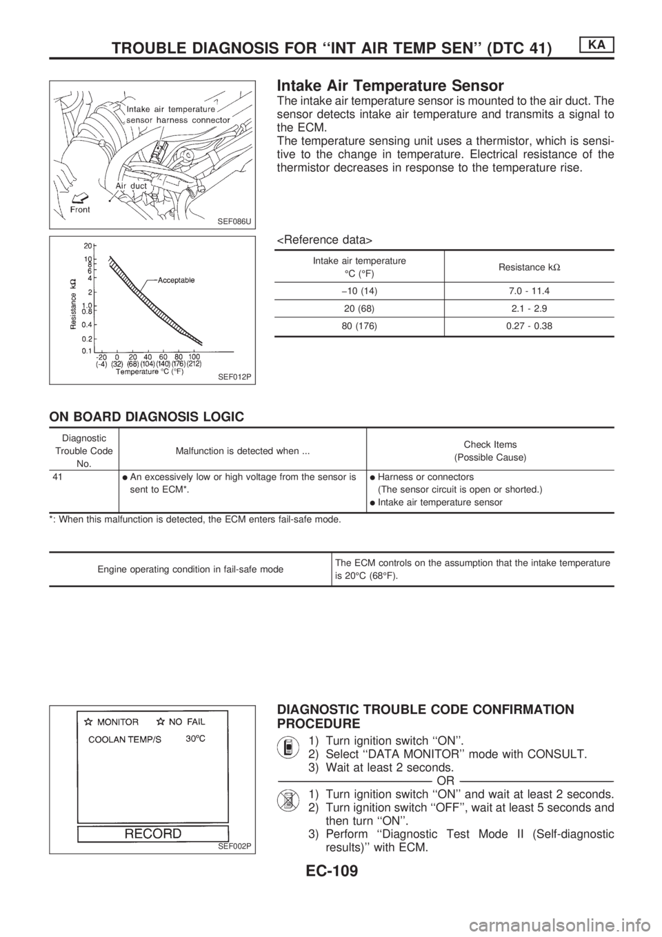
Intake Air Temperature Sensor
The intake air temperature sensor is mounted to the air duct. The
sensor detects intake air temperature and transmits a signal to
the ECM.
The temperature sensing unit uses a thermistor, which is sensi-
tive to the change in temperature. Electrical resistance of the
thermistor decreases in response to the temperature rise.
Intake air temperature
ÉC (ÉF)Resistance kW
þ10 (14) 7.0 - 11.4
20 (68) 2.1 - 2.9
80 (176) 0.27 - 0.38
ON BOARD DIAGNOSIS LOGIC
Diagnostic
Trouble Code
No.Malfunction is detected when ...Check Items
(Possible Cause)
41
lAn excessively low or high voltage from the sensor is
sent to ECM*.lHarness or connectors
(The sensor circuit is open or shorted.)
lIntake air temperature sensor
*: When this malfunction is detected, the ECM enters fail-safe mode.
Engine operating condition in fail-safe modeThe ECM controls on the assumption that the intake temperature
is 20ÉC (68ÉF).
DIAGNOSTIC TROUBLE CODE CONFIRMATION
PROCEDURE
1) Turn ignition switch ``ON''.
2) Select ``DATA MONITOR'' mode with CONSULT.
3) Wait at least 2 seconds.
-------------------------------------------------------------------------------------------------------------------------------------------------------------------------------------------------------------------------------------------------OR-------------------------------------------------------------------------------------------------------------------------------------------------------------------------------------------------------------------------------------------------
1) Turn ignition switch ``ON'' and wait at least 2 seconds.
2) Turn ignition switch ``OFF'', wait at least 5 seconds and
then turn ``ON''.
3) Perform ``Diagnostic Test Mode II (Self-diagnostic
results)'' with ECM.
SEF086U
SEF012P
SEF002P
TROUBLE DIAGNOSIS FOR ``INT AIR TEMP SEN'' (DTC 41)KA
EC-109
Page 262 of 1659
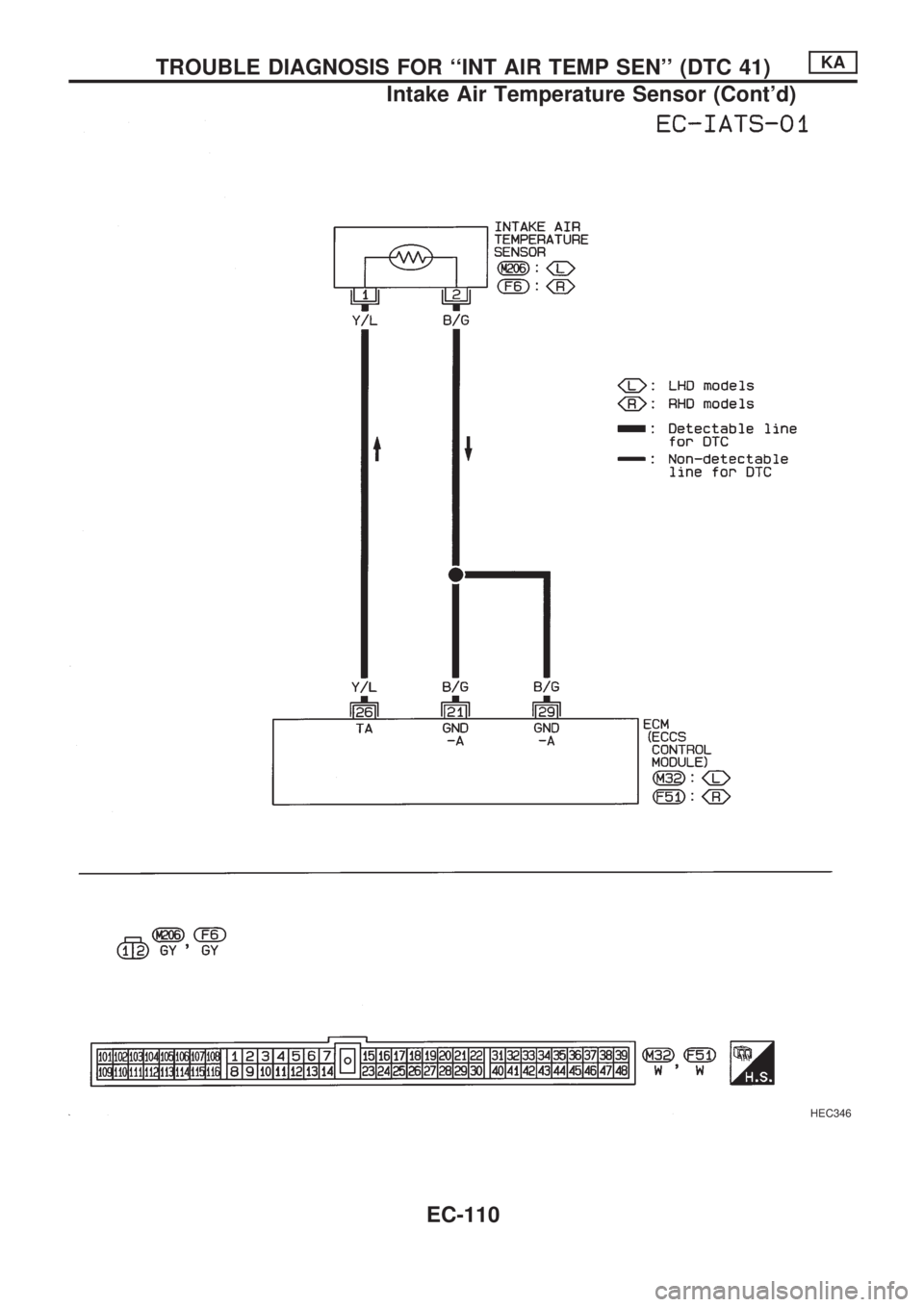
HEC346
TROUBLE DIAGNOSIS FOR ``INT AIR TEMP SEN'' (DTC 41)KA
Intake Air Temperature Sensor (Cont'd)
EC-110
Page 263 of 1659
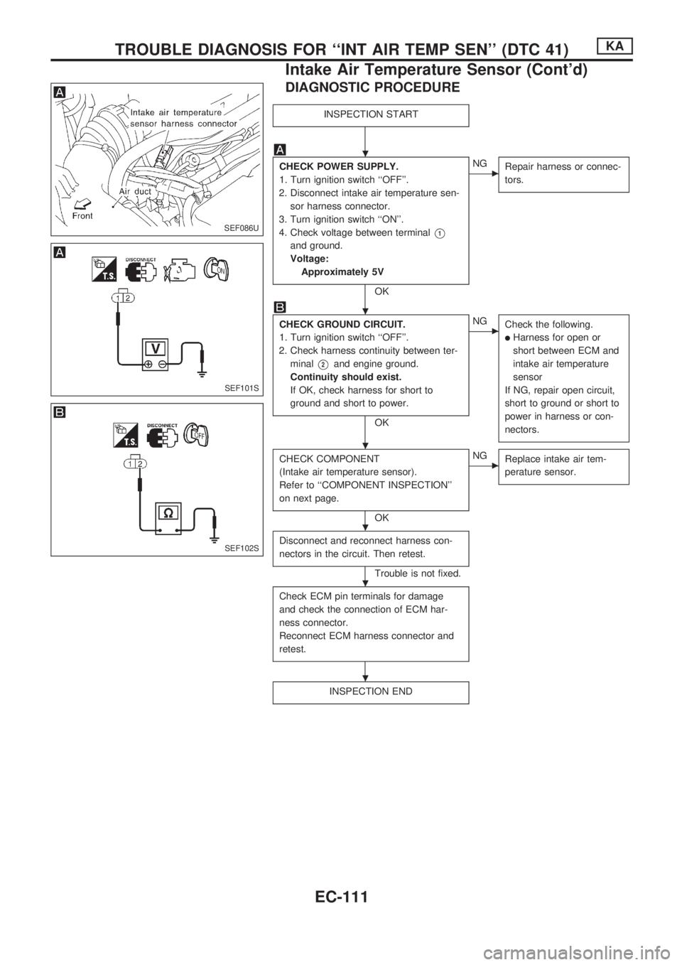
DIAGNOSTIC PROCEDURE
INSPECTION START
CHECK POWER SUPPLY.
1. Turn ignition switch ``OFF''.
2. Disconnect intake air temperature sen-
sor harness connector.
3. Turn ignition switch ``ON''.
4. Check voltage between terminal
V1
and ground.
Voltage:
Approximately 5V
OK
cNG
Repair harness or connec-
tors.
CHECK GROUND CIRCUIT.
1. Turn ignition switch ``OFF''.
2. Check harness continuity between ter-
minal
V2and engine ground.
Continuity should exist.
If OK, check harness for short to
ground and short to power.
OK
cNG
Check the following.
lHarness for open or
short between ECM and
intake air temperature
sensor
If NG, repair open circuit,
short to ground or short to
power in harness or con-
nectors.
CHECK COMPONENT
(Intake air temperature sensor).
Refer to ``COMPONENT INSPECTION''
on next page.
OK
cNG
Replace intake air tem-
perature sensor.
Disconnect and reconnect harness con-
nectors in the circuit. Then retest.
Trouble is not fixed.
Check ECM pin terminals for damage
and check the connection of ECM har-
ness connector.
Reconnect ECM harness connector and
retest.
INSPECTION END
SEF086U
SEF101S
SEF102S
.
.
.
.
.
.
TROUBLE DIAGNOSIS FOR ``INT AIR TEMP SEN'' (DTC 41)KA
Intake Air Temperature Sensor (Cont'd)
EC-111
Page 264 of 1659
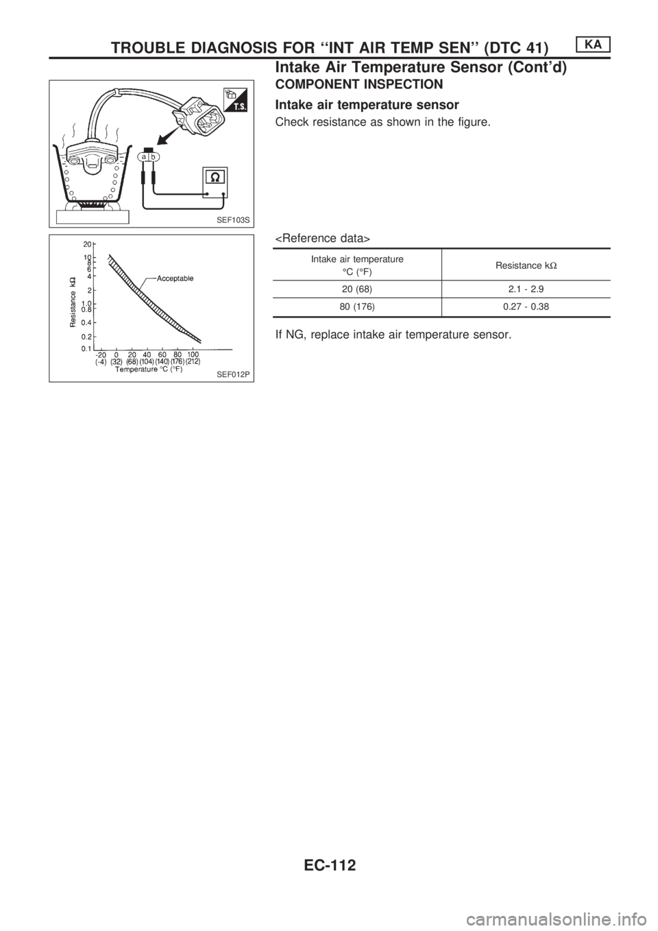
COMPONENT INSPECTION
Intake air temperature sensor
Check resistance as shown in the figure.
Intake air temperature
ÉC (ÉF)Resistance kW
20 (68) 2.1 - 2.9
80 (176) 0.27 - 0.38
If NG, replace intake air temperature sensor.
SEF103S
SEF012P
TROUBLE DIAGNOSIS FOR ``INT AIR TEMP SEN'' (DTC 41)KA
Intake Air Temperature Sensor (Cont'd)
EC-112