boot NISSAN PICK-UP 1998 Repair Manual
[x] Cancel search | Manufacturer: NISSAN, Model Year: 1998, Model line: PICK-UP, Model: NISSAN PICK-UP 1998Pages: 1659, PDF Size: 53.39 MB
Page 25 of 1659
Pad Replacement
WARNING:
Clean brake pads with a vacuum dust collector to minimize
the hazard of airborne materials.
CAUTION:
lWhen cylinder body is open, do not depress brake pedal
or caliper piston will pop out.
lBe careful not to damage piston boot or get oil on rotor.
Always replace shims when replacing pads.
lIf shims are rusted or show peeling of the rubber coat,
replace them with new shims.
lIt is not necessary to remove connecting bolt except for
disassembly or replacement of caliper assembly. In this
case, suspend cylinder body with wire so as not to
stretch brake hose.
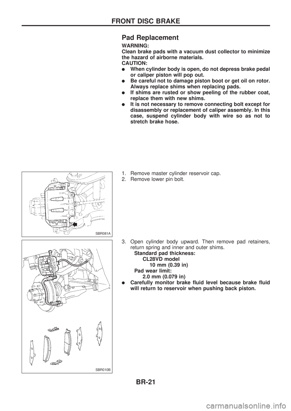
1. Remove master cylinder reservoir cap.
2. Remove lower pin bolt.
3. Open cylinder body upward. Then remove pad retainers,
return spring and inner and outer shims.
Standard pad thickness:
CL28VD model
10 mm (0.39 in)
Pad wear limit:
2.0 mm (0.079 in)
lCarefully monitor brake fluid level because brake fluid
will return to reservoir when pushing back piston.
SBR081A
SBR010B
FRONT DISC BRAKE
BR-21
Page 27 of 1659
Disassembly
WARNING:
Do not place your fingers in front of piston.
CAUTION:
lDo not scratch or score cylinder wall.
lCL28VD type front disc brake uses plastic pistons,
handle them carefully.
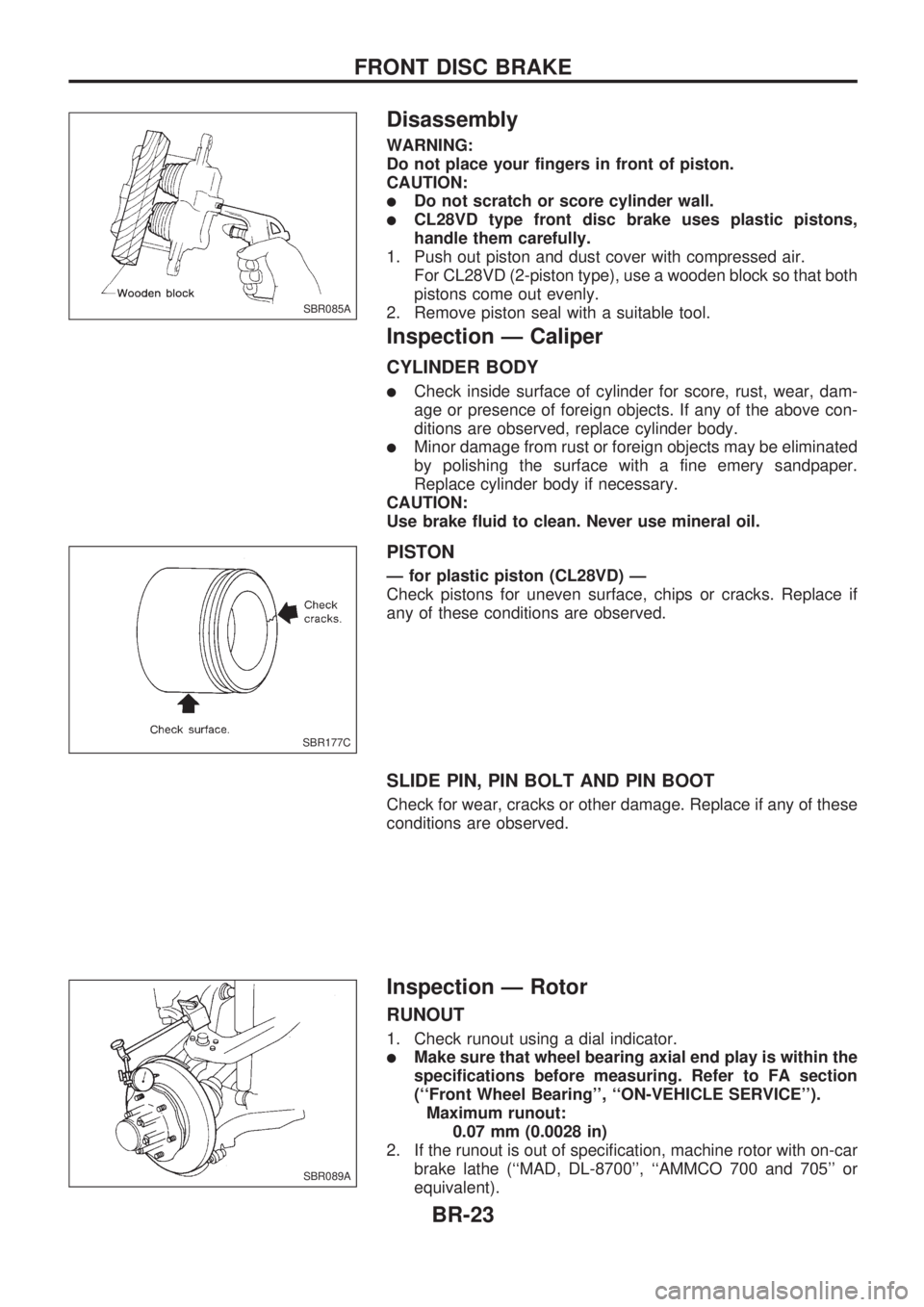
1. Push out piston and dust cover with compressed air.
For CL28VD (2-piston type), use a wooden block so that both
pistons come out evenly.
2. Remove piston seal with a suitable tool.
Inspection Ð Caliper
CYLINDER BODY
lCheck inside surface of cylinder for score, rust, wear, dam-
age or presence of foreign objects. If any of the above con-
ditions are observed, replace cylinder body.
lMinor damage from rust or foreign objects may be eliminated
by polishing the surface with a fine emery sandpaper.
Replace cylinder body if necessary.
CAUTION:
Use brake fluid to clean. Never use mineral oil.
PISTON
Ð for plastic piston (CL28VD) Ð
Check pistons for uneven surface, chips or cracks. Replace if
any of these conditions are observed.
SLIDE PIN, PIN BOLT AND PIN BOOT
Check for wear, cracks or other damage. Replace if any of these
conditions are observed.
Inspection Ð Rotor
RUNOUT
1. Check runout using a dial indicator.
lMake sure that wheel bearing axial end play is within the
specifications before measuring. Refer to FA section
(``Front Wheel Bearing'', ``ON-VEHICLE SERVICE'').
Maximum runout:
0.07 mm (0.0028 in)
2. If the runout is out of specification, machine rotor with on-car
brake lathe (``MAD, DL-8700'', ``AMMCO 700 and 705'' or
equivalent).
SBR085A
SBR177C
SBR089A
FRONT DISC BRAKE
BR-23
Page 28 of 1659
THICKNESS
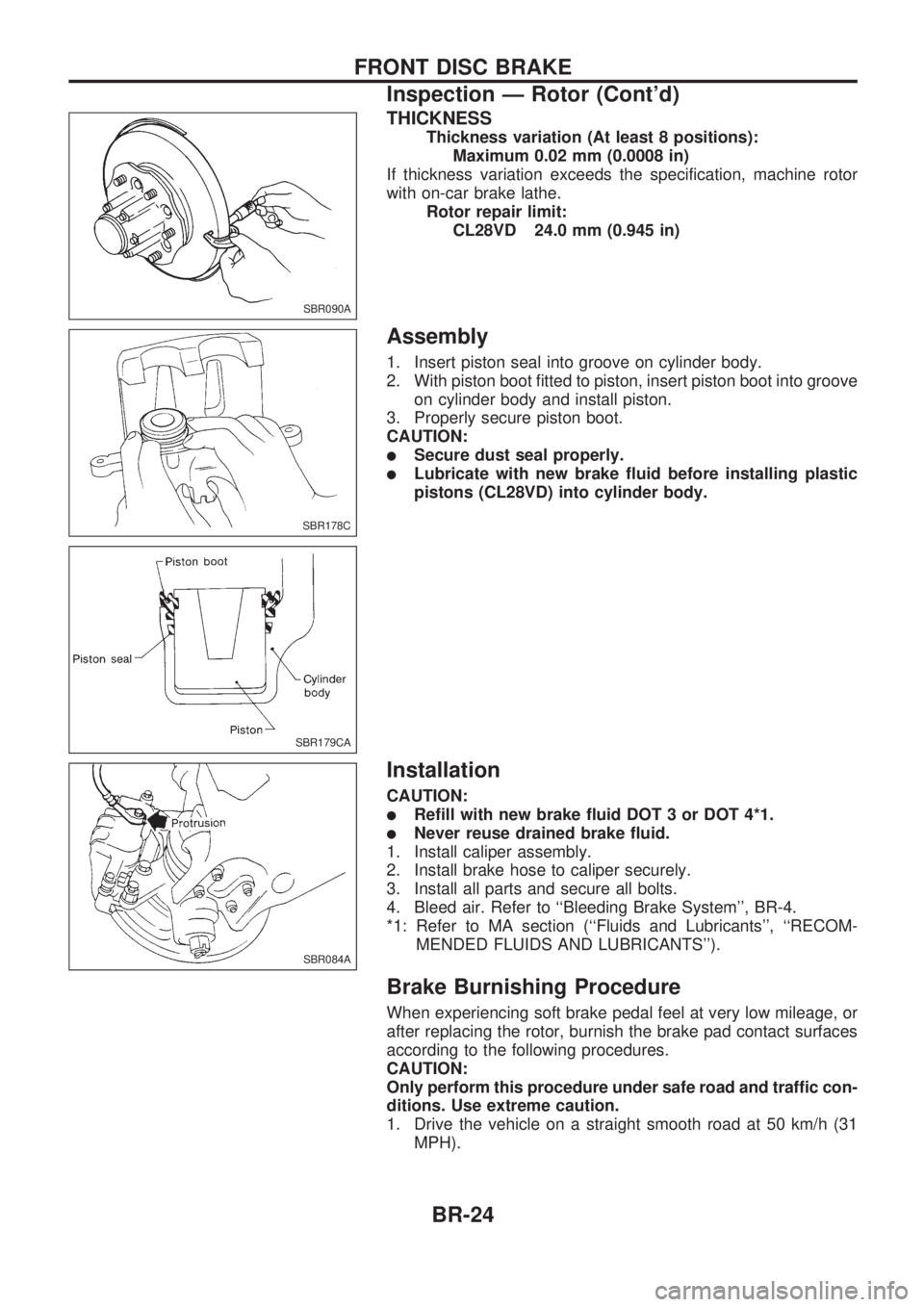
Thickness variation (At least 8 positions):
Maximum 0.02 mm (0.0008 in)
If thickness variation exceeds the specification, machine rotor
with on-car brake lathe.
Rotor repair limit:
CL28VD 24.0 mm (0.945 in)
Assembly
1. Insert piston seal into groove on cylinder body.
2. With piston boot fitted to piston, insert piston boot into groove
on cylinder body and install piston.
3. Properly secure piston boot.
CAUTION:
lSecure dust seal properly.
lLubricate with new brake fluid before installing plastic
pistons (CL28VD) into cylinder body.
Installation
CAUTION:
lRefill with new brake fluid DOT 3 or DOT 4*1.
lNever reuse drained brake fluid.
1. Install caliper assembly.
2. Install brake hose to caliper securely.
3. Install all parts and secure all bolts.
4. Bleed air. Refer to ``Bleeding Brake System'', BR-4.
*1: Refer to MA section (``Fluids and Lubricants'', ``RECOM-
MENDED FLUIDS AND LUBRICANTS'').
Brake Burnishing Procedure
When experiencing soft brake pedal feel at very low mileage, or
after replacing the rotor, burnish the brake pad contact surfaces
according to the following procedures.
CAUTION:
Only perform this procedure under safe road and traffic con-
ditions. Use extreme caution.
1. Drive the vehicle on a straight smooth road at 50 km/h (31
MPH).
SBR090A
SBR178C
SBR179CA
SBR084A
FRONT DISC BRAKE
Inspection Ð Rotor (Cont'd)
BR-24
Page 31 of 1659
Removal
WARNING:
Clean brake lining with a vacuum dust collector to minimize
the hazard of airborne materials.
CAUTION:
Make sure parking brake lever is completely released.
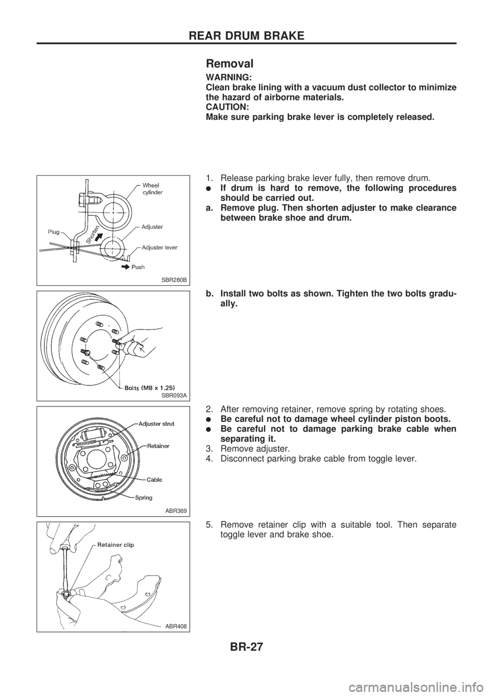
1. Release parking brake lever fully, then remove drum.
lIf drum is hard to remove, the following procedures
should be carried out.
a. Remove plug. Then shorten adjuster to make clearance
between brake shoe and drum.
b. Install two bolts as shown. Tighten the two bolts gradu-
ally.
2. After removing retainer, remove spring by rotating shoes.
lBe careful not to damage wheel cylinder piston boots.
lBe careful not to damage parking brake cable when
separating it.
3. Remove adjuster.
4. Disconnect parking brake cable from toggle lever.
5. Remove retainer clip with a suitable tool. Then separate
toggle lever and brake shoe.
SBR280B
SBR093A
ABR369
ABR408
REAR DRUM BRAKE
BR-27
Page 33 of 1659
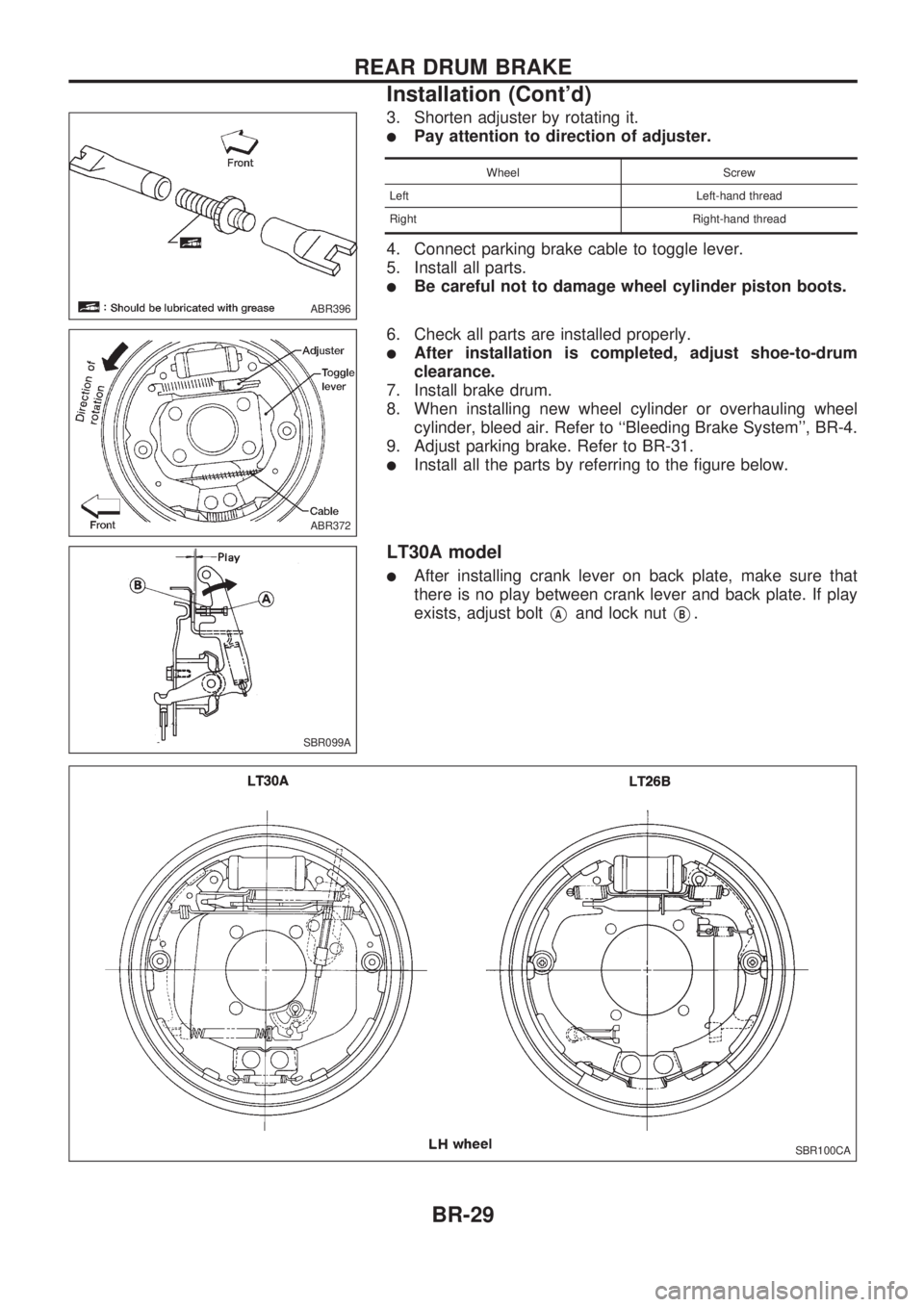
3. Shorten adjuster by rotating it.
lPay attention to direction of adjuster.
Wheel Screw
Left Left-hand thread
Right Right-hand thread
4. Connect parking brake cable to toggle lever.
5. Install all parts.
lBe careful not to damage wheel cylinder piston boots.
6. Check all parts are installed properly.
lAfter installation is completed, adjust shoe-to-drum
clearance.
7. Install brake drum.
8. When installing new wheel cylinder or overhauling wheel
cylinder, bleed air. Refer to ``Bleeding Brake System'', BR-4.
9. Adjust parking brake. Refer to BR-31.
lInstall all the parts by referring to the figure below.
LT30A model
lAfter installing crank lever on back plate, make sure that
there is no play between crank lever and back plate. If play
exists, adjust bolt
VAand lock nutVB.
ABR396
ABR372
SBR099A
SBR100CA
REAR DRUM BRAKE
Installation (Cont'd)
BR-29
Page 519 of 1659
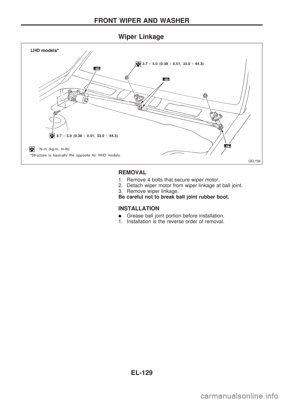
Wiper Linkage
REMOVAL
1. Remove 4 bolts that secure wiper motor.
2. Detach wiper motor from wiper linkage at ball joint.
3. Remove wiper linkage.
Be careful not to break ball joint rubber boot.
INSTALLATION
lGrease ball joint portion before installation.
1. Installation is the reverse order of removal.
GEL194
FRONT WIPER AND WASHER
EL-129
Page 787 of 1659
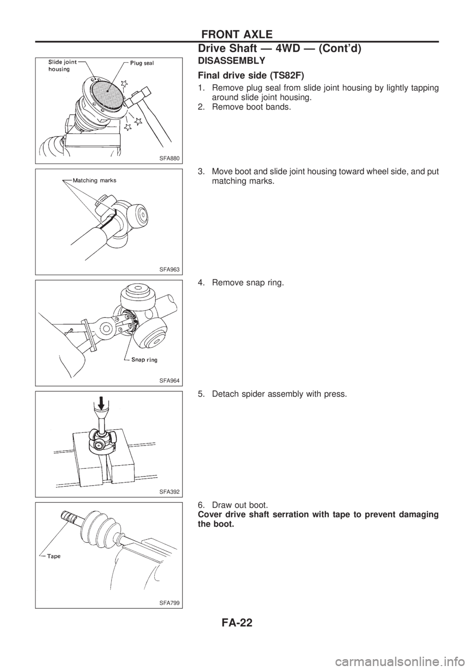
DISASSEMBLY
Final drive side (TS82F)
1. Remove plug seal from slide joint housing by lightly tapping
around slide joint housing.
2. Remove boot bands.
3. Move boot and slide joint housing toward wheel side, and put
matching marks.
4. Remove snap ring.
5. Detach spider assembly with press.
6. Draw out boot.
Cover drive shaft serration with tape to prevent damaging
the boot.
SFA880
SFA963
SFA964
SFA392
SFA799
FRONT AXLE
Drive Shaft Ð 4WD Ð (Cont'd)
FA-22
Page 788 of 1659
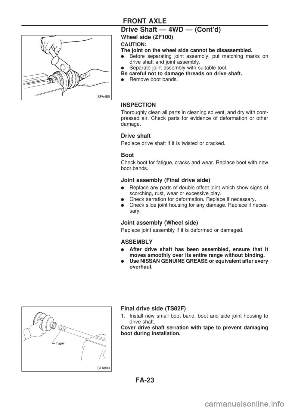
Wheel side (ZF100)
CAUTION:
The joint on the wheel side cannot be disassembled.
lBefore separating joint assembly, put matching marks on
drive shaft and joint assembly.
lSeparate joint assembly with suitable tool.
Be careful not to damage threads on drive shaft.
lRemove boot bands.
INSPECTION
Thoroughly clean all parts in cleaning solvent, and dry with com-
pressed air. Check parts for evidence of deformation or other
damage.
Drive shaft
Replace drive shaft if it is twisted or cracked.
Boot
Check boot for fatigue, cracks and wear. Replace boot with new
boot bands.
Joint assembly (Final drive side)
lReplace any parts of double offset joint which show signs of
scorching, rust, wear or excessive play.
lCheck serration for deformation. Replace if necessary.
lCheck slide joint housing for any damage. Replace if neces-
sary.
Joint assembly (Wheel side)
Replace joint assembly if it is deformed or damaged.
ASSEMBLY
lAfter drive shaft has been assembled, ensure that it
moves smoothly over its entire range without binding.
lUse NISSAN GENUINE GREASE or equivalent after every
overhaul.
Final drive side (TS82F)
1. Install new small boot band, boot and side joint housing to
drive shaft.
Cover drive shaft serration with tape to prevent damaging
boot during installation.
SFA455
SFA800
FRONT AXLE
Drive Shaft Ð 4WD Ð (Cont'd)
FA-23
Page 789 of 1659
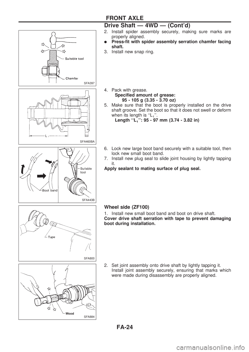
2. Install spider assembly securely, making sure marks are
properly aligned.
lPress-fit with spider assembly serration chamfer facing
shaft.
3. Install new snap ring.
4. Pack with grease.
Specified amount of grease:
95 - 105 g (3.35 - 3.70 oz)
5. Make sure that the boot is properly installed on the drive
shaft groove. Set the boot so that it does not swell or deform
when its length is ``L
1''.
Length ``L
1'': 95 - 97 mm (3.74 - 3.82 in)
6. Lock new large boot band securely with a suitable tool, then
lock new small boot band.
7. Install new plug seal to slide joint housing by lightly tapping
it.
Apply sealant to mating surface of plug seal.
Wheel side (ZF100)
1. Install new small boot band and boot on drive shaft.
Cover drive shaft serration with tape to prevent damaging
boot during installation.
2. Set joint assembly onto drive shaft by lightly tapping it.
Install joint assembly securely, ensuring that marks which
were made during disassembly are properly aligned.
SFA397
SFA460BA
SFA443B
SFA800
SFA884
FRONT AXLE
Drive Shaft Ð 4WD Ð (Cont'd)
FA-24
Page 790 of 1659
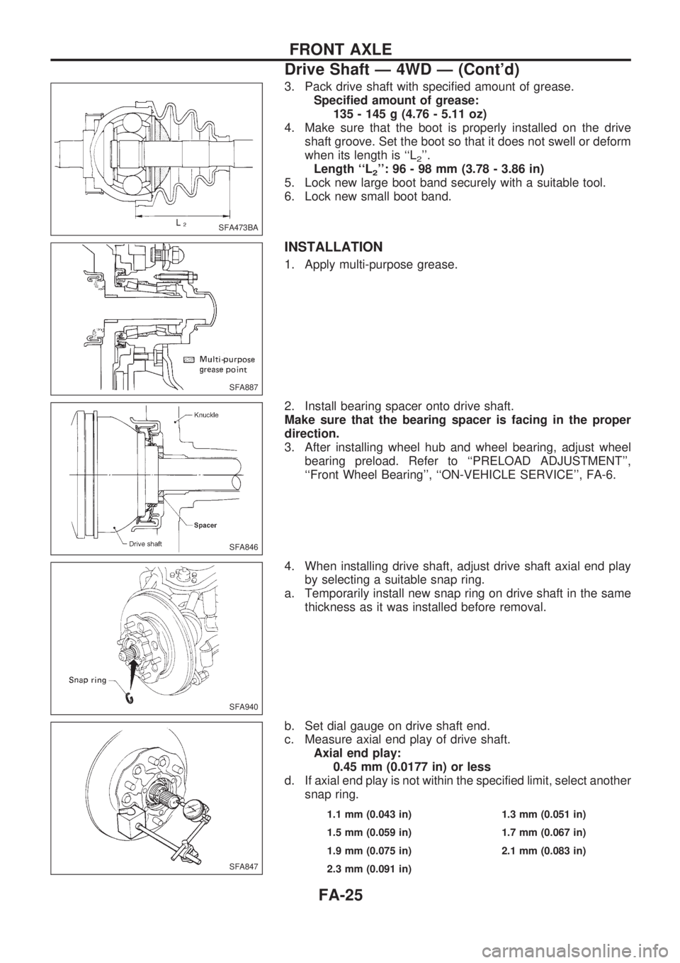
3. Pack drive shaft with specified amount of grease.
Specified amount of grease:
135 - 145 g (4.76 - 5.11 oz)
4. Make sure that the boot is properly installed on the drive
shaft groove. Set the boot so that it does not swell or deform
when its length is ``L
2''.
Length ``L
2'': 96 - 98 mm (3.78 - 3.86 in)
5. Lock new large boot band securely with a suitable tool.
6. Lock new small boot band.
INSTALLATION
1. Apply multi-purpose grease.
2. Install bearing spacer onto drive shaft.
Make sure that the bearing spacer is facing in the proper
direction.
3. After installing wheel hub and wheel bearing, adjust wheel
bearing preload. Refer to ``PRELOAD ADJUSTMENT'',
``Front Wheel Bearing'', ``ON-VEHICLE SERVICE'', FA-6.
4. When installing drive shaft, adjust drive shaft axial end play
by selecting a suitable snap ring.
a. Temporarily install new snap ring on drive shaft in the same
thickness as it was installed before removal.
b. Set dial gauge on drive shaft end.
c. Measure axial end play of drive shaft.
Axial end play:
0.45 mm (0.0177 in) or less
d. If axial end play is not within the specified limit, select another
snap ring.
1.1 mm (0.043 in) 1.3 mm (0.051 in)
1.5 mm (0.059 in) 1.7 mm (0.067 in)
1.9 mm (0.075 in) 2.1 mm (0.083 in)
2.3 mm (0.091 in)
SFA473BA
SFA887
SFA846
SFA940
SFA847
FRONT AXLE
Drive Shaft Ð 4WD Ð (Cont'd)
FA-25