engine oil NISSAN PICK-UP 1998 Repair Manual
[x] Cancel search | Manufacturer: NISSAN, Model Year: 1998, Model line: PICK-UP, Model: NISSAN PICK-UP 1998Pages: 1659, PDF Size: 53.39 MB
Page 7 of 1659
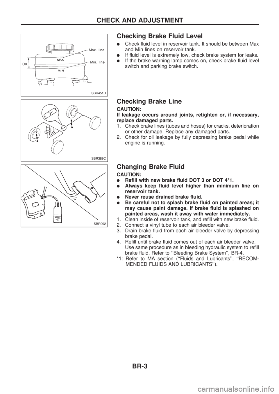
Checking Brake Fluid Level
lCheck fluid level in reservoir tank. It should be between Max
and Min lines on reservoir tank.
lIf fluid level is extremely low, check brake system for leaks.
lIf the brake warning lamp comes on, check brake fluid level
switch and parking brake switch.
Checking Brake Line
CAUTION:
If leakage occurs around joints, retighten or, if necessary,
replace damaged parts.
1. Check brake lines (tubes and hoses) for cracks, deterioration
or other damage. Replace any damaged parts.
2. Check for oil leakage by fully depressing brake pedal while
engine is running.
Changing Brake Fluid
CAUTION:
lRefill with new brake fluid DOT 3 or DOT 4*1.
lAlways keep fluid level higher than minimum line on
reservoir tank.
lNever reuse drained brake fluid.
lBe careful not to splash brake fluid on painted areas; it
may cause paint damage. If brake fluid is splashed on
painted areas, wash it away with water immediately.
1. Clean inside of reservoir tank, and refill with new brake fluid.
2. Connect a vinyl tube to each air bleeder valve.
3. Drain brake fluid from each air bleeder valve by depressing
brake pedal.
4. Refill until brake fluid comes out of each air bleeder valve.
Use same procedure as in bleeding hydraulic system to refill
brake fluid. Refer to ``Bleeding Brake System'', BR-4.
*1: Refer to MA section (``Fluids and Lubricants'', ``RECOM-
MENDED FLUIDS AND LUBRICANTS'').
SBR451D
SBR389C
SBR992
CHECK AND ADJUSTMENT
BR-3
Page 13 of 1659
INSPECTION
1. Ensure vehicle is unladen condition*.
* Fuel, radiator coolant and engine oil full. Spare tire, jack,
hand tools and mats in designated positions.
2. Have a driver sit in the driver's seat and one person sit on
the rear of the vehicle. Then have the person on the rear of
the vehicle slowly get off. This is necessary to stabilize sus-
pension deflection.
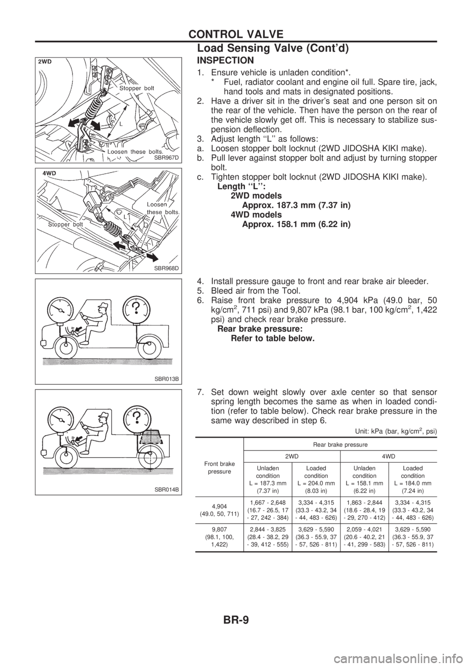
3. Adjust length ``L'' as follows:
a. Loosen stopper bolt locknut (2WD JIDOSHA KIKI make).
b. Pull lever against stopper bolt and adjust by turning stopper
bolt.
c. Tighten stopper bolt locknut (2WD JIDOSHA KIKI make).
Length ``L'':
2WD models
Approx. 187.3 mm (7.37 in)
4WD models
Approx. 158.1 mm (6.22 in)
4. Install pressure gauge to front and rear brake air bleeder.
5. Bleed air from the Tool.
6. Raise front brake pressure to 4,904 kPa (49.0 bar, 50
kg/cm
2, 711 psi) and 9,807 kPa (98.1 bar, 100 kg/cm2, 1,422
psi) and check rear brake pressure.
Rear brake pressure:
Refer to table below.
7. Set down weight slowly over axle center so that sensor
spring length becomes the same as when in loaded condi-
tion (refer to table below). Check rear brake pressure in the
same way described in step 6.
Unit: kPa (bar, kg/cm2, psi)
Front brake
pressureRear brake pressure
2WD 4WD
Unladen
condition
L = 187.3 mm
(7.37 in)Loaded
condition
L = 204.0 mm
(8.03 in)Unladen
condition
L = 158.1 mm
(6.22 in)Loaded
condition
L = 184.0 mm
(7.24 in)
4,904
(49.0, 50, 711)1,667 - 2,648
(16.7 - 26.5, 17
- 27, 242 - 384)3,334 - 4,315
(33.3 - 43.2, 34
- 44, 483 - 626)1,863 - 2,844
(18.6 - 28.4, 19
- 29, 270 - 412)3,334 - 4,315
(33.3 - 43.2, 34
- 44, 483 - 626)
9,807
(98.1, 100,
1,422)2,844 - 3,825
(28.4 - 38.2, 29
- 39, 412 - 555)3,629 - 5,590
(36.3 - 55.9, 37
- 57, 526 - 811)2,059 - 4,021
(20.6 - 40.2, 21
- 41, 299 - 583)3,629 - 5,590
(36.3 - 55.9, 37
- 57, 526 - 811)
SBR967D
SBR968D
SBR013B
SBR014B
CONTROL VALVE
Load Sensing Valve (Cont'd)
BR-9
Page 21 of 1659
Removal and Installation
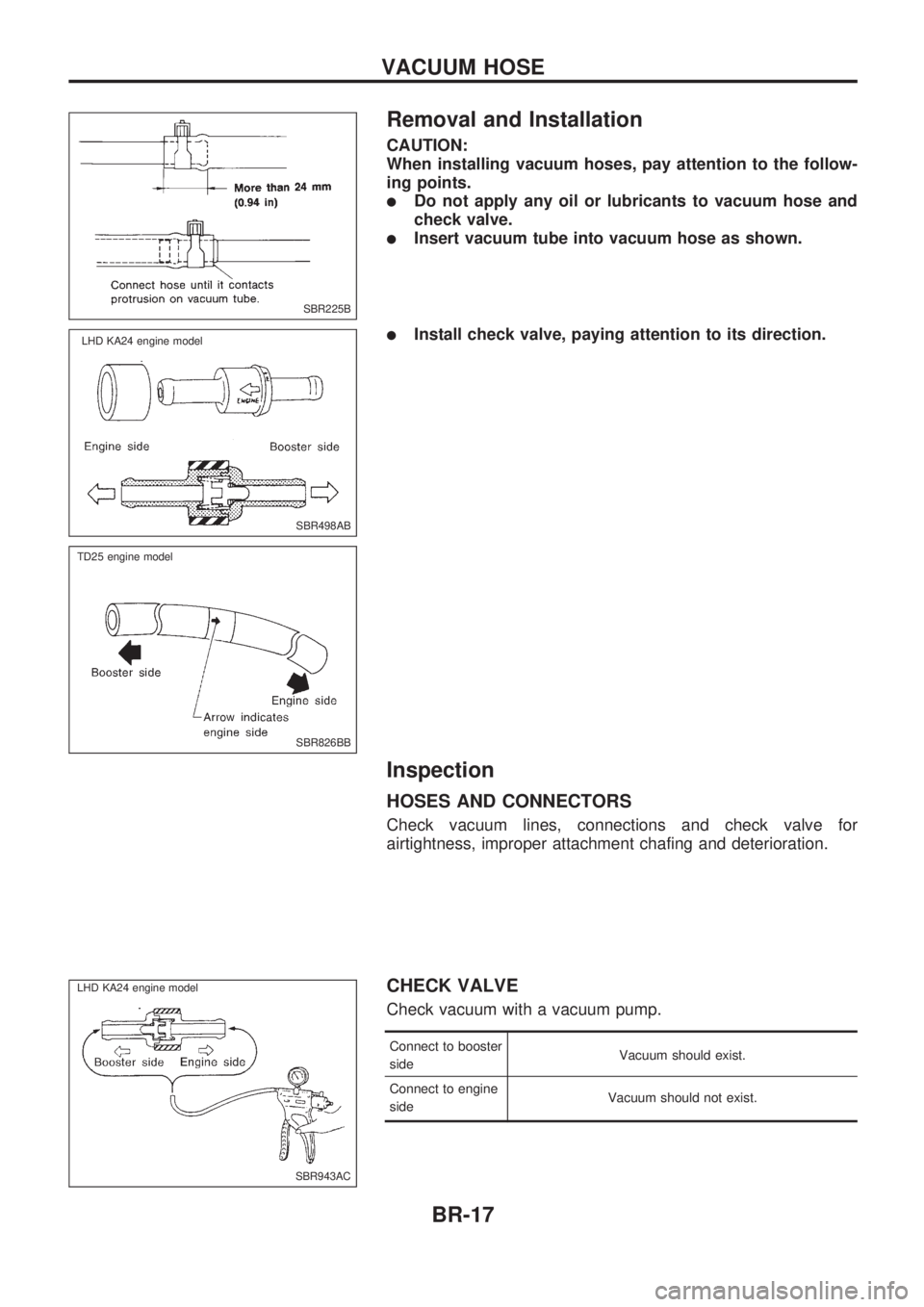
CAUTION:
When installing vacuum hoses, pay attention to the follow-
ing points.
lDo not apply any oil or lubricants to vacuum hose and
check valve.
lInsert vacuum tube into vacuum hose as shown.
lInstall check valve, paying attention to its direction.
Inspection
HOSES AND CONNECTORS
Check vacuum lines, connections and check valve for
airtightness, improper attachment chafing and deterioration.
CHECK VALVE
Check vacuum with a vacuum pump.
Connect to booster
sideVacuum should exist.
Connect to engine
sideVacuum should not exist.
SBR225B
SBR498AB
.LHD KA24 engine model
SBR826BB
.TD25 engine model
SBR943AC
.LHD KA24 engine model.
VACUUM HOSE
BR-17
Page 97 of 1659
Clutch Disc and Flywheel
INSPECTION
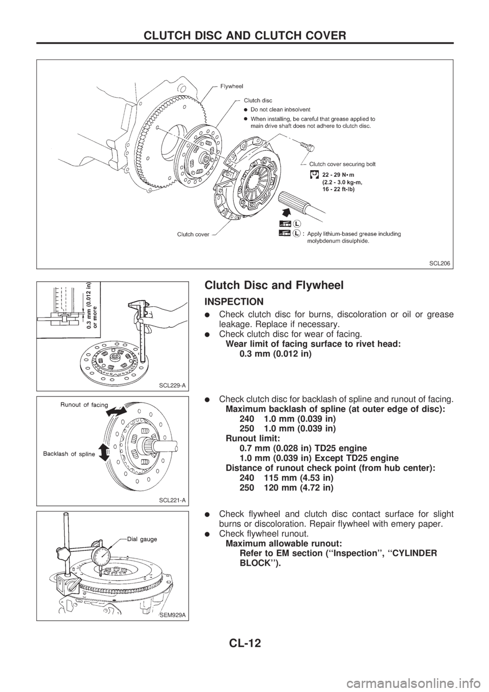
lCheck clutch disc for burns, discoloration or oil or grease
leakage. Replace if necessary.
lCheck clutch disc for wear of facing.
Wear limit of facing surface to rivet head:
0.3 mm (0.012 in)
lCheck clutch disc for backlash of spline and runout of facing.
Maximum backlash of spline (at outer edge of disc):
240 1.0 mm (0.039 in)
250 1.0 mm (0.039 in)
Runout limit:
0.7 mm (0.028 in) TD25 engine
1.0 mm (0.039 in) Except TD25 engine
Distance of runout check point (from hub center):
240 115 mm (4.53 in)
250 120 mm (4.72 in)
lCheck flywheel and clutch disc contact surface for slight
burns or discoloration. Repair flywheel with emery paper.
lCheck flywheel runout.
Maximum allowable runout:
Refer to EM section (``Inspection'', ``CYLINDER
BLOCK'').
SCL206
SCL229-A
SCL221-A
SEM929A
CLUTCH DISC AND CLUTCH COVER
CL-12
Page 151 of 1659
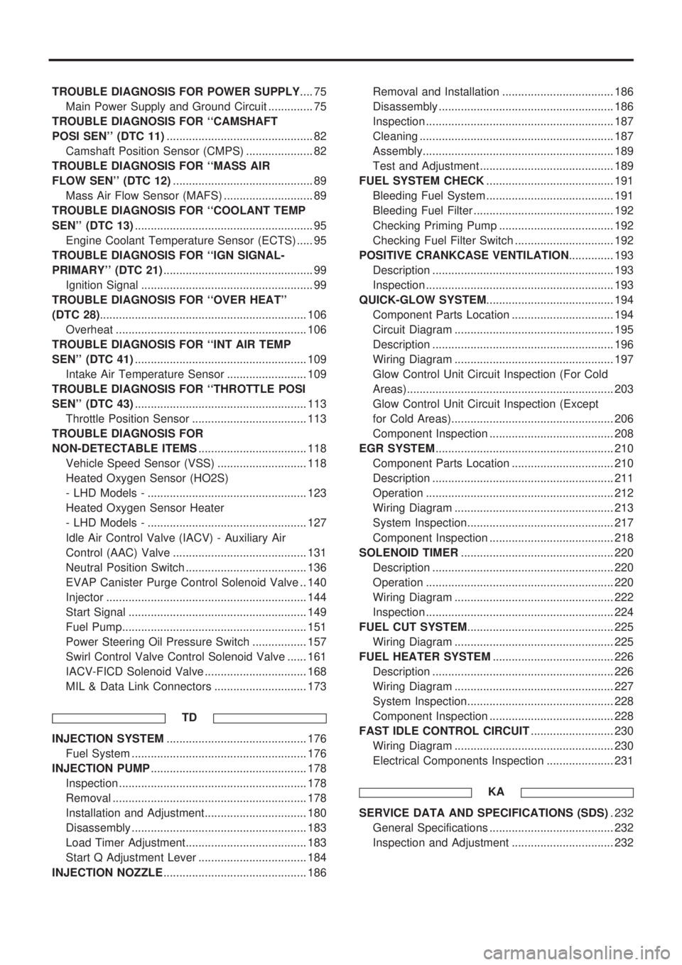
TROUBLE DIAGNOSIS FOR POWER SUPPLY.... 75
Main Power Supply and Ground Circuit .............. 75
TROUBLE DIAGNOSIS FOR ``CAMSHAFT
POSI SEN'' (DTC 11).............................................. 82
Camshaft Position Sensor (CMPS) ..................... 82
TROUBLE DIAGNOSIS FOR ``MASS AIR
FLOW SEN'' (DTC 12)............................................ 89
Mass Air Flow Sensor (MAFS) ............................ 89
TROUBLE DIAGNOSIS FOR ``COOLANT TEMP
SEN'' (DTC 13)........................................................ 95
Engine Coolant Temperature Sensor (ECTS) ..... 95
TROUBLE DIAGNOSIS FOR ``IGN SIGNAL-
PRIMARY'' (DTC 21)............................................... 99
Ignition Signal ...................................................... 99
TROUBLE DIAGNOSIS FOR ``OVER HEAT''
(DTC 28)................................................................. 106
Overheat ............................................................ 106
TROUBLE DIAGNOSIS FOR ``INT AIR TEMP
SEN'' (DTC 41)...................................................... 109
Intake Air Temperature Sensor ......................... 109
TROUBLE DIAGNOSIS FOR ``THROTTLE POSI
SEN'' (DTC 43)...................................................... 113
Throttle Position Sensor .................................... 113
TROUBLE DIAGNOSIS FOR
NON-DETECTABLE ITEMS.................................. 118
Vehicle Speed Sensor (VSS) ............................ 118
Heated Oxygen Sensor (HO2S)
- LHD Models - .................................................. 123
Heated Oxygen Sensor Heater
- LHD Models - .................................................. 127
Idle Air Control Valve (IACV) - Auxiliary Air
Control (AAC) Valve .......................................... 131
Neutral Position Switch ...................................... 136
EVAP Canister Purge Control Solenoid Valve .. 140
Injector ............................................................... 144
Start Signal ........................................................ 149
Fuel Pump.......................................................... 151
Power Steering Oil Pressure Switch ................. 157
Swirl Control Valve Control Solenoid Valve ...... 161
IACV-FICD Solenoid Valve ................................ 168
MIL & Data Link Connectors ............................. 173
TD
INJECTION SYSTEM............................................ 176
Fuel System ....................................................... 176
INJECTION PUMP................................................. 178
Inspection ........................................................... 178
Removal ............................................................. 178
Installation and Adjustment................................ 180
Disassembly ....................................................... 183
Load Timer Adjustment...................................... 183
Start Q Adjustment Lever .................................. 184
INJECTION NOZZLE............................................. 186Removal and Installation ................................... 186
Disassembly ....................................................... 186
Inspection ........................................................... 187
Cleaning ............................................................. 187
Assembly............................................................ 189
Test and Adjustment .......................................... 189
FUEL SYSTEM CHECK........................................ 191
Bleeding Fuel System ........................................ 191
Bleeding Fuel Filter ............................................ 192
Checking Priming Pump .................................... 192
Checking Fuel Filter Switch ............................... 192
POSITIVE CRANKCASE VENTILATION.............. 193
Description ......................................................... 193
Inspection ........................................................... 193
QUICK-GLOW SYSTEM........................................ 194
Component Parts Location ................................ 194
Circuit Diagram .................................................. 195
Description ......................................................... 196
Wiring Diagram .................................................. 197
Glow Control Unit Circuit Inspection (For Cold
Areas)................................................................. 203
Glow Control Unit Circuit Inspection (Except
for Cold Areas)................................................... 206
Component Inspection ....................................... 208
EGR SYSTEM........................................................ 210
Component Parts Location ................................ 210
Description ......................................................... 211
Operation ........................................................... 212
Wiring Diagram .................................................. 213
System Inspection.............................................. 217
Component Inspection ....................................... 218
SOLENOID TIMER................................................ 220
Description ......................................................... 220
Operation ........................................................... 220
Wiring Diagram .................................................. 222
Inspection ........................................................... 224
FUEL CUT SYSTEM.............................................. 225
Wiring Diagram .................................................. 225
FUEL HEATER SYSTEM...................................... 226
Description ......................................................... 226
Wiring Diagram .................................................. 227
System Inspection.............................................. 228
Component Inspection ....................................... 228
FAST IDLE CONTROL CIRCUIT.......................... 230
Wiring Diagram .................................................. 230
Electrical Components Inspection ..................... 231
KA
SERVICE DATA AND SPECIFICATIONS (SDS). 232
General Specifications ....................................... 232
Inspection and Adjustment ................................ 232
Page 155 of 1659
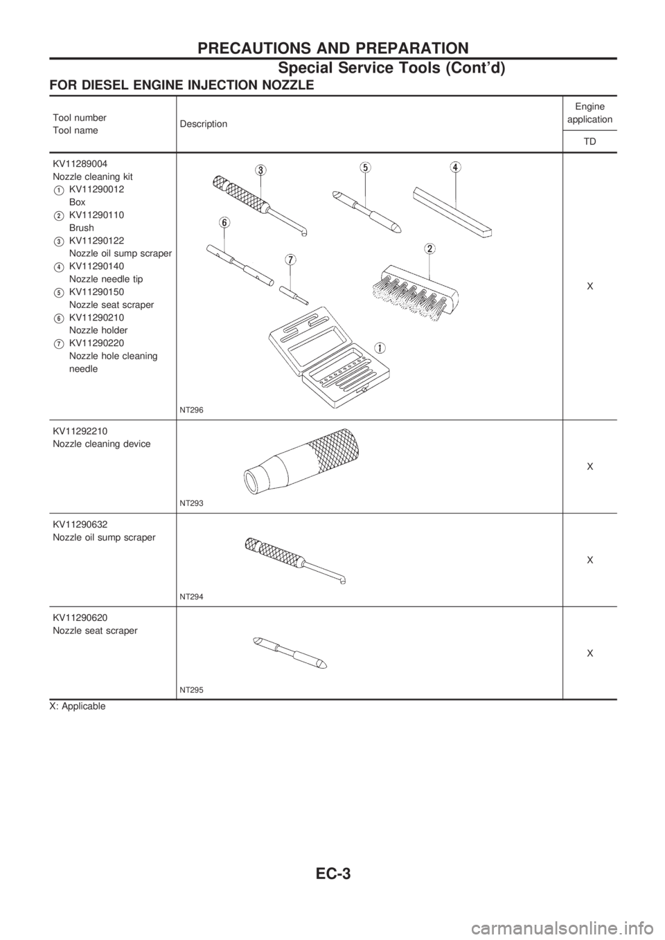
FOR DIESEL ENGINE INJECTION NOZZLE
Tool number
Tool nameDescriptionEngine
application
TD
KV11289004
Nozzle cleaning kit
V1KV11290012
Box
V2KV11290110
Brush
V3KV11290122
Nozzle oil sump scraper
V4KV11290140
Nozzle needle tip
V5KV11290150
Nozzle seat scraper
V6KV11290210
Nozzle holder
V7KV11290220
Nozzle hole cleaning
needle
NT296
X
KV11292210
Nozzle cleaning device
NT293
X
KV11290632
Nozzle oil sump scraper
NT294
X
KV11290620
Nozzle seat scraper
NT295
X
X: Applicable
PRECAUTIONS AND PREPARATION
Special Service Tools (Cont'd)
EC-3
Page 165 of 1659
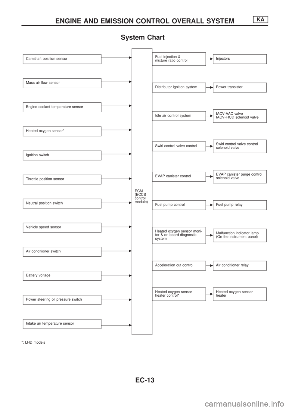
System Chart
Camshaft position sensorc
ECM
(ECCS
control
module)
Mass air flow sensorc
Engine coolant temperature sensorc
Heated oxygen sensor*c
Ignition switchc
Throttle position sensorc
Neutral position switchc
Vehicle speed sensorc
Air conditioner switchc
Battery voltagec
Power steering oil pressure switchc
Intake air temperature sensorc
*: LHD models
Fuel injection &
mixture ratio controlcInjectors
Distributor ignition systemcPower transistor
Idle air control systemcIACV-AAC valve
IACV-FICD solenoid valve
Swirl control valve controlcSwirl control valve control
solenoid valve
EVAP canister controlcEVAP canister purge control
solenoid valve
Fuel pump controlcFuel pump relay
Heated oxygen sensor moni-
tor & on board diagnostic
systemcMalfunction indicator lamp
(On the instrument panel)
Acceleration cut controlcAir conditioner relay
Heated oxygen sensor
heater control*cHeated oxygen sensor
heater
ENGINE AND EMISSION CONTROL OVERALL SYSTEMKA
EC-13
Page 175 of 1659
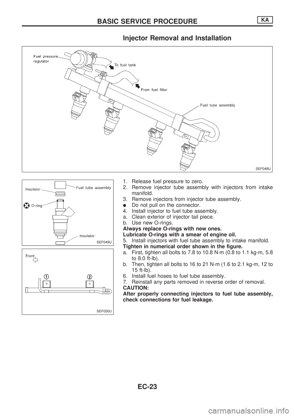
Injector Removal and Installation
1. Release fuel pressure to zero.
2. Remove injector tube assembly with injectors from intake
manifold.
3. Remove injectors from injector tube assembly.
lDo not pull on the connector.
4. Install injector to fuel tube assembly.
a. Clean exterior of injector tail piece.
b. Use new O-rings.
Always replace O-rings with new ones.
Lubricate O-rings with a smear of engine oil.
5. Install injectors with fuel tube assembly to intake manifold.
Tighten in numerical order shown in the figure.
a. First, tighten all bolts to 7.8 to 10.8 N´m (0.8 to 1.1 kg-m, 5.8
to 8.0 ft-lb).
b. Then, tighten all bolts to 16 to 21 N´m (1.6 to 2.1 kg-m, 12 to
15 ft-lb).
6. Install fuel hoses to fuel tube assembly.
7. Reinstall any parts removed in reverse order of removal.
CAUTION:
After properly connecting injectors to fuel tube assembly,
check connections for fuel leakage.
SEF048U
SEF049U
SEF050U
BASIC SERVICE PROCEDUREKA
EC-23
Page 177 of 1659
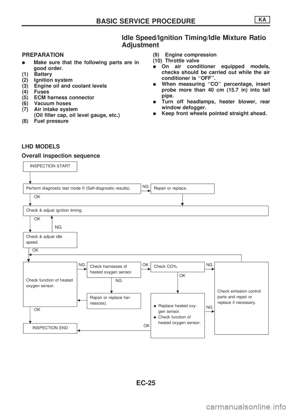
Idle Speed/Ignition Timing/Idle Mixture Ratio
Adjustment
PREPARATION
lMake sure that the following parts are in
good order.
(1) Battery
(2) Ignition system
(3) Engine oil and coolant levels
(4) Fuses
(5) ECM harness connector
(6) Vacuum hoses
(7) Air intake system
(Oil filler cap, oil level gauge, etc.)
(8) Fuel pressure(9) Engine compression
(10) Throttle valvelOn air conditioner equipped models,
checks should be carried out while the air
conditioner is ``OFF''.
lWhen measuring ``CO'' percentage, insert
probe more than 40 cm (15.7 in) into tail
pipe.
lTurn off headlamps, heater blower, rear
window defogger.
lKeep front wheels pointed straight ahead.
LHD MODELS
Overall inspection sequence
INSPECTION START
Perform diagnostic test mode II (Self-diagnostic results).
OK
cNG
Repair or replace.
.
Check & adjust ignition timing.
OKm
NG
Check & adjust idle
speed.
.
OKb
Check function of heated
oxygen sensor.
OK
cNG
Check harnesses of
heated oxygen sensor.
NG
cOK
Check CO%.
OK
.
cNG
Check emission control
parts and repair or
replace if necessary.
bRepair or replace har-
ness(es).
lReplace heated oxy-
gen sensor.
lCheck function of
heated oxygen sensor.
cNG
INSPECTION END
bOK
.
.
.
.
.
BASIC SERVICE PROCEDUREKA
EC-25
Page 199 of 1659
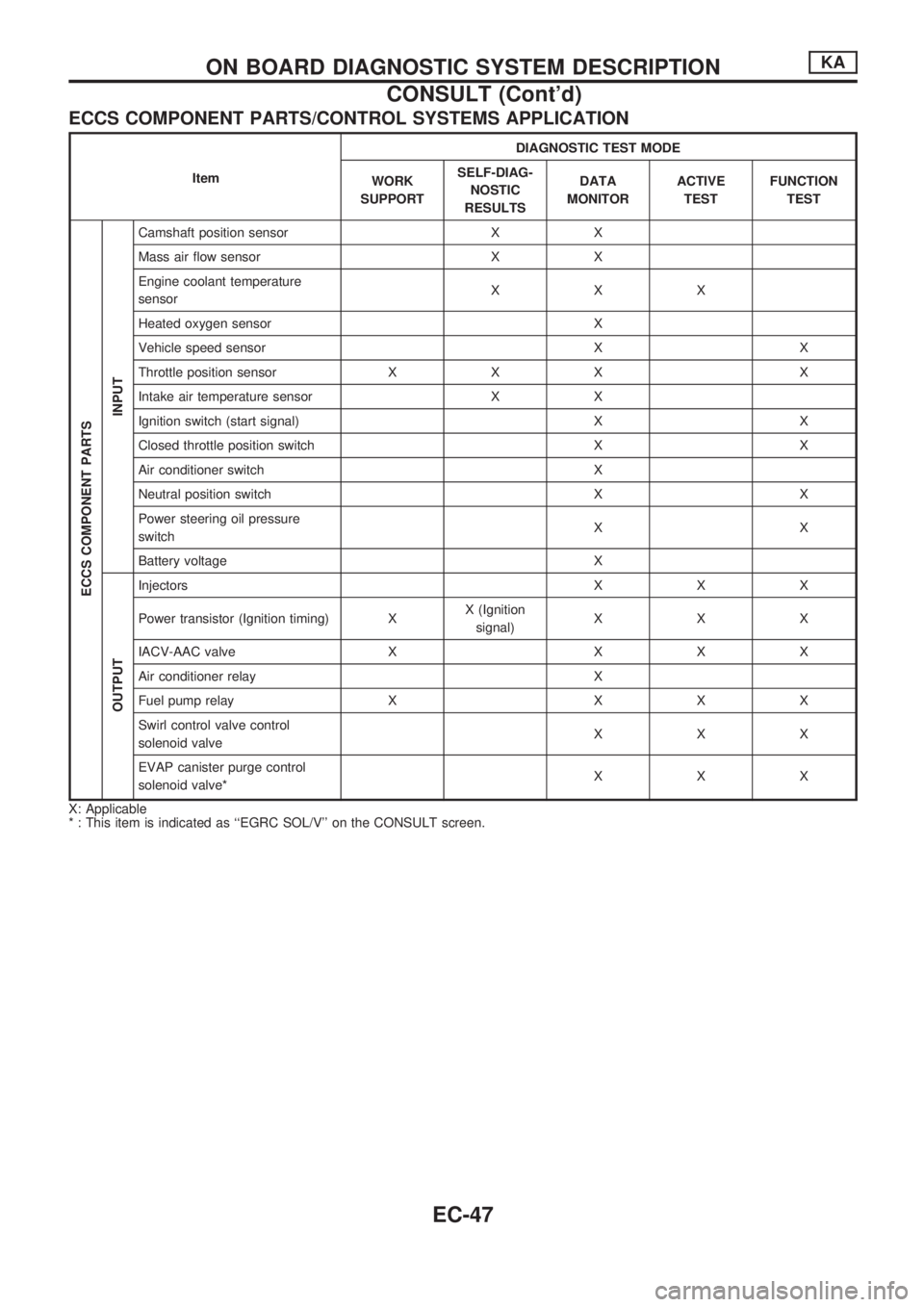
ECCS COMPONENT PARTS/CONTROL SYSTEMS APPLICATION
ItemDIAGNOSTIC TEST MODE
WORK
SUPPORTSELF-DIAG-
NOSTIC
RESULTSDATA
MONITORACTIVE
TESTFUNCTION
TEST
ECCS COMPONENT PARTS
INPUT
Camshaft position sensor X X
Mass air flow sensor X X
Engine coolant temperature
sensorXXX
Heated oxygen sensor X
Vehicle speed sensor X X
Throttle position sensor X X X X
Intake air temperature sensor X X
Ignition switch (start signal) X X
Closed throttle position switch X X
Air conditioner switch X
Neutral position switch X X
Power steering oil pressure
switchXX
Battery voltage X
OUTPUT
Injectors X X X
Power transistor (Ignition timing) XX (Ignition
signal)XXX
IACV-AAC valve X X X X
Air conditioner relay X
Fuel pump relay X X X X
Swirl control valve control
solenoid valveXXX
EVAP canister purge control
solenoid valve*XXX
X: Applicable
* : This item is indicated as ``EGRC SOL/V'' on the CONSULT screen.
ON BOARD DIAGNOSTIC SYSTEM DESCRIPTIONKA
CONSULT (Cont'd)
EC-47