set clock NISSAN PICK-UP 1998 Repair Manual
[x] Cancel search | Manufacturer: NISSAN, Model Year: 1998, Model line: PICK-UP, Model: NISSAN PICK-UP 1998Pages: 1659, PDF Size: 53.39 MB
Page 330 of 1659
Inspection
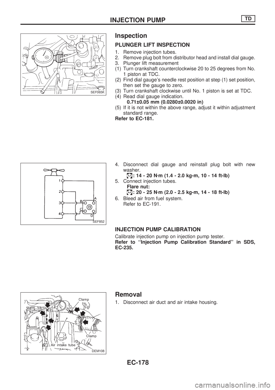
PLUNGER LIFT INSPECTION
1. Remove injection tubes.
2. Remove plug bolt from distributor head and install dial gauge.
3. Plunger lift measurement
(1) Turn crankshaft counterclockwise 20 to 25 degrees from No.
1 piston at TDC.
(2) Find dial gauge's needle rest position at step (1) set position,
then set the gauge to zero.
(3) Turn crankshaft clockwise until No. 1 piston is set at TDC.
(4) Read dial gauge indication.
0.71 0.05 mm (0.0280 0.0020 in)
(5) If it is not within the above range, adjust it within adjustment
standard range.
Refer to EC-181.
4. Disconnect dial gauge and reinstall plug bolt with new
washer.
:14-20Nzm (1.4 - 2.0 kg-m, 10 - 14 ft-lb)
5. Connect injection tubes.
Flare nut:
:20-25Nzm (2.0 - 2.5 kg-m, 14 - 18 ft-lb)
6. Bleed air from fuel system.
Refer to EC-191.
INJECTION PUMP CALIBRATION
Calibrate injection pump on injection pump tester.
Refer to ``Injection Pump Calibration Standard'' in SDS,
EC-235.
Removal
1. Disconnect air duct and air intake housing.
SEF065K
SEF852
DEM108
.
INJECTION PUMPTD
EC-178
Page 333 of 1659
2. Install injection pump.
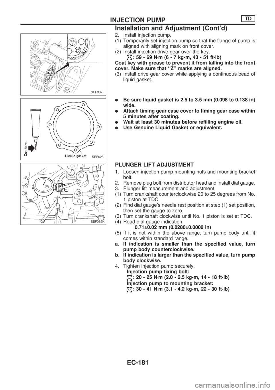
(1) Temporarily set injection pump so that the flange of pump is
aligned with aligning mark on front cover.
(2) Install injection drive gear over the key.
:59-69Nzm (6 - 7 kg-m, 43 - 51 ft-lb)
Coat key with grease to prevent it from falling into the front
cover. Make sure that ``Z'' marks are aligned.
(3) Install drive gear cover while applying a continuous bead of
liquid gasket.
lBe sure liquid gasket is 2.5 to 3.5 mm (0.098 to 0.138 in)
wide.
lAttach timing gear case cover to timing gear case within
5 minutes after coating.
lWait at least 30 minutes before refilling engine oil.
lUse Genuine Liquid Gasket or equivalent.
PLUNGER LIFT ADJUSTMENT
1. Loosen injection pump mounting nuts and mounting bracket
bolt.
2. Remove plug bolt from distributor head and install dial gauge.
3. Plunger lift measurement and adjustment
(1) Turn crankshaft counterclockwise 20 to 25 degrees from No.
1 piston at TDC.
(2) Find dial gauge's needle rest position at step (1) set position,
then set the gauge to zero.
(3) Turn crankshaft clockwise until No. 1 piston is set at TDC.
(4) Read dial gauge indication.
0.71 0.02 mm (0.0280 0.0008 in)
(5) If it is not within the above range, turn pump body until it
comes within standard range.
a. If indication is smaller than the specified value, turn
pump body counterclockwise.
b. If indication is larger than the specified value, turn pump
body clockwise.
4. Tighten injection pump securely.
Injection pump fixing bolt:
:20-25Nzm (2.0 - 2.5 kg-m, 14 - 18 ft-lb)
Injection pump to mounting bracket:
:30-41Nzm (3.1 - 4.2 kg-m, 22 - 30 ft-lb)
SEF337F
SEF626I
SEF065K
INJECTION PUMPTD
Installation and Adjustment (Cont'd)
EC-181
Page 386 of 1659
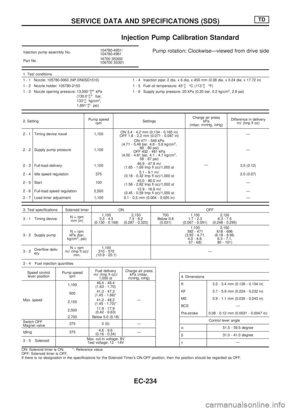
Injection Pump Calibration Standard
Injection pump assembly No.104780-4951/
104780-4961
Part No.16700 3S300/
106700 3S301Pump rotation: ClockwiseÐviewed from drive side
1. Test conditions
1 - 1 Nozzle: 105780-0060 (NP-DN0SD1510) 1 - 4 Injection pipe: 2 dia. x 6 dia. x 450 mm (0.08 dia. x 0.24 dia. x 17.72 in)
1 - 2 Nozzle holder: 105780-2150 1 - 5 Fuel oil temperature: 45
+5
0ÉC (113+9
0ÉF)
1 - 3 Nozzle opening pressure: 13,000+300
0kPa
(130.0+3.0
0bar,
133+3
0kg/cm2,
1,891+43
0psi)1 - 6 Supply pump pressure: 20 kPa (0.20 bar, 0.2 kg/cm
2, 2.8 psi)
2. SettingPump speed
rpmSettingsCharge air press
kPa
(mbar, mmHg, inHg)Difference in delivery
m!(Imp fl oz)
2 - 1 Timing device travel 1,100ON 3.4 - 4.2 mm (0.134 - 0.165 in)
OFF 1.8 - 2.2 mm (0.071 - 0.087 in)
ÐÐ
2 - 2 Supply pump pressure 1,100ON 471 - 549 kPa
(4.71 - 5.49 bar, 4.8 - 5.6 kg/cm
2,
68 - 80 psi)
OFF 402 - 461 kPa
(4.02 - 4.61 bar, 4.1 - 4.7 kg/cm
2,
58 - 67 psi)Ð
2 - 3 Full-load delivery 1,10046.9 - 47.9 m!
(1.65 - 1.69 Imp fl oz)/1,000 st3.5 (0.12)
2 - 4 Idle speed regulation 3755.1 - 9.1 m!
(0.18 - 0.32 Imp fl oz)/1,000 st2.0 (0.07)
2 - 5 Start 10045.0 - 80.0 m!
(1.58 - 2.82 Imp fl oz)/1,000 stÐ
2 - 6 Full-load speed regulation 2,50012.9 - 16.9 m!
(0.45 - 0.59 Imp fl oz)/1,000 stÐ
2 - 7 Load timer adjustment 1,100 0.1 - 0.5 mm (0.004 - 0.020 in) Ð
3. Test specifications Solenoid timer ON OFF
3 - 1 Timing deviceN = rpm
mm (in)1,100
3.3 - 4.3
(0.130 - 0.169)2,150
7.3 - 8.2
(0.287 - 0.323)700
Below 0.8
(0.031)1,100
1.7 - 2.3
(0.067 - 0.091)2,150
6.3 - 7.5
(0.248 - 0.295)
3 - 2 Supply pumpN = rpm
kPa (bar,
kg/cm
2, psi)1,100
392 - 471
(3.92 - 4.71,
4.0 - 4.8,
57 - 68)2,150
618 - 696
(6.18 - 6.96,
6.3 - 7.1,
90 - 101)
3-3Overflow deliv-
eryN = rpm
m!(Imp fl oz)/
min.1,100
310 - 570
(10.9 - 20.1)Ð
3 - 4 Fuel injection quantities
Speed control
lever positionPump speed
rpmFuel delivery
m!(Imp fl oz)/
1,000 stCharge air press
kPa (mbar,
mmHg, inHg)
Max. speed1,10046.4 - 48.4
(1.63 - 1.70)
Ð 50041.3 - 47.3
(1.45 - 1.66)*
2,15041.2 - 48.2
(1.45 - 1.70)*
2,50011.9 - 17.9
(0.42 - 0.63)
2,700 Below 5.0 (0.18)
Switch OFF
Magnet valve375 0 (0) Ð
Idling 3754.6 - 9.6
(0.16 - 0.34)Ð
3 - 5 SolenoidMax. cut-in voltage: 8V
Test voltage: 12 - 14V
ON: Solenoid timer is ON. *: Reference value
OFF: Solenoid timer is OFF.
If there is no designation in the specifications for the Solenoid Timer's ON-OFF position, then the position should be regarded as OFF.
4. Dimensions
K 3.2 - 3.4 mm (0.126 - 0.134 in)
KF 5.7 - 5.9 mm (0.224 - 0.232 in)
MS 0.9 - 1.1 mm (0.035 - 0.043 in)
BCS Ð
Pre-stroke 0.08 - 0.12 mm (0.0031 - 0.0047 in)
Control lever angle
a51.5 - 59.5 degree
b31.0 - 41.0 degree
gÐ
SERVICE DATA AND SPECIFICATIONS (SDS)TD
EC-234
Page 662 of 1659
Inspection
lCheck for cracks and excessive wear at roller links.
Replace chain if necessary.
Installation
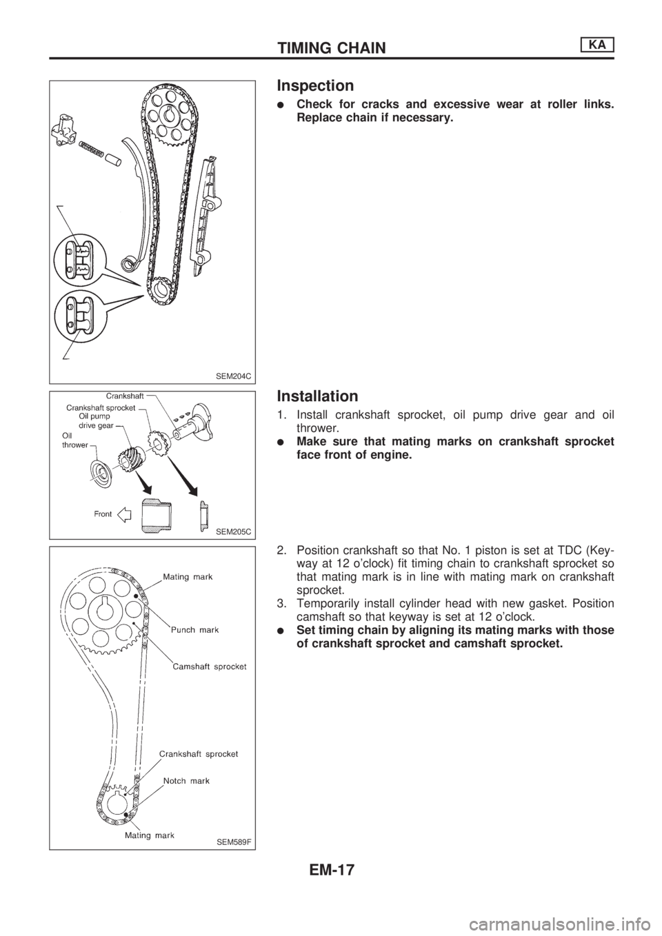
1. Install crankshaft sprocket, oil pump drive gear and oil
thrower.
lMake sure that mating marks on crankshaft sprocket
face front of engine.
2. Position crankshaft so that No. 1 piston is set at TDC (Key-
way at 12 o'clock) fit timing chain to crankshaft sprocket so
that mating mark is in line with mating mark on crankshaft
sprocket.
3. Temporarily install cylinder head with new gasket. Position
camshaft so that keyway is set at 12 o'clock.
lSet timing chain by aligning its mating marks with those
of crankshaft sprocket and camshaft sprocket.
SEM204C
SEM205C
SEM589F
TIMING CHAINKA
EM-17
Page 679 of 1659
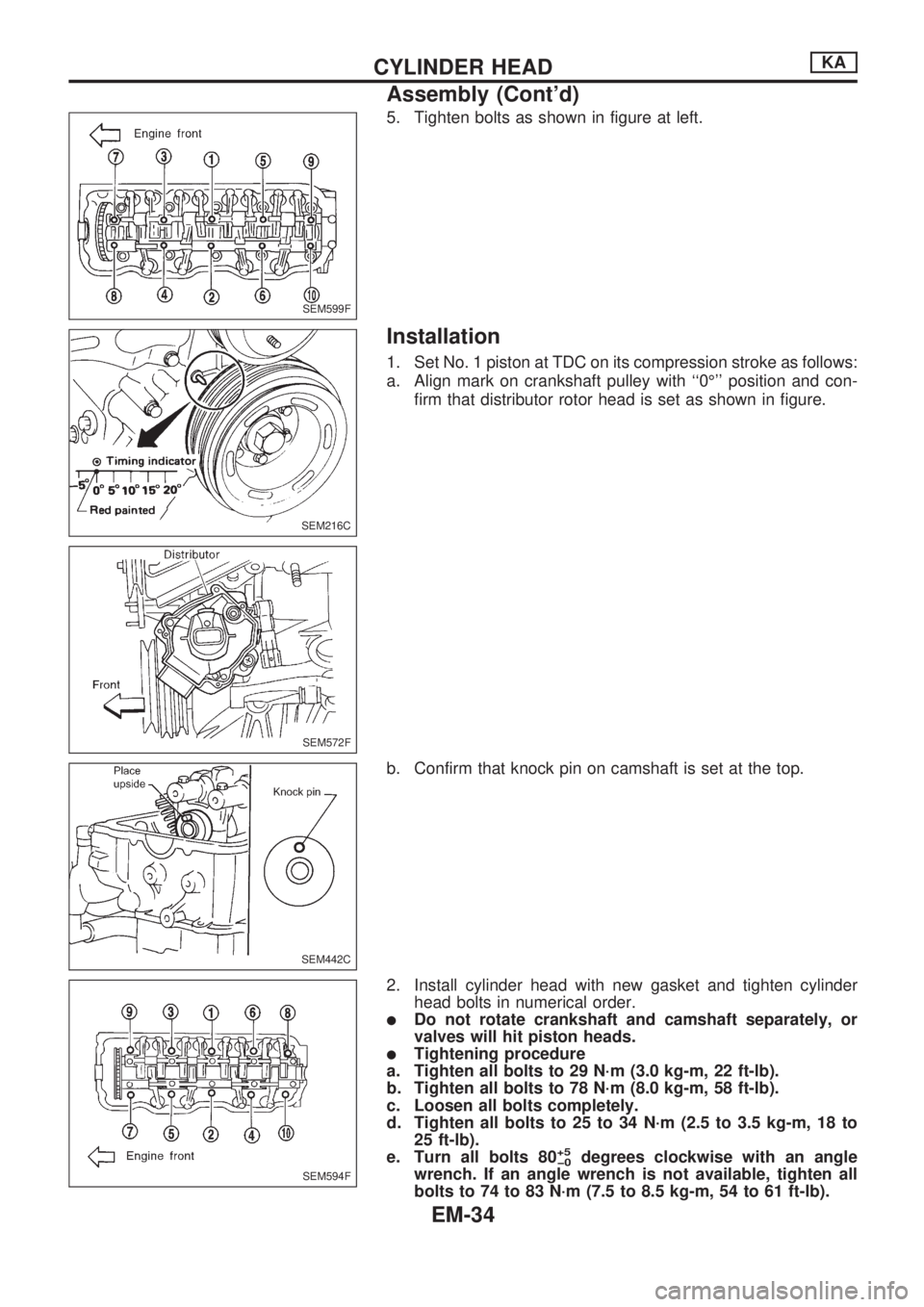
5. Tighten bolts as shown in figure at left.
Installation
1. Set No. 1 piston at TDC on its compression stroke as follows:
a. Align mark on crankshaft pulley with ``0É'' position and con-
firm that distributor rotor head is set as shown in figure.
b. Confirm that knock pin on camshaft is set at the top.
2. Install cylinder head with new gasket and tighten cylinder
head bolts in numerical order.
lDo not rotate crankshaft and camshaft separately, or
valves will hit piston heads.
lTightening procedure
a. Tighten all bolts to 29 N´m (3.0 kg-m, 22 ft-lb).
b. Tighten all bolts to 78 N´m (8.0 kg-m, 58 ft-lb).
c. Loosen all bolts completely.
d. Tighten all bolts to 25 to 34 N´m (2.5 to 3.5 kg-m, 18 to
25 ft-lb).
e. Turn all bolts 80
+5
þ0degrees clockwise with an angle
wrench. If an angle wrench is not available, tighten all
bolts to 74 to 83 N´m (7.5 to 8.5 kg-m, 54 to 61 ft-lb).
SEM599F
SEM216C
SEM572F
SEM442C
SEM594F
CYLINDER HEADKA
Assembly (Cont'd)
EM-34
Page 1570 of 1659
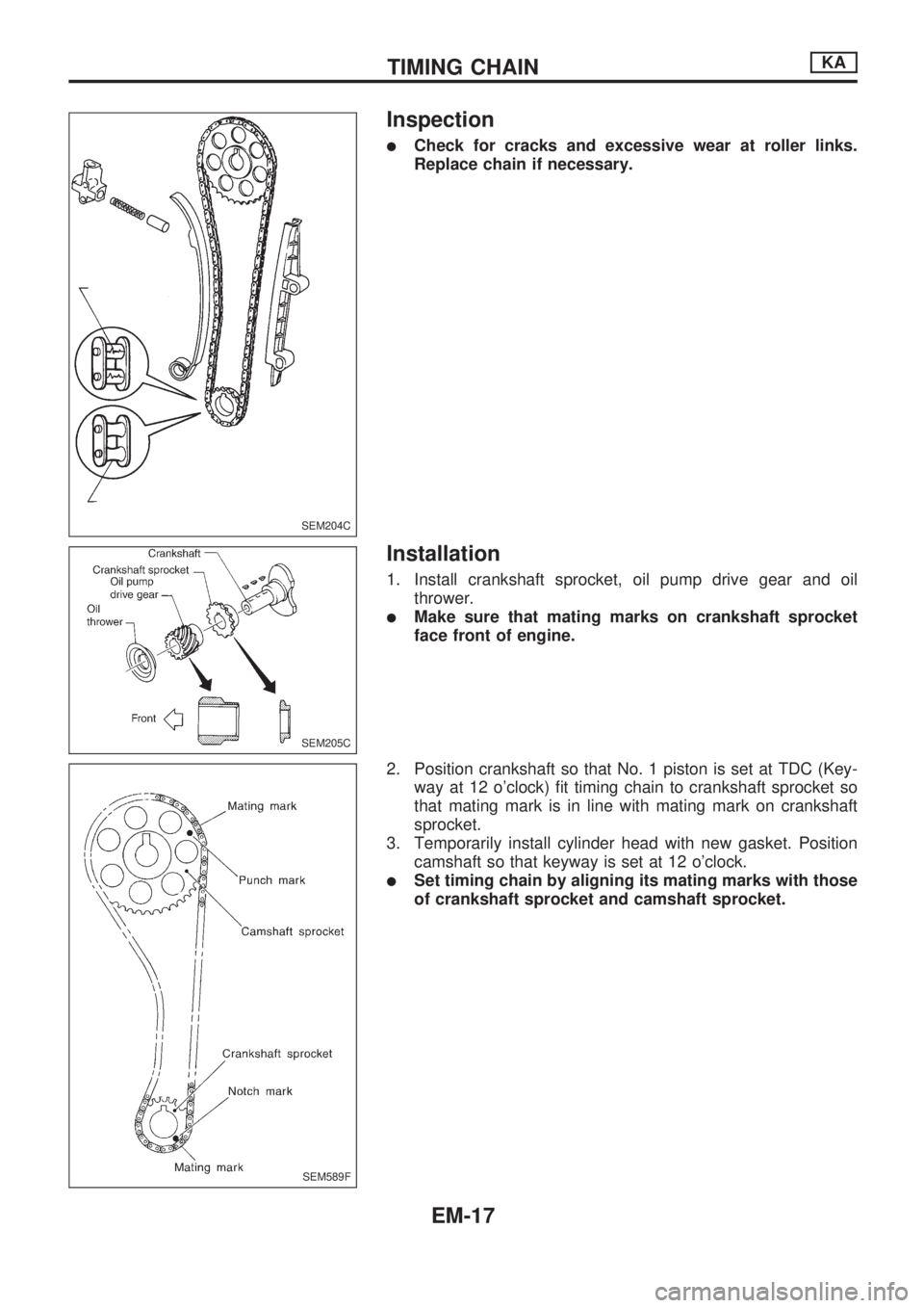
Inspection
lCheck for cracks and excessive wear at roller links.
Replace chain if necessary.
Installation
1. Install crankshaft sprocket, oil pump drive gear and oil
thrower.
lMake sure that mating marks on crankshaft sprocket
face front of engine.
2. Position crankshaft so that No. 1 piston is set at TDC (Key-
way at 12 o'clock) fit timing chain to crankshaft sprocket so
that mating mark is in line with mating mark on crankshaft
sprocket.
3. Temporarily install cylinder head with new gasket. Position
camshaft so that keyway is set at 12 o'clock.
lSet timing chain by aligning its mating marks with those
of crankshaft sprocket and camshaft sprocket.
SEM204C
SEM205C
SEM589F
TIMING CHAINKA
EM-17
Page 1587 of 1659
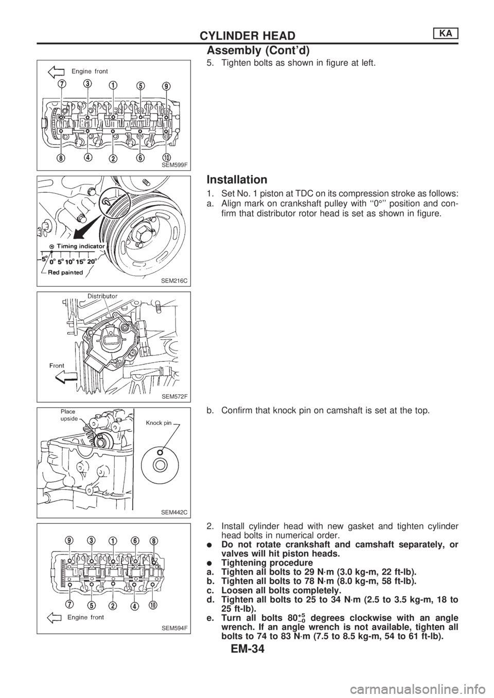
5. Tighten bolts as shown in figure at left.
Installation
1. Set No. 1 piston at TDC on its compression stroke as follows:
a. Align mark on crankshaft pulley with ``0É'' position and con-
firm that distributor rotor head is set as shown in figure.
b. Confirm that knock pin on camshaft is set at the top.
2. Install cylinder head with new gasket and tighten cylinder
head bolts in numerical order.
lDo not rotate crankshaft and camshaft separately, or
valves will hit piston heads.
lTightening procedure
a. Tighten all bolts to 29 N´m (3.0 kg-m, 22 ft-lb).
b. Tighten all bolts to 78 N´m (8.0 kg-m, 58 ft-lb).
c. Loosen all bolts completely.
d. Tighten all bolts to 25 to 34 N´m (2.5 to 3.5 kg-m, 18 to
25 ft-lb).
e. Turn all bolts 80
+5
þ0degrees clockwise with an angle
wrench. If an angle wrench is not available, tighten all
bolts to 74 to 83 N´m (7.5 to 8.5 kg-m, 54 to 61 ft-lb).
SEM599F
SEM216C
SEM572F
SEM442C
SEM594F
CYLINDER HEADKA
Assembly (Cont'd)
EM-34