engine overheat NISSAN PICK-UP 1998 Repair Manual
[x] Cancel search | Manufacturer: NISSAN, Model Year: 1998, Model line: PICK-UP, Model: NISSAN PICK-UP 1998Pages: 1659, PDF Size: 53.39 MB
Page 151 of 1659
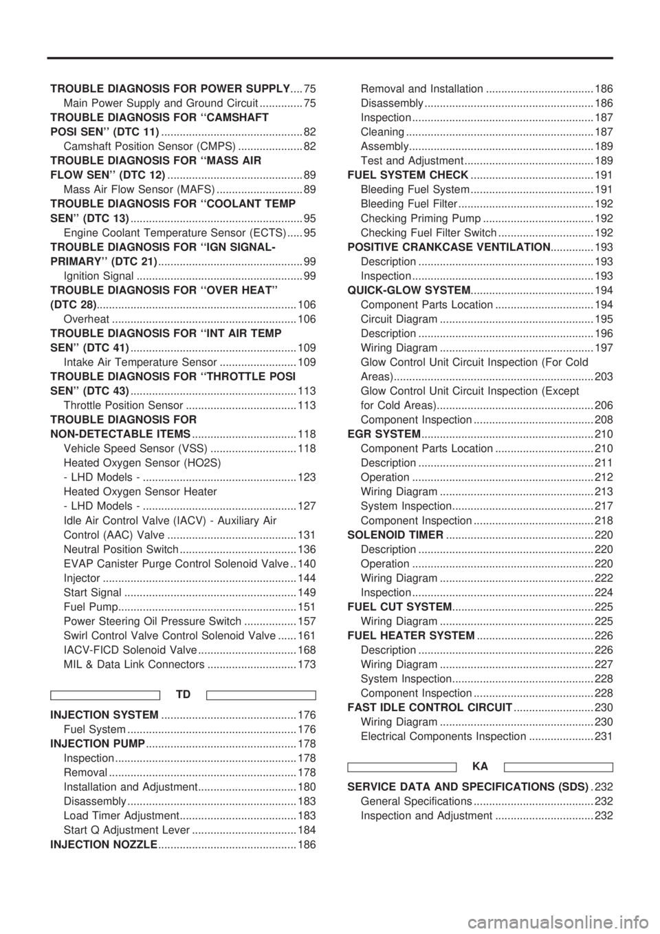
TROUBLE DIAGNOSIS FOR POWER SUPPLY.... 75
Main Power Supply and Ground Circuit .............. 75
TROUBLE DIAGNOSIS FOR ``CAMSHAFT
POSI SEN'' (DTC 11).............................................. 82
Camshaft Position Sensor (CMPS) ..................... 82
TROUBLE DIAGNOSIS FOR ``MASS AIR
FLOW SEN'' (DTC 12)............................................ 89
Mass Air Flow Sensor (MAFS) ............................ 89
TROUBLE DIAGNOSIS FOR ``COOLANT TEMP
SEN'' (DTC 13)........................................................ 95
Engine Coolant Temperature Sensor (ECTS) ..... 95
TROUBLE DIAGNOSIS FOR ``IGN SIGNAL-
PRIMARY'' (DTC 21)............................................... 99
Ignition Signal ...................................................... 99
TROUBLE DIAGNOSIS FOR ``OVER HEAT''
(DTC 28)................................................................. 106
Overheat ............................................................ 106
TROUBLE DIAGNOSIS FOR ``INT AIR TEMP
SEN'' (DTC 41)...................................................... 109
Intake Air Temperature Sensor ......................... 109
TROUBLE DIAGNOSIS FOR ``THROTTLE POSI
SEN'' (DTC 43)...................................................... 113
Throttle Position Sensor .................................... 113
TROUBLE DIAGNOSIS FOR
NON-DETECTABLE ITEMS.................................. 118
Vehicle Speed Sensor (VSS) ............................ 118
Heated Oxygen Sensor (HO2S)
- LHD Models - .................................................. 123
Heated Oxygen Sensor Heater
- LHD Models - .................................................. 127
Idle Air Control Valve (IACV) - Auxiliary Air
Control (AAC) Valve .......................................... 131
Neutral Position Switch ...................................... 136
EVAP Canister Purge Control Solenoid Valve .. 140
Injector ............................................................... 144
Start Signal ........................................................ 149
Fuel Pump.......................................................... 151
Power Steering Oil Pressure Switch ................. 157
Swirl Control Valve Control Solenoid Valve ...... 161
IACV-FICD Solenoid Valve ................................ 168
MIL & Data Link Connectors ............................. 173
TD
INJECTION SYSTEM............................................ 176
Fuel System ....................................................... 176
INJECTION PUMP................................................. 178
Inspection ........................................................... 178
Removal ............................................................. 178
Installation and Adjustment................................ 180
Disassembly ....................................................... 183
Load Timer Adjustment...................................... 183
Start Q Adjustment Lever .................................. 184
INJECTION NOZZLE............................................. 186Removal and Installation ................................... 186
Disassembly ....................................................... 186
Inspection ........................................................... 187
Cleaning ............................................................. 187
Assembly............................................................ 189
Test and Adjustment .......................................... 189
FUEL SYSTEM CHECK........................................ 191
Bleeding Fuel System ........................................ 191
Bleeding Fuel Filter ............................................ 192
Checking Priming Pump .................................... 192
Checking Fuel Filter Switch ............................... 192
POSITIVE CRANKCASE VENTILATION.............. 193
Description ......................................................... 193
Inspection ........................................................... 193
QUICK-GLOW SYSTEM........................................ 194
Component Parts Location ................................ 194
Circuit Diagram .................................................. 195
Description ......................................................... 196
Wiring Diagram .................................................. 197
Glow Control Unit Circuit Inspection (For Cold
Areas)................................................................. 203
Glow Control Unit Circuit Inspection (Except
for Cold Areas)................................................... 206
Component Inspection ....................................... 208
EGR SYSTEM........................................................ 210
Component Parts Location ................................ 210
Description ......................................................... 211
Operation ........................................................... 212
Wiring Diagram .................................................. 213
System Inspection.............................................. 217
Component Inspection ....................................... 218
SOLENOID TIMER................................................ 220
Description ......................................................... 220
Operation ........................................................... 220
Wiring Diagram .................................................. 222
Inspection ........................................................... 224
FUEL CUT SYSTEM.............................................. 225
Wiring Diagram .................................................. 225
FUEL HEATER SYSTEM...................................... 226
Description ......................................................... 226
Wiring Diagram .................................................. 227
System Inspection.............................................. 228
Component Inspection ....................................... 228
FAST IDLE CONTROL CIRCUIT.......................... 230
Wiring Diagram .................................................. 230
Electrical Components Inspection ..................... 231
KA
SERVICE DATA AND SPECIFICATIONS (SDS). 232
General Specifications ....................................... 232
Inspection and Adjustment ................................ 232
Page 214 of 1659
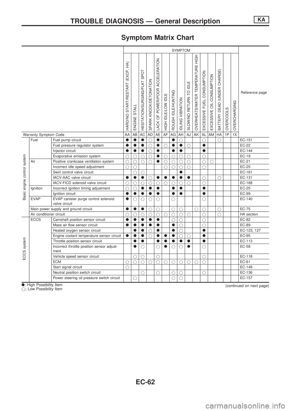
Symptom Matrix Chart
SYMPTOM
Reference page
HARD/NO START/RESTART (EXCP. HA)
ENGINE STALL
HESITATION/SURGING/FLAT SPOT
SPARK KNOCK/DETONATION
LACK OF POWER/POOR ACCELERATION
HIGH IDLE/LOW IDLE
ROUGH IDLE/HUNTING
IDLING VIBRATION
SLOW/NO RETURN TO IDLE
OVERHEATS/WATER TEMPERATURE HIGH
EXCESSIVE FUEL CONSUMPTION
EXCESSIVE OIL CONSUMPTION
BATTERY DEAD (UNDER CHARGE)
OVERCOOLS
OVERCHARGING
Warranty Symptom Code AA AB AC AD AE AF AG AH AJ AK AL AM HA 1P 1X
Basic engine control system
Fuel Fuel pump circuitllljlljjjEC-151
Fuel pressure regulator system
llljljlljlEC-22
Injector circuit
llljlll lEC-144
Evaporative emission systemjjjj
ljjjj jEC-19
Air Positive crankcase ventilation systemjjjj
ljjjj jjEC-21
Incorrect idle speed adjustmentjj jjjj jEC-25
Swirl control valve circuitjj
lEC-161
IACV-AAC valve circuit
llljllllljjEC-131
IACV-FICD solenoid valve circuitjjjjjjjjj jEC-168
Ignition Incorrect ignition timing adjustmentjj
lll ll lEC-25
Ignition circuit
lllll ll lEC-99
EVAP EVAP canister purge control solenoid
valve circuit
ljjjj j jEC-140
Main power supply and ground circuit
llljj jj jj jEC-75
Air conditioner circuitjjjjjjjjj j jHA section
ECCS system
ECCS Camshaft position sensor circuitllllljj jEC-82
Mass air flow sensor circuit
lllll ljjEC-89
Heated oxygen sensor circuit
lljlljlEC-123, 127
Engine coolant temperature sensor circuit
llljllljjlEC-95
Throttle position sensor circuit
ll lllll lEC-113
Incorrect throttle position sensor adjust-
ment
ljjljjljEC-58
Vehicle speed sensor circuitjj j jEC-118
ECMjjjjjjjjjjjEC-61
Start signal circuitjEC-149
Neutral position switch circuitjjjj jEC-136
Power steering oil pressure switch circuitjjjEC-157
l; High Possibility Item
j; Low Possibility Item(continued on next page)
TROUBLE DIAGNOSIS Ð General DescriptionKA
EC-62
Page 215 of 1659
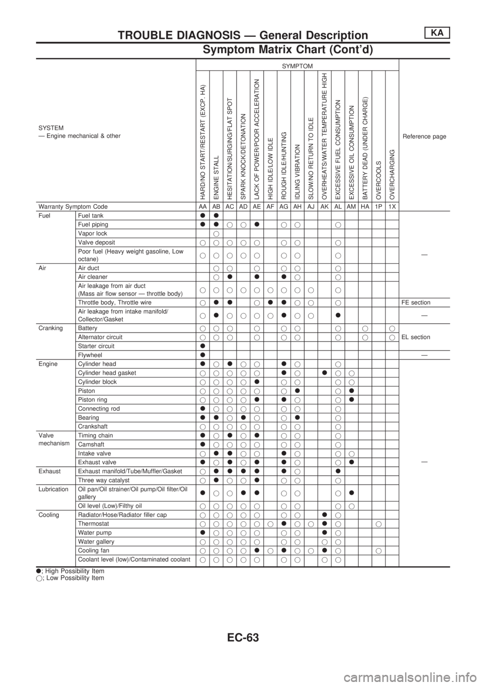
SYSTEM
Ð Engine mechanical & otherSYMPTOM
Reference page
HARD/NO START/RESTART (EXCP. HA)
ENGINE STALL
HESITATION/SURGING/FLAT SPOT
SPARK KNOCK/DETONATION
LACK OF POWER/POOR ACCELERATION
HIGH IDLE/LOW IDLE
ROUGH IDLE/HUNTING
IDLING VIBRATION
SLOW/NO RETURN TO IDLE
OVERHEATS/WATER TEMPERATURE HIGH
EXCESSIVE FUEL CONSUMPTION
EXCESSIVE OIL CONSUMPTION
BATTERY DEAD (UNDER CHARGE)
OVERCOOLS
OVERCHARGING
Warranty Symptom Code AA AB AC AD AE AF AG AH AJ AK AL AM HA 1P 1X
Fuel Fuel tank
ll
Ð Fuel piping
lljjljj j
Vapor lockj
Valve depositjjjjj jj j
Poor fuel (Heavy weight gasoline, Low
octane)jjjjj jj j
Air Air ductjjjjj j
Air cleanerj
llljj
Air leakage from air duct
(Mass air flow sensor Ð throttle body)jjjjjjjjj j
Throttle body, Throttle wirej
lljlljj jFE section
Air leakage from intake manifold/
Collector/Gasketj
ljjjjljjlÐ
Cranking Batteryjjjjjj jjj
EL section Alternator circuitjjjjjj jjj
Starter circuit
l
FlywheellÐ
Engine Cylinder head
ljljjljj
Ð Cylinder head gasketjjjjj
ljljj
Cylinder blockjjjj
ljj jj
Pistonjjjjj j
ljl
Piston ringjjjjlljjl
Connecting rodljjjj jj j
Bearing
lljljjlj
Crankshaftjjjjj jj j
Valve
mechanismTiming chain
ljljljj j
Camshaft
ljjjj jj j
Intake valvej
lljjljjj
Exhaust valve
ljljlljjl
Exhaust Exhaust manifold/Tube/Muffler/Gasketjllll ljl
Three way catalystjljjljj j
Lubrication Oil pan/Oil strainer/Oil pump/Oil filter/Oil
gallery
ljjlljj jl
Oil level (Low)/Filthy oiljjjjj jj jj
Cooling Radiator/Hose/Radiator filler capjjjjj jj
lj
Thermostatjjjjjj
ljjljj
Water pump
ljjjj jjlj
Water galleryjjjjj jj jj
Cooling fanjjjj
ljljjljj
Coolant level (low)/Contaminated coolantjjjjj jj jj
l; High Possibility Item
j; Low Possibility Item
TROUBLE DIAGNOSIS Ð General DescriptionKA
Symptom Matrix Chart (Cont'd)
EC-63
Page 258 of 1659
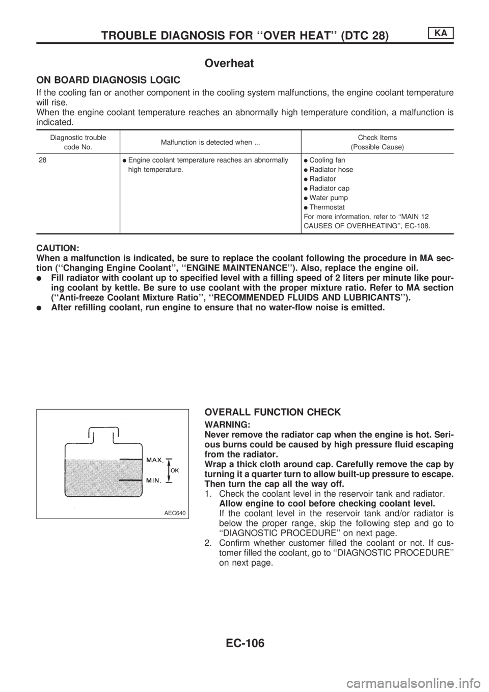
Overheat
ON BOARD DIAGNOSIS LOGIC
If the cooling fan or another component in the cooling system malfunctions, the engine coolant temperature
will rise.
When the engine coolant temperature reaches an abnormally high temperature condition, a malfunction is
indicated.
Diagnostic trouble
code No.Malfunction is detected when ...Check Items
(Possible Cause)
28
lEngine coolant temperature reaches an abnormally
high temperature.lCooling fan
lRadiator hose
lRadiator
lRadiator cap
lWater pump
lThermostat
For more information, refer to ``MAIN 12
CAUSES OF OVERHEATING'', EC-108.
CAUTION:
When a malfunction is indicated, be sure to replace the coolant following the procedure in MA sec-
tion (``Changing Engine Coolant'', ``ENGINE MAINTENANCE''). Also, replace the engine oil.
lFill radiator with coolant up to specified level with a filling speed of 2 liters per minute like pour-
ing coolant by kettle. Be sure to use coolant with the proper mixture ratio. Refer to MA section
(``Anti-freeze Coolant Mixture Ratio'', ``RECOMMENDED FLUIDS AND LUBRICANTS'').
lAfter refilling coolant, run engine to ensure that no water-flow noise is emitted.
OVERALL FUNCTION CHECK
WARNING:
Never remove the radiator cap when the engine is hot. Seri-
ous burns could be caused by high pressure fluid escaping
from the radiator.
Wrap a thick cloth around cap. Carefully remove the cap by
turning it a quarter turn to allow built-up pressure to escape.
Then turn the cap all the way off.
1. Check the coolant level in the reservoir tank and radiator.
Allow engine to cool before checking coolant level.
If the coolant level in the reservoir tank and/or radiator is
below the proper range, skip the following step and go to
``DIAGNOSTIC PROCEDURE'' on next page.
2. Confirm whether customer filled the coolant or not. If cus-
tomer filled the coolant, go to ``DIAGNOSTIC PROCEDURE''
on next page.
AEC640
TROUBLE DIAGNOSIS FOR ``OVER HEAT'' (DTC 28)KA
EC-106
Page 259 of 1659
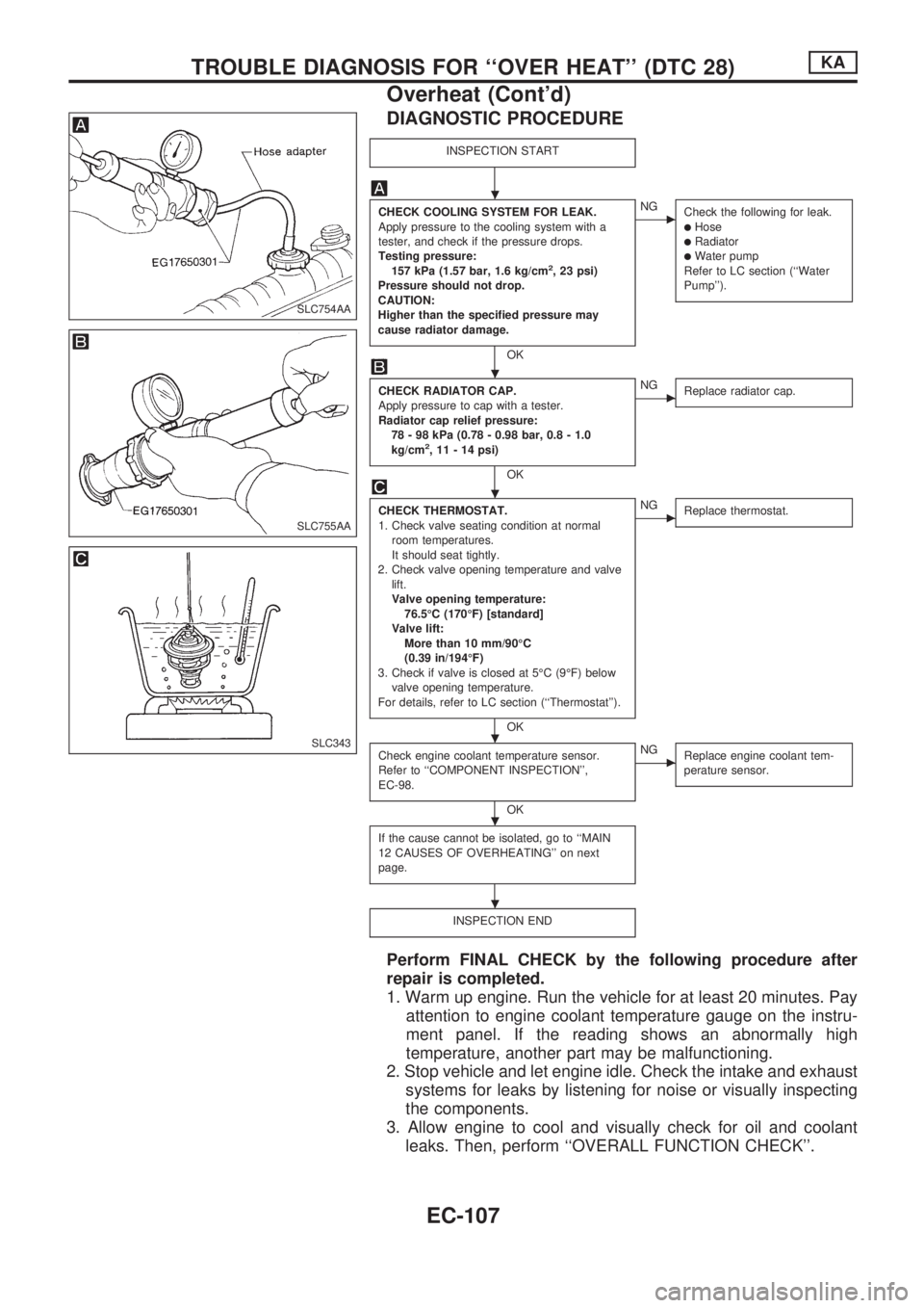
DIAGNOSTIC PROCEDURE
INSPECTION START
CHECK COOLING SYSTEM FOR LEAK.
Apply pressure to the cooling system with a
tester, and check if the pressure drops.
Testing pressure:
157 kPa (1.57 bar, 1.6 kg/cm
2, 23 psi)
Pressure should not drop.
CAUTION:
Higher than the specified pressure may
cause radiator damage.
OK
cNG
Check the following for leak.
lHoselRadiatorlWater pump
Refer to LC section (``Water
Pump'').
CHECK RADIATOR CAP.
Apply pressure to cap with a tester.
Radiator cap relief pressure:
78 - 98 kPa (0.78 - 0.98 bar, 0.8 - 1.0
kg/cm
2, 11 - 14 psi)
OK
cNG
Replace radiator cap.
CHECK THERMOSTAT.
1. Check valve seating condition at normal
room temperatures.
It should seat tightly.
2. Check valve opening temperature and valve
lift.
Valve opening temperature:
76.5ÉC (170ÉF) [standard]
Valve lift:
More than 10 mm/90ÉC
(0.39 in/194ÉF)
3. Check if valve is closed at 5ÉC (9ÉF) below
valve opening temperature.
For details, refer to LC section (``Thermostat'').
OK
cNG
Replace thermostat.
Check engine coolant temperature sensor.
Refer to ``COMPONENT INSPECTION'',
EC-98.
OK
cNG
Replace engine coolant tem-
perature sensor.
If the cause cannot be isolated, go to ``MAIN
12 CAUSES OF OVERHEATING'' on next
page.
INSPECTION END
Perform FINAL CHECK by the following procedure after
repair is completed.
1. Warm up engine. Run the vehicle for at least 20 minutes. Pay
attention to engine coolant temperature gauge on the instru-
ment panel. If the reading shows an abnormally high
temperature, another part may be malfunctioning.
2. Stop vehicle and let engine idle. Check the intake and exhaust
systems for leaks by listening for noise or visually inspecting
the components.
3. Allow engine to cool and visually check for oil and coolant
leaks. Then, perform ``OVERALL FUNCTION CHECK''.
SLC754AA
SLC755AA
SLC343
.
.
.
.
.
.
TROUBLE DIAGNOSIS FOR ``OVER HEAT'' (DTC 28)KA
Overheat (Cont'd)
EC-107
Page 260 of 1659
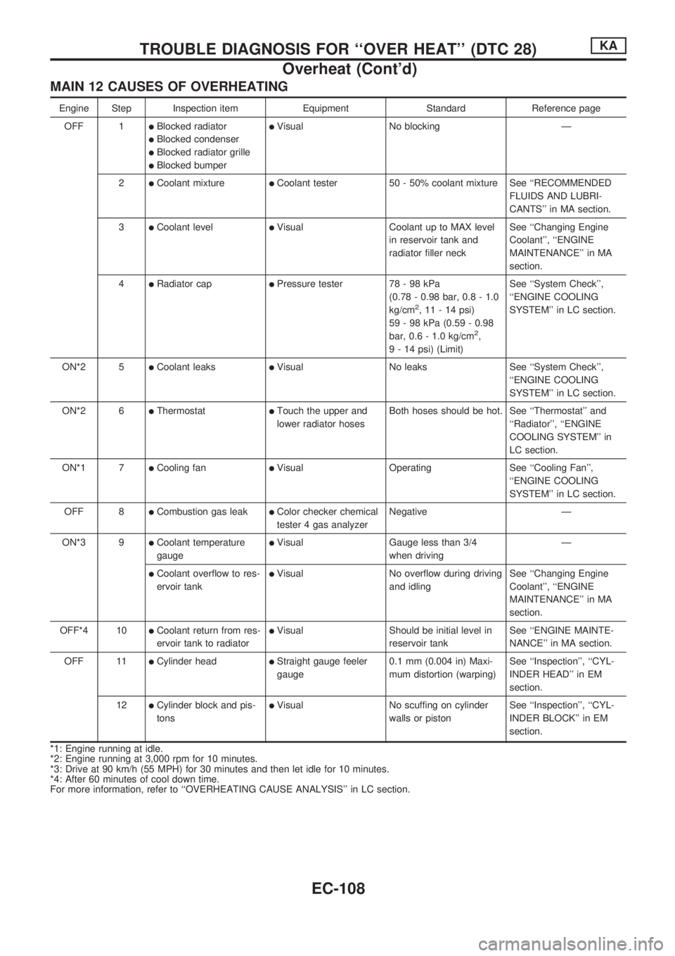
MAIN 12 CAUSES OF OVERHEATING
Engine Step Inspection item Equipment Standard Reference page
OFF 1
lBlocked radiator
lBlocked condenser
lBlocked radiator grille
lBlocked bumper
lVisual No blocking Ð
2
lCoolant mixturelCoolant tester 50 - 50% coolant mixture See ``RECOMMENDED
FLUIDS AND LUBRI-
CANTS'' in MA section.
3
lCoolant levellVisual Coolant up to MAX level
in reservoir tank and
radiator filler neckSee ``Changing Engine
Coolant'', ``ENGINE
MAINTENANCE'' in MA
section.
4
lRadiator caplPressure tester 78 - 98 kPa
(0.78 - 0.98 bar, 0.8 - 1.0
kg/cm
2, 11 - 14 psi)
59 - 98 kPa (0.59 - 0.98
bar, 0.6 - 1.0 kg/cm
2,
9 - 14 psi) (Limit)See ``System Check'',
``ENGINE COOLING
SYSTEM'' in LC section.
ON*2 5
lCoolant leakslVisual No leaks See ``System Check'',
``ENGINE COOLING
SYSTEM'' in LC section.
ON*2 6
lThermostatlTouch the upper and
lower radiator hosesBoth hoses should be hot. See ``Thermostat'' and
``Radiator'', ``ENGINE
COOLING SYSTEM'' in
LC section.
ON*1 7
lCooling fanlVisual Operating See ``Cooling Fan'',
``ENGINE COOLING
SYSTEM'' in LC section.
OFF 8
lCombustion gas leaklColor checker chemical
tester 4 gas analyzerNegative Ð
ON*3 9
lCoolant temperature
gaugelVisual Gauge less than 3/4
when drivingÐ
lCoolant overflow to res-
ervoir tanklVisual No overflow during driving
and idlingSee ``Changing Engine
Coolant'', ``ENGINE
MAINTENANCE'' in MA
section.
OFF*4 10
lCoolant return from res-
ervoir tank to radiatorlVisual Should be initial level in
reservoir tankSee ``ENGINE MAINTE-
NANCE'' in MA section.
OFF 11
lCylinder headlStraight gauge feeler
gauge0.1 mm (0.004 in) Maxi-
mum distortion (warping)See ``Inspection'', ``CYL-
INDER HEAD'' in EM
section.
12
lCylinder block and pis-
tonslVisual No scuffing on cylinder
walls or pistonSee ``Inspection'', ``CYL-
INDER BLOCK'' in EM
section.
*1: Engine running at idle.
*2: Engine running at 3,000 rpm for 10 minutes.
*3: Drive at 90 km/h (55 MPH) for 30 minutes and then let idle for 10 minutes.
*4: After 60 minutes of cool down time.
For more information, refer to ``OVERHEATING CAUSE ANALYSIS'' in LC section.
TROUBLE DIAGNOSIS FOR ``OVER HEAT'' (DTC 28)KA
Overheat (Cont'd)
EC-108
Page 898 of 1659
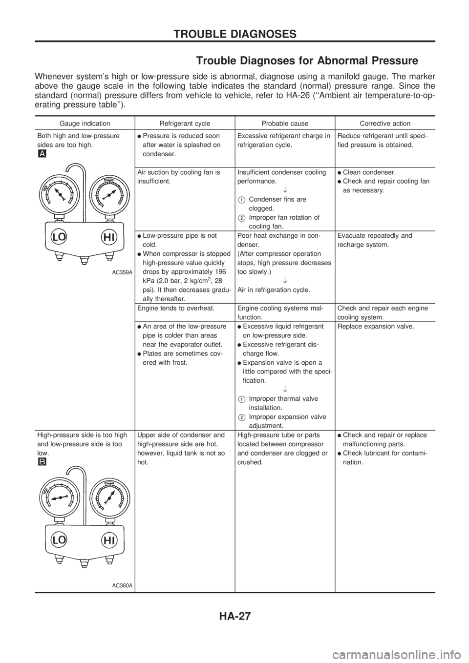
Trouble Diagnoses for Abnormal Pressure
Whenever system's high or low-pressure side is abnormal, diagnose using a manifold gauge. The marker
above the gauge scale in the following table indicates the standard (normal) pressure range. Since the
standard (normal) pressure differs from vehicle to vehicle, refer to HA-26 (``Ambient air temperature-to-op-
erating pressure table'').
Gauge indication Refrigerant cycle Probable cause Corrective action
Both high and low-pressure
sides are too high.
AC359A
lPressure is reduced soon
after water is splashed on
condenser.Excessive refrigerant charge in
refrigeration cycle.Reduce refrigerant until speci-
fied pressure is obtained.
Air suction by cooling fan is
insufficient.Insufficient condenser cooling
performance.
¯
V1Condenser fins are
clogged.
V2Improper fan rotation of
cooling fan.
lClean condenser.
lCheck and repair cooling fan
as necessary.
lLow-pressure pipe is not
cold.
lWhen compressor is stopped
high-pressure value quickly
drops by approximately 196
kPa (2.0 bar, 2 kg/cm
2,28
psi). It then decreases gradu-
ally thereafter.Poor heat exchange in con-
denser.
(After compressor operation
stops, high pressure decreases
too slowly.)
¯
Air in refrigeration cycle.Evacuate repeatedly and
recharge system.
Engine tends to overheat. Engine cooling systems mal-
function.Check and repair each engine
cooling system.
lAn area of the low-pressure
pipe is colder than areas
near the evaporator outlet.
lPlates are sometimes cov-
ered with frost.
lExcessive liquid refrigerant
on low-pressure side.
lExcessive refrigerant dis-
charge flow.
lExpansion valve is open a
little compared with the speci-
fication.
¯
V1Improper thermal valve
installation.
V2Improper expansion valve
adjustment.Replace expansion valve.
High-pressure side is too high
and low-pressure side is too
low.
AC360A
Upper side of condenser and
high-pressure side are hot,
however, liquid tank is not so
hot.High-pressure tube or parts
located between compressor
and condenser are clogged or
crushed.lCheck and repair or replace
malfunctioning parts.
lCheck lubricant for contami-
nation.
TROUBLE DIAGNOSES
HA-27
Page 939 of 1659
ENGINE LUBRICATION &
COOLING SYSTEMS
SECTION
LC
CONTENTS
PRECAUTIONS AND PREPARATION..................... 1
Liquid Gasket Application Procedure .................... 1
Special Service Tools ............................................ 2
KA
ENGINE LUBRICATION SYSTEM............................ 3
Lubrication Circuit .................................................. 3
Oil Pressure Check ................................................ 4
Oil Pump ................................................................ 4
ENGINE COOLING SYSTEM.................................... 6
Cooling Circuit........................................................ 6
System Check ........................................................ 6
Water Pump ........................................................... 7
Thermostat ............................................................. 8
Radiator.................................................................. 9
Cooling Fan (Crankshaft driven).......................... 10
TD
ENGINE LUBRICATION SYSTEM.......................... 12
Lubrication Circuit ................................................ 12
Oil Pressure Check (On-vehicle service) ............ 13
Oil Pump .............................................................. 14
Oil Filter Bracket .................................................. 16
Oil Cooler ............................................................. 17Oil Jet ................................................................... 18
ENGINE COOLING SYSTEM.................................. 19
Cooling Circuit...................................................... 19
Cooling System Inspection .................................. 20
Water Pump and Cooling Fan (Camshaft
driven) .................................................................. 21
Thermostat ........................................................... 23
Radiator................................................................ 24
Refilling Engine Coolant ...................................... 24
ENGINE ROOM FAN MOTOR ELECTRICAL
CIRCUIT................................................................... 25
Wiring Diagram .................................................... 25
Cooling Fan (Motor driven) .................................. 26
Electrical Components Inspection ....................... 26
ENGINE COOLING SYSTEM.................................. 28
Radiator (Aluminum type) .................................... 28
Overheating Cause Analysis ............................... 31
SERVICE DATA AND SPECIFICATIONS (SDS)... 32
Engine Lubrication System (KA).......................... 32
Engine Cooling System (KA) ............................... 32
Engine Lubrication System (TD).......................... 32
Engine Cooling System (TD) ............................... 32
LC
Page 970 of 1659
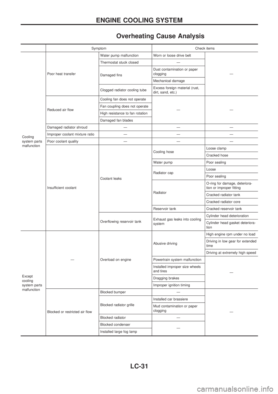
Overheating Cause Analysis
Symptom Check items
Cooling
system parts
malfunctionPoor heat transferWater pump malfunction Worn or loose drive belt
Ð Thermostat stuck closed Ð
Damaged finsDust contamination or paper
clogging
Mechanical damage
Clogged radiator cooling tubeExcess foreign material (rust,
dirt, sand, etc.)
Reduced air flowCooling fan does not operate
ÐÐ Fan coupling does not operate
High resistance to fan rotation
Damaged fan blades
Damaged radiator shroud Ð Ð Ð
Improper coolant mixture ratio Ð Ð Ð
Poor coolant quality Ð Ð Ð
Insufficient coolantCoolant leaksCooling hoseLoose clamp
Cracked hose
Water pump Poor sealing
Radiator capLoose
Poor sealing
RadiatorO-ring for damage, deteriora-
tion or improper fitting
Cracked radiator tank
Cracked radiator core
Reservoir tank Cracked reservoir tank
Overflowing reservoir tankExhaust gas leaks into cooling
systemCylinder head deterioration
Cylinder head gasket deteriora-
tion
Except
cooling
system parts
malfunctionÐ Overload on engineAbusive drivingHigh engine rpm under no load
Driving in low gear for extended
time
Driving at extremely high speed
Powertrain system malfunction
Ð Installed improper size wheels
and tires
Dragging brakes
Improper ignition timing
Blocked or restricted air flowBlocked bumper Ð
Ð Blocked radiator grilleInstalled car brassiere
Mud contamination or paper
clogging
Blocked radiator Ð
Blocked condenser
Ð
Installed large fog lamp
ENGINE COOLING SYSTEM
LC-31
Page 999 of 1659
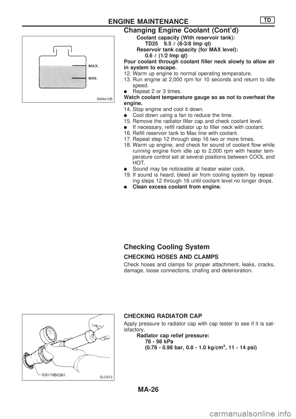
Coolant capacity (With reservoir tank):
TD25 9.5!(8-3/8 Imp qt)
Reservoir tank capacity (for MAX level):
0.6!(1/2 Imp qt)
Pour coolant through coolant filler neck slowly to allow air
in system to escape.
12. Warm up engine to normal operating temperature.
13. Run engine at 2,000 rpm for 10 seconds and return to idle
speed.
lRepeat 2 or 3 times.
Watch coolant temperature gauge so as not to overheat the
engine.
14. Stop engine and cool it down.
lCool down using a fan to reduce the time.
15. Remove the radiator filler cap and check coolant level.
lIf necessary, refill radiator up to filler neck with coolant.
16. Refill reservoir tank to Max line with coolant.
17. Repeat step 12 through step 16 two or more times.
18. Warm up engine, and check for sound of coolant flow while
running engine from idle up to 2,000 rpm with heater tem-
perature control set at several positions between COOL and
HOT.
lSound may be noticeable at heater water cock.
19. If sound is heard, bleed air from cooling system by repeat-
ing steps 12 through 16 until coolant level no longer drops.
lClean excess coolant from engine.
Checking Cooling System
CHECKING HOSES AND CLAMPS
Check hoses and clamps for proper attachment, leaks, cracks,
damage, loose connections, chafing and deterioration.
CHECKING RADIATOR CAP
Apply pressure to radiator cap with cap tester to see if it is sat-
isfactory.
Radiator cap relief pressure:
78-98kPa
(0.78 - 0.98 bar, 0.8 - 1.0 kg/cm
2, 11 - 14 psi)
SMA412B
SLC613
ENGINE MAINTENANCETD
Changing Engine Coolant (Cont'd)
MA-26