display NISSAN PICK-UP 1998 Repair Manual
[x] Cancel search | Manufacturer: NISSAN, Model Year: 1998, Model line: PICK-UP, Model: NISSAN PICK-UP 1998Pages: 1659, PDF Size: 53.39 MB
Page 60 of 1659
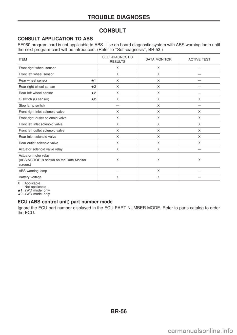
CONSULT
CONSULT APPLICATION TO ABS
EE960 program card is not applicable to ABS. Use on board diagnostic system with ABS warning lamp until
the next program card will be introduced. (Refer to ``Self-diagnosis'', BR-53.)
ITEMSELF-DIAGNOSTIC
RESULTSDATA MONITOR ACTIVE TEST
Front right wheel sensor X X Ð
Front left wheel sensor X X Ð
Rear wheel sensor.1X X Ð
Rear right wheel sensor.2X X Ð
Rear left wheel sensor.2X X Ð
G switch (G sensor).2XXX
Stop lamp switch Ð X Ð
Front right inlet solenoid valve X X X
Front right outlet solenoid valve X X X
Front left inlet solenoid valve X X X
Front left outlet solenoid valve X X X
Rear inlet solenoid valve X X X
Rear outlet solenoid valve X X X
Actuator solenoid valve relay X X Ð
Actuator motor relay
(ABS MOTOR is shown on the Data Monitor
screen.)XXX
ABS warning lamp Ð X Ð
Battery voltage X X Ð
X : Applicable
Ð : Not applicable
.1: 2WD model only
.2: 4WD model only
ECU (ABS control unit) part number mode
Ignore the ECU part number displayed in the ECU PART NUMBER MODE. Refer to parts catalog to order
the ECU.
TROUBLE DIAGNOSES
BR-56
Page 158 of 1659
Precautions
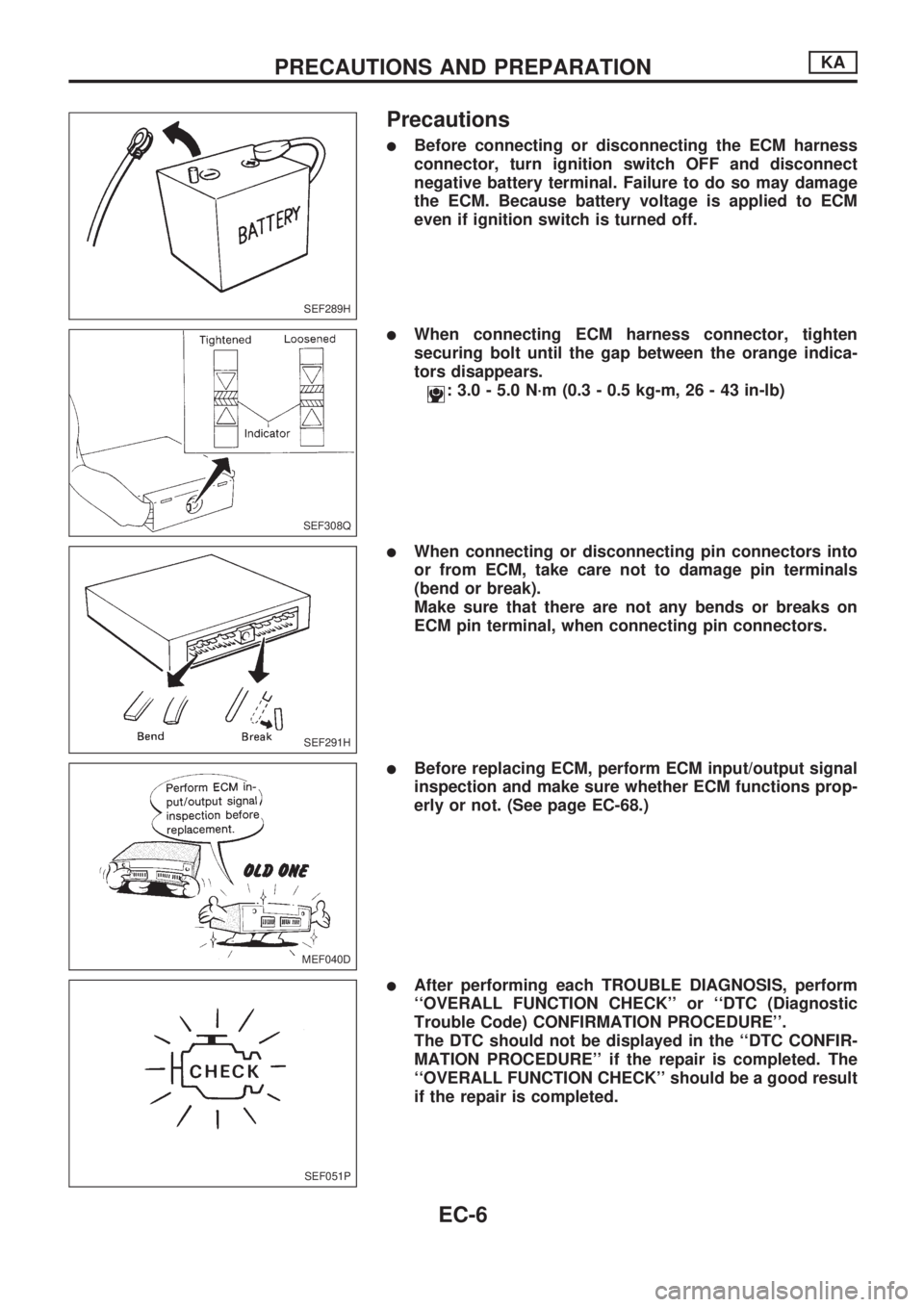
lBefore connecting or disconnecting the ECM harness
connector, turn ignition switch OFF and disconnect
negative battery terminal. Failure to do so may damage
the ECM. Because battery voltage is applied to ECM
even if ignition switch is turned off.
lWhen connecting ECM harness connector, tighten
securing bolt until the gap between the orange indica-
tors disappears.
: 3.0 - 5.0 N´m (0.3 - 0.5 kg-m, 26 - 43 in-lb)
lWhen connecting or disconnecting pin connectors into
or from ECM, take care not to damage pin terminals
(bend or break).
Make sure that there are not any bends or breaks on
ECM pin terminal, when connecting pin connectors.
lBefore replacing ECM, perform ECM input/output signal
inspection and make sure whether ECM functions prop-
erly or not. (See page EC-68.)
lAfter performing each TROUBLE DIAGNOSIS, perform
``OVERALL FUNCTION CHECK'' or ``DTC (Diagnostic
Trouble Code) CONFIRMATION PROCEDURE''.
The DTC should not be displayed in the ``DTC CONFIR-
MATION PROCEDURE'' if the repair is completed. The
``OVERALL FUNCTION CHECK'' should be a good result
if the repair is completed.
SEF289H
SEF308Q
SEF291H
MEF040D
SEF051P
PRECAUTIONS AND PREPARATIONKA
EC-6
Page 188 of 1659
Introduction
The ECM (ECCS control module) has an on board diagnostic system, which detects malfunctions related to
engine sensors or actuators. Self-diagnosis items are listed in ``DIAGNOSTIC TROUBLE CODE INDEX'',
EC-1.
The malfunction indicator lamp (MIL) on the instrument panel lights up when a malfunction is detected, or
when the ECM enters fail-safe mode (Refer to EC-61).
Diagnostic Trouble Code (DTC)
HOW TO CONFIRM MALFUNCTION ITEMS
Malfunction items can be confirmed by the following methods.
1. The number of blinks of the malfunction indicator lamp in the Diagnostic Test Mode II (Self- Diag-
nostic Results) indicates the DTC. Examples: 11, 21 etc.
2. CONSULT displays the malfunctioning component or system in ``SELF DIAGNOSTIC RESULTS''
mode.
lOutput of a DTC indicates a malfunction. However, Mode II does not indicate whether the mal-
function is still occurring or has occurred in the past and has returned to normal.
CONSULT can identify malfunction status as shown below. Therefore, using CONSULT (if avail-
able) is recommended.
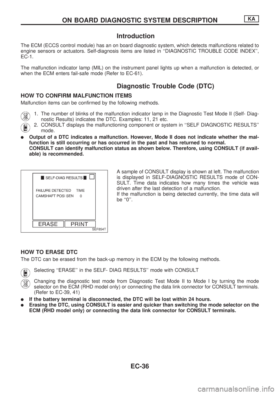
A sample of CONSULT display is shown at left. The malfunction
is displayed in SELF-DIAGNOSTIC RESULTS mode of CON-
SULT. Time data indicates how many times the vehicle was
driven after the last detection of a malfunction.
If the malfunction is being detected currently, the time data will
be ``0''.
HOW TO ERASE DTC
The DTC can be erased from the back-up memory in the ECM by the following methods.
Selecting ``ERASE'' in the SELF- DIAG RESULTS'' mode with CONSULT
Changing the diagnostic test mode from Diagnostic Test Mode II to Mode I by turning the mode
selector on the ECM (RHD model only) or connecting the data link connector for CONSULT terminals.
(Refer to EC-39, 41)
lIf the battery terminal is disconnected, the DTC will be lost within 24 hours.
lErasing the DTC, using CONSULT is easier and quicker than switching the mode selector on the
ECM (RHD model only) or connecting the data link connector for CONSULT terminals.
SEF854T
ON BOARD DIAGNOSTIC SYSTEM DESCRIPTIONKA
EC-36
Page 195 of 1659
DIAGNOSTIC TEST MODE IÐBULB CHECK
In this mode, the MALFUNCTION INDICATOR LAMP on the instrument panel should stay ON. If it remains
OFF, check the bulb. (See the WARNING LAMPS AND CHIME in the EL section. Or see EC-173, 174.)
DIAGNOSTIC TEST MODE IÐMALFUNCTION WARNING
MALFUNCTION
INDICATOR LAMPCondition
ON When the malfunction is detected (Refer to EC-1.) or the ECM's CPU is malfunctioning.
OFF No malfunction
lThese Diagnostic Trouble Code Numbers are clarified in Diagnostic Test Mode II (SELF-DIAGNOSTIC
RESULTS).
DIAGNOSTIC TEST MODE IIÐSELF-DIAGNOSTIC RESULTS
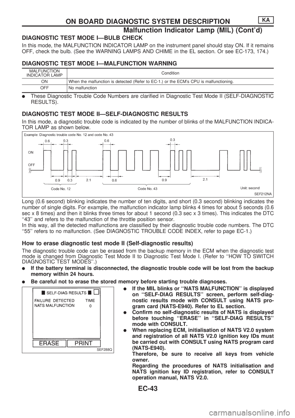
In this mode, a diagnostic trouble code is indicated by the number of blinks of the MALFUNCTION INDICA-
TOR LAMP as shown below.
Long (0.6 second) blinking indicates the number of ten digits, and short (0.3 second) blinking indicates the
number of single digits. For example, the malfunction indicator lamp blinks 4 times for about 5 seconds (0.6
sec x 8 times) and then it blinks three times for about 1 second (0.3 sec x 3 times). This indicates the DTC
``43'' and refers to the malfunction of the throttle position sensor.
In this way, all the detected malfunctions are classified by their diagnostic trouble code numbers. The DTC
``55'' refers to no malfunction. (See DIAGNOSTIC TROUBLE CODE INDEX, refer to page EC-1.)
How to erase diagnostic test mode II (Self-diagnostic results)
The diagnostic trouble code can be erased from the backup memory in the ECM when the diagnostic test
mode is changed from Diagnostic Test Mode II to Diagnostic Test Mode I. (Refer to ``HOW TO SWITCH
DIAGNOSTIC TEST MODES''.)
lIf the battery terminal is disconnected, the diagnostic trouble code will be lost from the backup
memory within 24 hours.
lBe careful not to erase the stored memory before starting trouble diagnoses.
lIf the MIL blinks or ``NATS MALFUNCTION'' is displayed
on ``SELF-DIAG RESULTS'' screen, perform self-diag-
nostic results mode with CONSULT using NATS pro-
gram card (NATS-E940). Refer to EL section.
lConfirm no self-diagnostic results of NATS is displayed
before touching ``ERASE'' in ``SELF-DIAG RESULTS''
mode with CONSULT.
lWhen replacing ECM, initialisation of NATS V2.0 system
and registration of all NATS V2.0 ignition key IDs must
be carried out with CONSULT using NATS program card
(NATS-E940).
Therefore, be sure to receive all keys from vehicle
owner.
Regarding the procedures of NATS initialisation and
NATS ignition key ID registration, refer to CONSULT
operation manual, NATS V2.0.
SEF212NA
SEF288Q
ON BOARD DIAGNOSTIC SYSTEM DESCRIPTIONKA
Malfunction Indicator Lamp (MIL) (Cont'd)
EC-43
Page 196 of 1659
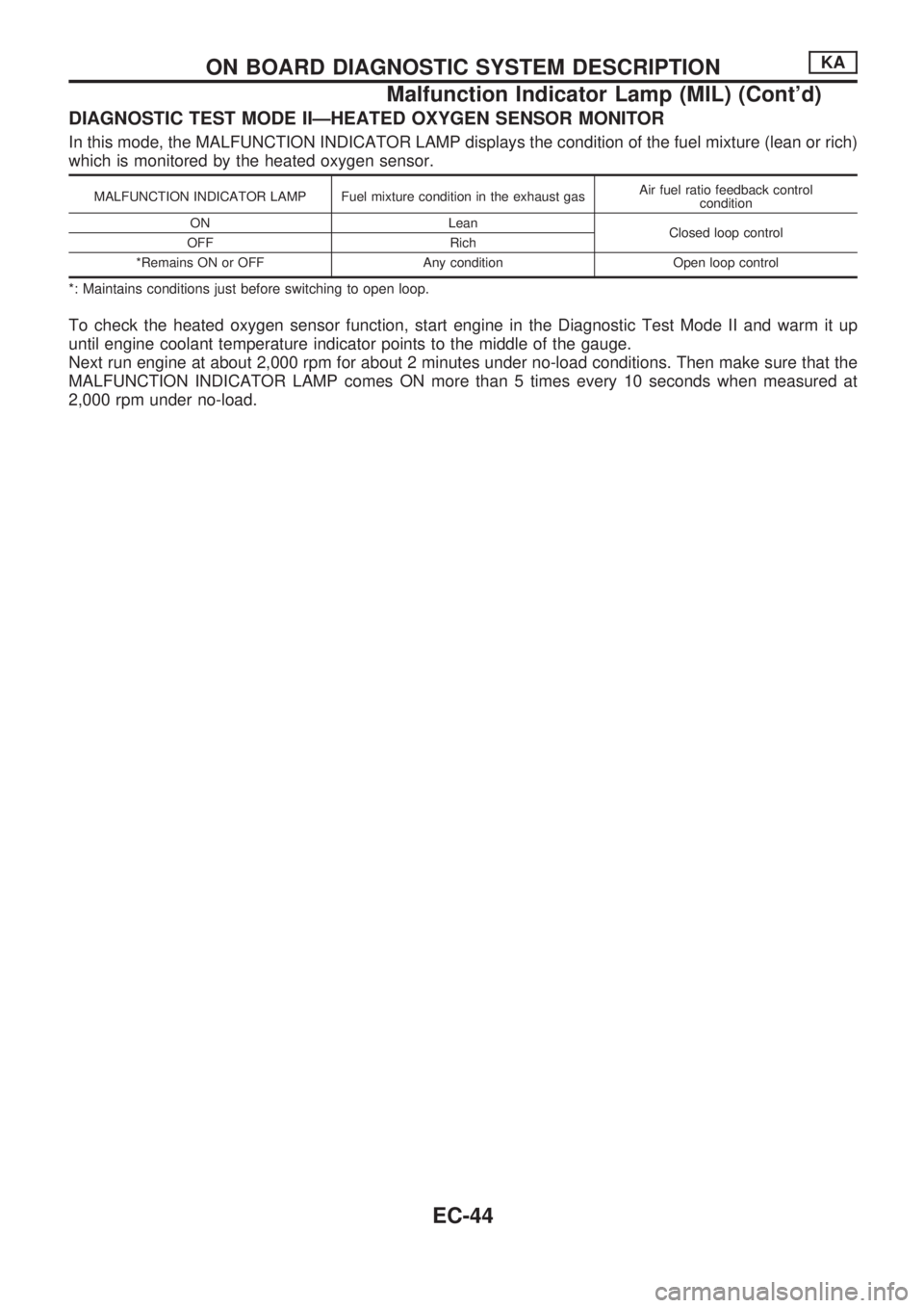
DIAGNOSTIC TEST MODE IIÐHEATED OXYGEN SENSOR MONITOR
In this mode, the MALFUNCTION INDICATOR LAMP displays the condition of the fuel mixture (lean or rich)
which is monitored by the heated oxygen sensor.
MALFUNCTION INDICATOR LAMP Fuel mixture condition in the exhaust gasAir fuel ratio feedback control
condition
ON Lean
Closed loop control
OFF Rich
*Remains ON or OFF Any condition Open loop control
*: Maintains conditions just before switching to open loop.
To check the heated oxygen sensor function, start engine in the Diagnostic Test Mode II and warm it up
until engine coolant temperature indicator points to the middle of the gauge.
Next run engine at about 2,000 rpm for about 2 minutes under no-load conditions. Then make sure that the
MALFUNCTION INDICATOR LAMP comes ON more than 5 times every 10 seconds when measured at
2,000 rpm under no-load.
ON BOARD DIAGNOSTIC SYSTEM DESCRIPTIONKA
Malfunction Indicator Lamp (MIL) (Cont'd)
EC-44
Page 200 of 1659
![NISSAN PICK-UP 1998 Repair Manual SELF-DIAGNOSTIC MODE
Regarding items detected in ``SELF-DIAG RESULTS mode, refer to ``DIAGNOSTIC TROUBLE CODE
INDEX, EC-1.
DATA MONITOR MODE
Monitored item
[Unit]ECM
input
signalsMain
signalsDescr NISSAN PICK-UP 1998 Repair Manual SELF-DIAGNOSTIC MODE
Regarding items detected in ``SELF-DIAG RESULTS mode, refer to ``DIAGNOSTIC TROUBLE CODE
INDEX, EC-1.
DATA MONITOR MODE
Monitored item
[Unit]ECM
input
signalsMain
signalsDescr](/img/5/57374/w960_57374-199.png)
SELF-DIAGNOSTIC MODE
Regarding items detected in ``SELF-DIAG RESULTS'' mode, refer to ``DIAGNOSTIC TROUBLE CODE
INDEX'', EC-1.
DATA MONITOR MODE
Monitored item
[Unit]ECM
input
signalsMain
signalsDescription Remarks
CMPSRPM
(POS) [rpm]
jj
lIndicates the engine speed computed
from the POS signal (1É signal) of the
camshaft position sensor.
MAS AIR/FL SE [V]
jjlThe signal voltage of the mass air flow
sensor is displayed.lWhen the engine is stopped, a certain
value is indicated.
COOLAN TEMP/S
[ÉC] or [ÉF]
jj
lThe engine coolant temperature (deter-
mined by the signal voltage of the engine
coolant temperature sensor) is displayed.lWhen the engine coolant temperature
sensor is open or short-circuited, ECM
enters fail-safe mode. The engine coolant
temperature determined by the ECM is
displayed.
O2 SEN [V]
jjlThe signal voltage of the heated oxygen
sensor is displayed.lLHD models only
M/R F/C MNT
[RICH/LEAN]
jj
lDisplay of heated oxygen sensor signal
during air-fuel ratio feedback control:
RICH ... means the mixture became
``rich'', and control is being affected
toward a leaner mixture.
LEAN ... means the mixture became
``lean'', and control is being affected
toward a rich mixture.lAfter turning ON the ignition switch,
``RICH'' is displayed until air-fuel mixture
ratio feedback control begins.
lWhen the air-fuel ratio feedback is
clamped, the value just before the clamp-
ing is displayed continuously.
lLHD models only
VHCL SPEED SE
[km/h] or [mph]
jjlThe vehicle speed computed from the
vehicle speed sensor signal is displayed.
BATTERY VOLT [V]
jjlThe power supply voltage of ECM is dis-
played.
THRTL POS SEN [V]
jjlThe throttle position sensor signal volt-
age is displayed.
INT/A TEMP SE
[ÉC] or [ÉF]
j
lThe intake air temperature (determined
by the signal voltage of the intake air
temperature sensor) is indicated.
START SIGNAL
[ON/OFF]
jjlIndicates [ON/OFF] condition from the
starter signal.lAfter starting the engine, [OFF] is
displayed regardless of the starter signal.
CLSD THL/POSI
[ON/OFF]
jj
lIndicates [ON/OFF] condition from the
throttle position sensor signal.
AIR COND SIG
[ON/OFF]
jj
lIndicates [ON/OFF] condition of the air
conditioner switch as determined by the
air conditioner signal.
P/N POSI SW
[ON/OFF]
jj
lIndicates [ON/OFF] condition from the
park/neutral position switch signal.
PW/ST SIGNAL
[ON/OFF]
jj
l[ON/OFF] condition of the power steering
oil pressure switch determined by the
power steering oil pressure signal is indi-
cated.
NOTE:
Any monitored item that does not match the vehicle being diagnosed is deleted from the display automatically.
ON BOARD DIAGNOSTIC SYSTEM DESCRIPTIONKA
CONSULT (Cont'd)
EC-48
Page 201 of 1659
![NISSAN PICK-UP 1998 Repair Manual Monitored item
[Unit]ECM
input
signalsMain
signalsDescription Remarks
INJ PULSE [msec]
j
lIndicates the actual fuel injection pulse
width compensated by ECM according to
the input signals.lWhen the en NISSAN PICK-UP 1998 Repair Manual Monitored item
[Unit]ECM
input
signalsMain
signalsDescription Remarks
INJ PULSE [msec]
j
lIndicates the actual fuel injection pulse
width compensated by ECM according to
the input signals.lWhen the en](/img/5/57374/w960_57374-200.png)
Monitored item
[Unit]ECM
input
signalsMain
signalsDescription Remarks
INJ PULSE [msec]
j
lIndicates the actual fuel injection pulse
width compensated by ECM according to
the input signals.lWhen the engine is stopped, a certain
computed value is indicated.
IGN TIMING [BTDC]
j
lIndicates the ignition timing computed by
ECM according to the input signals.lWhen the engine is stopped, a certain
value is indicated.
IACV-AAC/V [%]
j
lIndicates the idle air control valve (AAC
valve) control value computed by ECM
according to the input signals.
A/F ALPHA [%]
j
lThe mean value of the air-fuel ratio feed-
back correction factor per cycle is indi-
cated.lWhen the engine is stopped, a certain
value is indicated.
lThis data also includes the data for the
air-fuel ratio learning control.
AIR COND RLY
[ON/OFF]
j
lThe air conditioner relay control condition
(determined by ECM according to the
input signal) is indicated.
FUEL PUMP RLY
[ON/OFF]
j
lIndicates the fuel pump relay control con-
dition determined by ECM according to
the input signals.
SWRL CONT S/V
[ON/OFF]
j
lThe control condition of the swirl control
valve control solenoid valve (determined
by the ECM according to the input signal)
is indicated.
ON ... Swirl control valve is closed
OFF ... Swirl control valve is open
EGRC SOL/V
(EVAP canister purge
control solenoid
valve) [ON/OFF]
j
lThe control condition of the EVAP canis-
ter purge control solenoid valve (deter-
mined by ECM according to the input
signal) is indicated.
ON ... EVAP canister purge control is not
operating
OFF ... EVAP canister purge control is
operational.
VOLTAGE
[V]
lVoltage measured by the voltage probe.
PULSE
[msec] or [Hz] or [%]
lPulse width, frequency or duty cycle
measured by the pulse probe.lOnly ``#'' is displayed if item is unable to
be measured.
lFigures with ``#''s are temporary ones.
They are the same figures as an actual
piece of data which was just previously
measured.
ON BOARD DIAGNOSTIC SYSTEM DESCRIPTIONKA
CONSULT (Cont'd)
EC-49
Page 203 of 1659
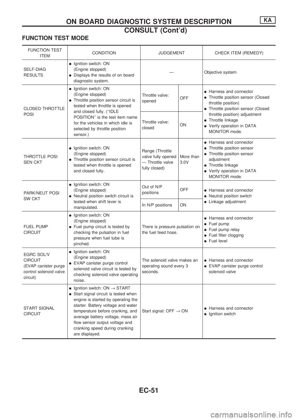
FUNCTION TEST MODE
FUNCTION TEST
ITEMCONDITION JUDGEMENT CHECK ITEM (REMEDY)
SELF-DIAG
RESULTS
lIgnition switch: ON
(Engine stopped)
lDisplays the results of on board
diagnostic system.Ð Objective system
CLOSED THROTTLE
POSI
lIgnition switch: ON
(Engine stopped)
lThrottle position sensor circuit is
tested when throttle is opened
and closed fully. (``IDLE
POSITION'' is the test item name
for the vehicles in which idle is
selected by throttle position
sensor.)Throttle valve:
openedOFF
lHarness and connector
lThrottle position sensor (Closed
throttle position)
lThrottle position sensor (Closed
throttle position) adjustment
lThrottle linkage
lVerify operation in DATA
MONITOR mode. Throttle valve:
closedON
THROTTLE POSI
SEN CKT
lIgnition switch: ON
(Engine stopped)
lThrottle position sensor circuit is
tested when throttle is opened
and closed fully.Range (Throttle
valve fully opened
Ð Throttle valve
fully closed)More than
3.0V
lHarness and connector
lThrottle position sensor
lThrottle position sensor
adjustment
lThrottle linkage
lVerify operation in DATA
MONITOR mode.
PARK/NEUT POSI
SW CKT
lIgnition switch: ON
(Engine stopped)
lNeutral position switch circuit is
tested when shift lever is
manipulated.Out of N/P
positionsOFF
lHarness and connector
lNeutral position switch
lLinkage adjustment
In N/P positions ON
FUEL PUMP
CIRCUIT
lIgnition switch: ON
(Engine stopped)
lFuel pump circuit is tested by
checking the pulsation in fuel
pressure when fuel tube is
pinched.There is pressure pulsation on
the fuel feed hose.
lHarness and connector
lFuel pump
lFuel pump relay
lFuel filter clogging
lFuel level
EGRC SOL/V
CIRCUIT
(EVAP canister purge
control solenoid valve
circuit)
lIgnition switch: ON
(Engine stopped)
lEVAP canister purge control
solenoid valve circuit is tested by
checking solenoid valve operating
noise.The solenoid valve makes an
operating sound every 3
seconds.lHarness and connector
lEVAP canister purge control
solenoid valve
START SIGNAL
CIRCUIT
lIgnition switch: ON®START
lStart signal circuit is tested when
engine is started by operating the
starter. Battery voltage and water
temperature before cranking, and
average battery voltage, mass air
flow sensor output voltage and
cranking speed during cranking
are displayed.Start signal: OFF®ON
lHarness and connector
lIgnition switch
ON BOARD DIAGNOSTIC SYSTEM DESCRIPTIONKA
CONSULT (Cont'd)
EC-51
Page 204 of 1659
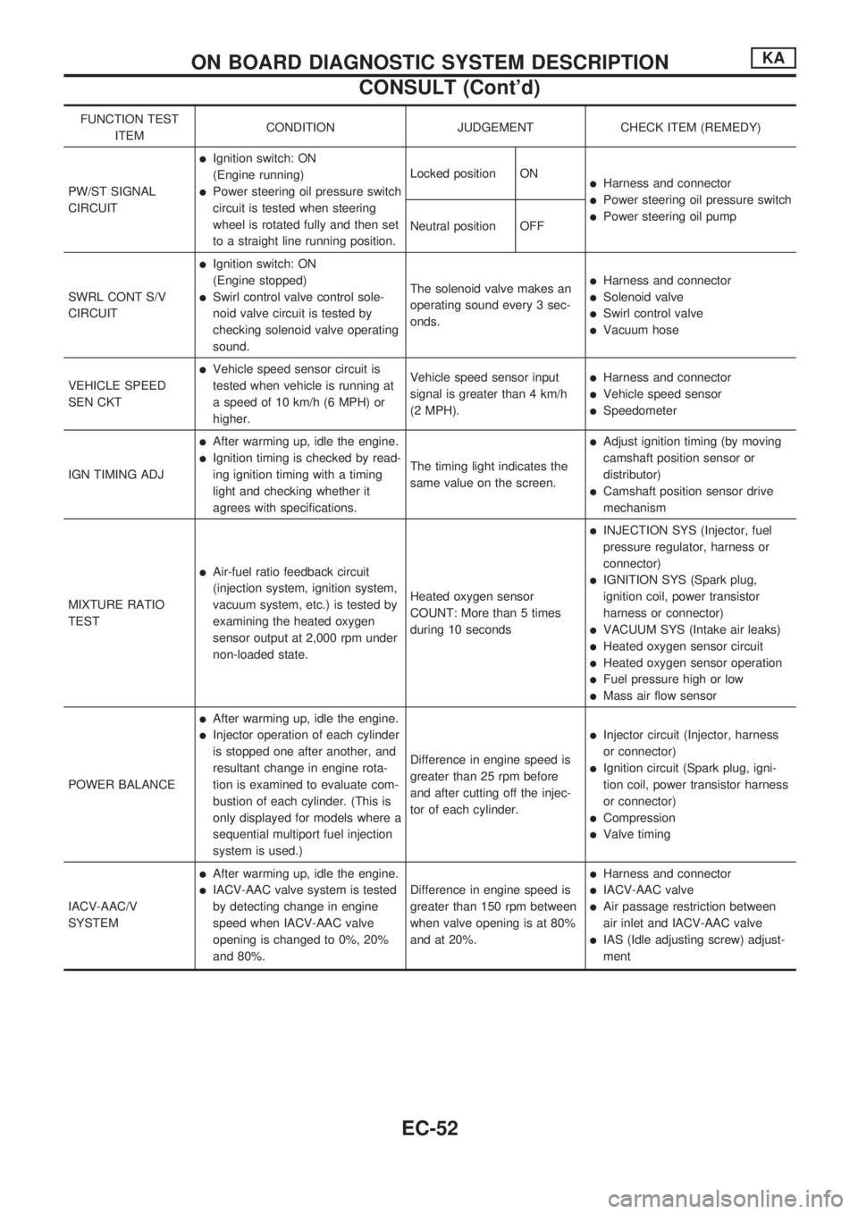
FUNCTION TEST
ITEMCONDITION JUDGEMENT CHECK ITEM (REMEDY)
PW/ST SIGNAL
CIRCUIT
lIgnition switch: ON
(Engine running)
lPower steering oil pressure switch
circuit is tested when steering
wheel is rotated fully and then set
to a straight line running position.Locked position ONlHarness and connector
lPower steering oil pressure switch
lPower steering oil pump
Neutral position OFF
SWRL CONT S/V
CIRCUIT
lIgnition switch: ON
(Engine stopped)
lSwirl control valve control sole-
noid valve circuit is tested by
checking solenoid valve operating
sound.The solenoid valve makes an
operating sound every 3 sec-
onds.
lHarness and connector
lSolenoid valve
lSwirl control valve
lVacuum hose
VEHICLE SPEED
SEN CKT
lVehicle speed sensor circuit is
tested when vehicle is running at
a speed of 10 km/h (6 MPH) or
higher.Vehicle speed sensor input
signal is greater than 4 km/h
(2 MPH).lHarness and connector
lVehicle speed sensor
lSpeedometer
IGN TIMING ADJ
lAfter warming up, idle the engine.
lIgnition timing is checked by read-
ing ignition timing with a timing
light and checking whether it
agrees with specifications.The timing light indicates the
same value on the screen.
lAdjust ignition timing (by moving
camshaft position sensor or
distributor)
lCamshaft position sensor drive
mechanism
MIXTURE RATIO
TEST
lAir-fuel ratio feedback circuit
(injection system, ignition system,
vacuum system, etc.) is tested by
examining the heated oxygen
sensor output at 2,000 rpm under
non-loaded state.Heated oxygen sensor
COUNT: More than 5 times
during 10 seconds
lINJECTION SYS (Injector, fuel
pressure regulator, harness or
connector)
lIGNITION SYS (Spark plug,
ignition coil, power transistor
harness or connector)
lVACUUM SYS (Intake air leaks)
lHeated oxygen sensor circuit
lHeated oxygen sensor operation
lFuel pressure high or low
lMass air flow sensor
POWER BALANCE
lAfter warming up, idle the engine.
lInjector operation of each cylinder
is stopped one after another, and
resultant change in engine rota-
tion is examined to evaluate com-
bustion of each cylinder. (This is
only displayed for models where a
sequential multiport fuel injection
system is used.)Difference in engine speed is
greater than 25 rpm before
and after cutting off the injec-
tor of each cylinder.lInjector circuit (Injector, harness
or connector)
lIgnition circuit (Spark plug, igni-
tion coil, power transistor harness
or connector)
lCompression
lValve timing
IACV-AAC/V
SYSTEM
lAfter warming up, idle the engine.
lIACV-AAC valve system is tested
by detecting change in engine
speed when IACV-AAC valve
opening is changed to 0%, 20%
and 80%.Difference in engine speed is
greater than 150 rpm between
when valve opening is at 80%
and at 20%.
lHarness and connector
lIACV-AAC valve
lAir passage restriction between
air inlet and IACV-AAC valve
lIAS (Idle adjusting screw) adjust-
ment
ON BOARD DIAGNOSTIC SYSTEM DESCRIPTIONKA
CONSULT (Cont'd)
EC-52
Page 205 of 1659
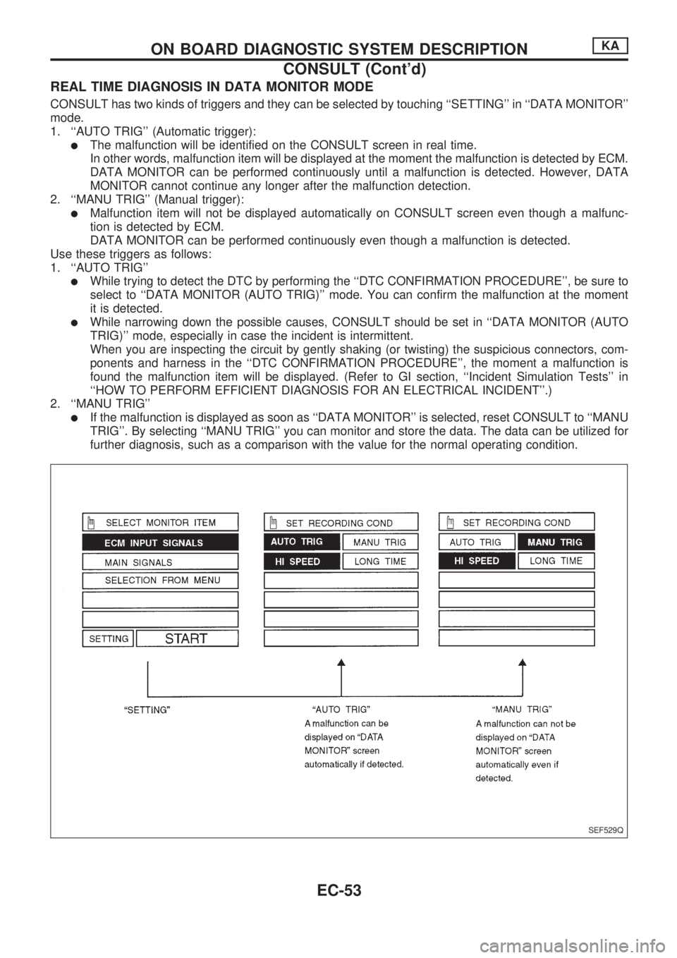
REAL TIME DIAGNOSIS IN DATA MONITOR MODE
CONSULT has two kinds of triggers and they can be selected by touching ``SETTING'' in ``DATA MONITOR''
mode.
1. ``AUTO TRIG'' (Automatic trigger):
lThe malfunction will be identified on the CONSULT screen in real time.
In other words, malfunction item will be displayed at the moment the malfunction is detected by ECM.
DATA MONITOR can be performed continuously until a malfunction is detected. However, DATA
MONITOR cannot continue any longer after the malfunction detection.
2. ``MANU TRIG'' (Manual trigger):
lMalfunction item will not be displayed automatically on CONSULT screen even though a malfunc-
tion is detected by ECM.
DATA MONITOR can be performed continuously even though a malfunction is detected.
Use these triggers as follows:
1. ``AUTO TRIG''
lWhile trying to detect the DTC by performing the ``DTC CONFIRMATION PROCEDURE'', be sure to
select to ``DATA MONITOR (AUTO TRIG)'' mode. You can confirm the malfunction at the moment
it is detected.
lWhile narrowing down the possible causes, CONSULT should be set in ``DATA MONITOR (AUTO
TRIG)'' mode, especially in case the incident is intermittent.
When you are inspecting the circuit by gently shaking (or twisting) the suspicious connectors, com-
ponents and harness in the ``DTC CONFIRMATION PROCEDURE'', the moment a malfunction is
found the malfunction item will be displayed. (Refer to GI section, ``Incident Simulation Tests'' in
``HOW TO PERFORM EFFICIENT DIAGNOSIS FOR AN ELECTRICAL INCIDENT''.)
2. ``MANU TRIG''
lIf the malfunction is displayed as soon as ``DATA MONITOR'' is selected, reset CONSULT to ``MANU
TRIG''. By selecting ``MANU TRIG'' you can monitor and store the data. The data can be utilized for
further diagnosis, such as a comparison with the value for the normal operating condition.
SEF529Q
ON BOARD DIAGNOSTIC SYSTEM DESCRIPTIONKA
CONSULT (Cont'd)
EC-53