length NISSAN PICK-UP 1998 Repair Manual
[x] Cancel search | Manufacturer: NISSAN, Model Year: 1998, Model line: PICK-UP, Model: NISSAN PICK-UP 1998Pages: 1659, PDF Size: 53.39 MB
Page 13 of 1659
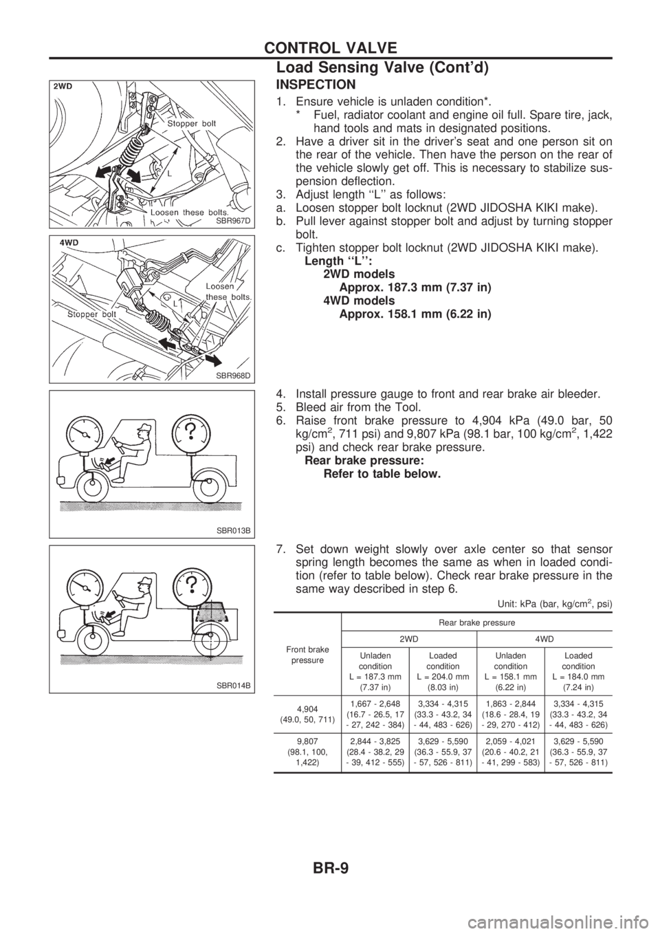
INSPECTION
1. Ensure vehicle is unladen condition*.
* Fuel, radiator coolant and engine oil full. Spare tire, jack,
hand tools and mats in designated positions.
2. Have a driver sit in the driver's seat and one person sit on
the rear of the vehicle. Then have the person on the rear of
the vehicle slowly get off. This is necessary to stabilize sus-
pension deflection.
3. Adjust length ``L'' as follows:
a. Loosen stopper bolt locknut (2WD JIDOSHA KIKI make).
b. Pull lever against stopper bolt and adjust by turning stopper
bolt.
c. Tighten stopper bolt locknut (2WD JIDOSHA KIKI make).
Length ``L'':
2WD models
Approx. 187.3 mm (7.37 in)
4WD models
Approx. 158.1 mm (6.22 in)
4. Install pressure gauge to front and rear brake air bleeder.
5. Bleed air from the Tool.
6. Raise front brake pressure to 4,904 kPa (49.0 bar, 50
kg/cm
2, 711 psi) and 9,807 kPa (98.1 bar, 100 kg/cm2, 1,422
psi) and check rear brake pressure.
Rear brake pressure:
Refer to table below.
7. Set down weight slowly over axle center so that sensor
spring length becomes the same as when in loaded condi-
tion (refer to table below). Check rear brake pressure in the
same way described in step 6.
Unit: kPa (bar, kg/cm2, psi)
Front brake
pressureRear brake pressure
2WD 4WD
Unladen
condition
L = 187.3 mm
(7.37 in)Loaded
condition
L = 204.0 mm
(8.03 in)Unladen
condition
L = 158.1 mm
(6.22 in)Loaded
condition
L = 184.0 mm
(7.24 in)
4,904
(49.0, 50, 711)1,667 - 2,648
(16.7 - 26.5, 17
- 27, 242 - 384)3,334 - 4,315
(33.3 - 43.2, 34
- 44, 483 - 626)1,863 - 2,844
(18.6 - 28.4, 19
- 29, 270 - 412)3,334 - 4,315
(33.3 - 43.2, 34
- 44, 483 - 626)
9,807
(98.1, 100,
1,422)2,844 - 3,825
(28.4 - 38.2, 29
- 39, 412 - 555)3,629 - 5,590
(36.3 - 55.9, 37
- 57, 526 - 811)2,059 - 4,021
(20.6 - 40.2, 21
- 41, 299 - 583)3,629 - 5,590
(36.3 - 55.9, 37
- 57, 526 - 811)
SBR967D
SBR968D
SBR013B
SBR014B
CONTROL VALVE
Load Sensing Valve (Cont'd)
BR-9
Page 19 of 1659
On-vehicle Service
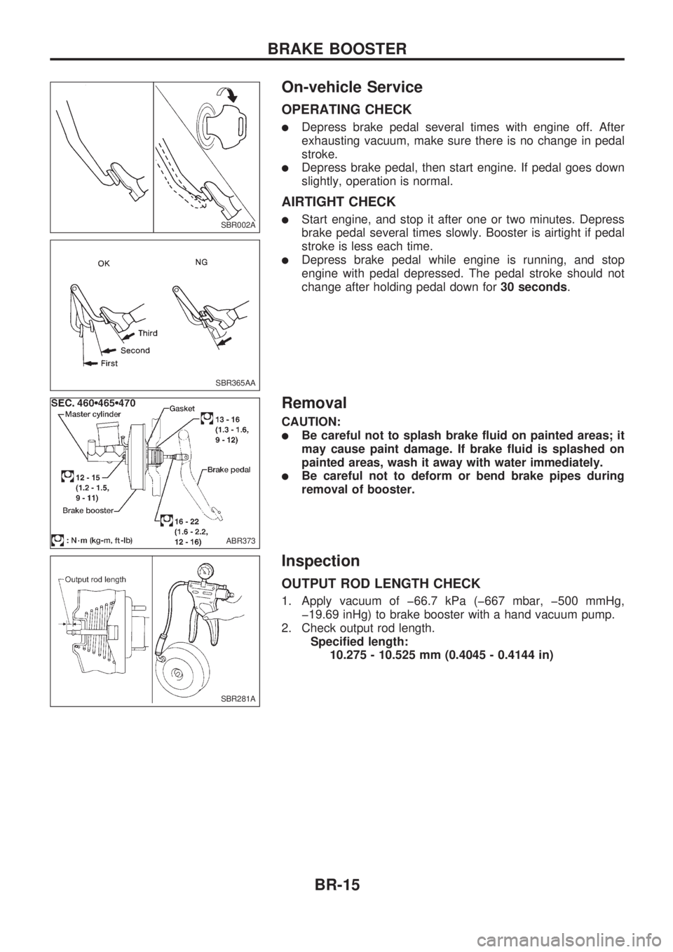
OPERATING CHECK
lDepress brake pedal several times with engine off. After
exhausting vacuum, make sure there is no change in pedal
stroke.
lDepress brake pedal, then start engine. If pedal goes down
slightly, operation is normal.
AIRTIGHT CHECK
lStart engine, and stop it after one or two minutes. Depress
brake pedal several times slowly. Booster is airtight if pedal
stroke is less each time.
lDepress brake pedal while engine is running, and stop
engine with pedal depressed. The pedal stroke should not
change after holding pedal down for30 seconds.
Removal
CAUTION:
lBe careful not to splash brake fluid on painted areas; it
may cause paint damage. If brake fluid is splashed on
painted areas, wash it away with water immediately.
lBe careful not to deform or bend brake pipes during
removal of booster.
Inspection
OUTPUT ROD LENGTH CHECK
1. Apply vacuum of þ66.7 kPa (þ667 mbar, þ500 mmHg,
þ19.69 inHg) to brake booster with a hand vacuum pump.
2. Check output rod length.
Specified length:
10.275 - 10.525 mm (0.4045 - 0.4144 in)
SBR002A
SBR365AA
ABR373
SBR281A
BRAKE BOOSTER
BR-15
Page 82 of 1659
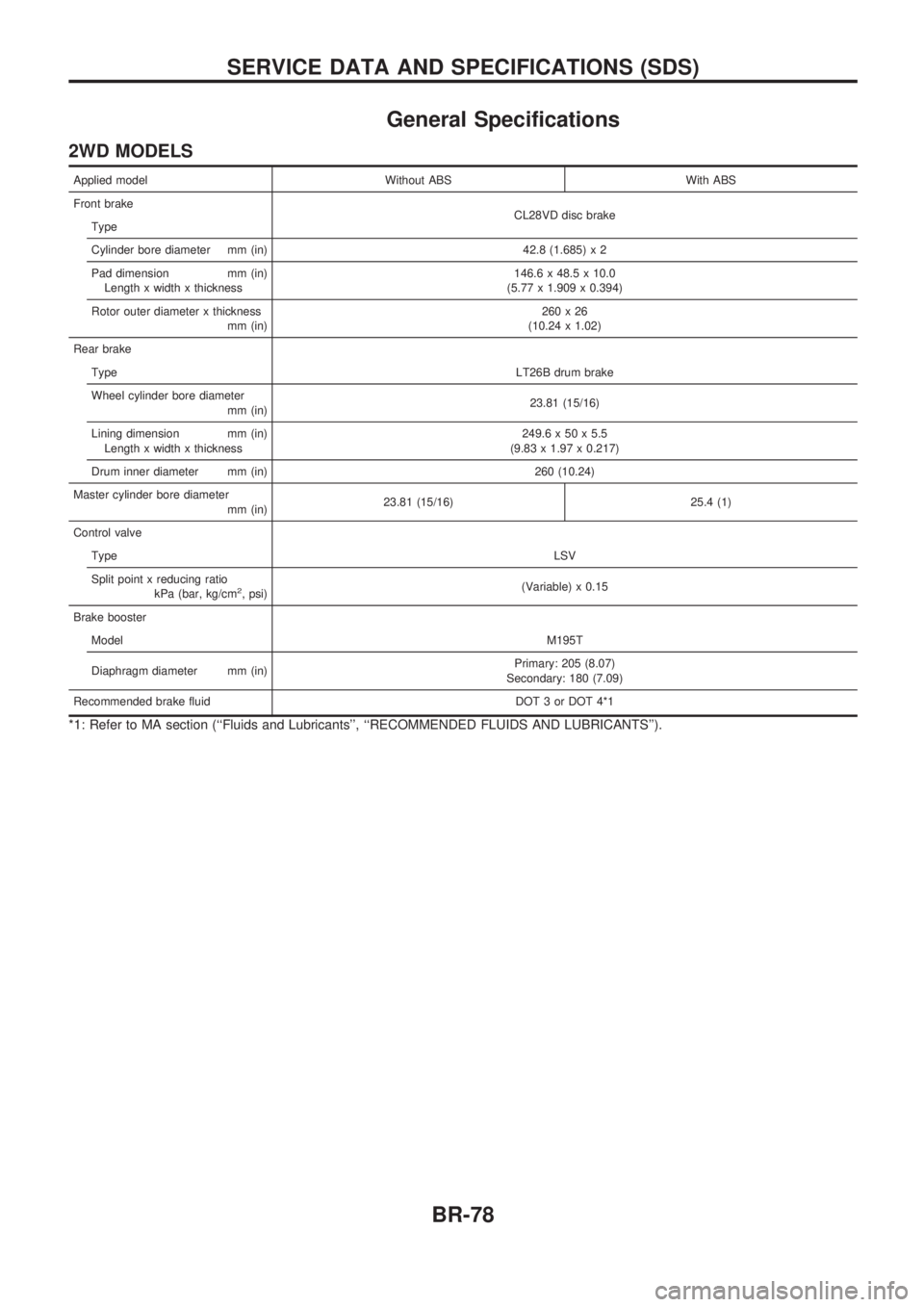
General Specifications
2WD MODELS
Applied model Without ABS With ABS
Front brake
CL28VD disc brake
Type
Cylinder bore diameter mm (in) 42.8 (1.685) x 2
Pad dimension mm (in)
Length x width x thickness146.6 x 48.5 x 10.0
(5.77 x 1.909 x 0.394)
Rotor outer diameter x thickness
mm (in)260x26
(10.24 x 1.02)
Rear brake
TypeLT26B drum brake
Wheel cylinder bore diameter
mm (in)23.81 (15/16)
Lining dimension mm (in)
Length x width x thickness249.6 x 50 x 5.5
(9.83 x 1.97 x 0.217)
Drum inner diameter mm (in) 260 (10.24)
Master cylinder bore diameter
mm (in)23.81 (15/16) 25.4 (1)
Control valve
TypeLSV
Split point x reducing ratio
kPa (bar, kg/cm
2, psi)(Variable) x 0.15
Brake booster
ModelM195T
Diaphragm diameter mm (in)Primary: 205 (8.07)
Secondary: 180 (7.09)
Recommended brake fluid DOT 3 or DOT 4*1
*1: Refer to MA section (``Fluids and Lubricants'', ``RECOMMENDED FLUIDS AND LUBRICANTS'').
SERVICE DATA AND SPECIFICATIONS (SDS)
BR-78
Page 83 of 1659
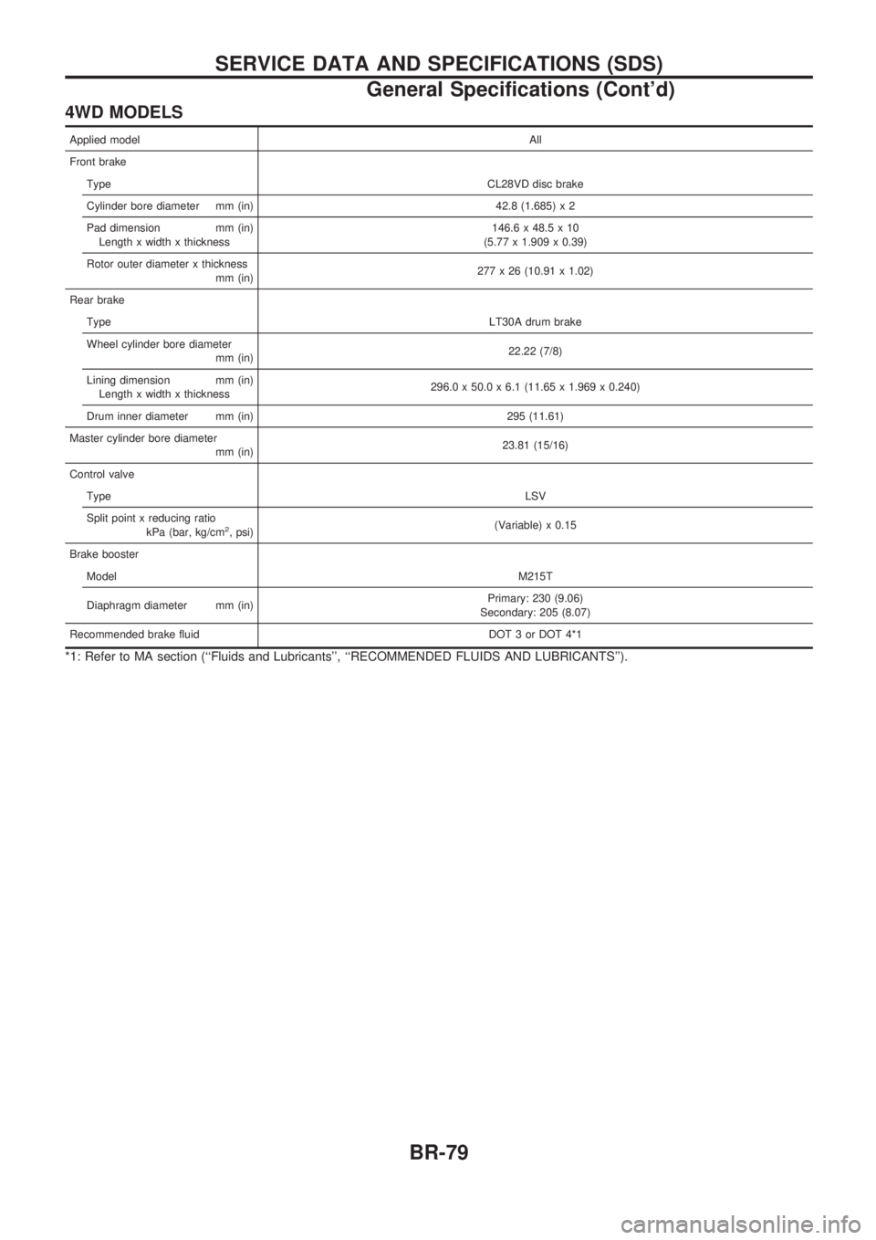
4WD MODELS
Applied modelAll
Front brake
TypeCL28VD disc brake
Cylinder bore diameter mm (in) 42.8 (1.685) x 2
Pad dimension mm (in)
Length x width x thickness146.6 x 48.5 x 10
(5.77 x 1.909 x 0.39)
Rotor outer diameter x thickness
mm (in)277 x 26 (10.91 x 1.02)
Rear brake
TypeLT30A drum brake
Wheel cylinder bore diameter
mm (in)22.22 (7/8)
Lining dimension mm (in)
Length x width x thickness296.0 x 50.0 x 6.1 (11.65 x 1.969 x 0.240)
Drum inner diameter mm (in) 295 (11.61)
Master cylinder bore diameter
mm (in)23.81 (15/16)
Control valve
TypeLSV
Split point x reducing ratio
kPa (bar, kg/cm
2, psi)(Variable) x 0.15
Brake booster
ModelM215T
Diaphragm diameter mm (in)Primary: 230 (9.06)
Secondary: 205 (8.07)
Recommended brake fluid DOT 3 or DOT 4*1
*1: Refer to MA section (``Fluids and Lubricants'', ``RECOMMENDED FLUIDS AND LUBRICANTS'').
SERVICE DATA AND SPECIFICATIONS (SDS)
General Specifications (Cont'd)
BR-79
Page 90 of 1659
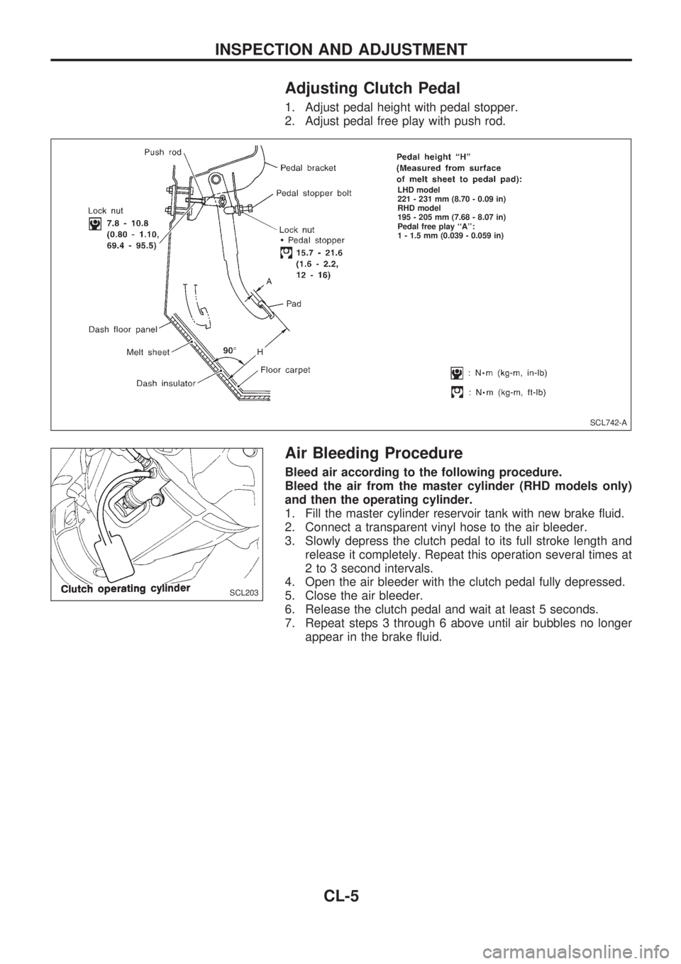
Adjusting Clutch Pedal
1. Adjust pedal height with pedal stopper.
2. Adjust pedal free play with push rod.
Air Bleeding Procedure
Bleed air according to the following procedure.
Bleed the air from the master cylinder (RHD models only)
and then the operating cylinder.
1. Fill the master cylinder reservoir tank with new brake fluid.
2. Connect a transparent vinyl hose to the air bleeder.
3. Slowly depress the clutch pedal to its full stroke length and
release it completely. Repeat this operation several times at
2 to 3 second intervals.
4. Open the air bleeder with the clutch pedal fully depressed.
5. Close the air bleeder.
6. Release the clutch pedal and wait at least 5 seconds.
7. Repeat steps 3 through 6 above until air bubbles no longer
appear in the brake fluid.
SCL742-A
.LHD model
221 - 231 mm (8.70 - 0.09 in)
RHD model
195 - 205 mm (7.68 - 8.07 in)
Pedal free play ``A'':
1 - 1.5 mm (0.039 - 0.059 in)
SCL203
INSPECTION AND ADJUSTMENT
CL-5
Page 143 of 1659
lAll dimensions indicated in figures are actual ones.
lWhen using a tracking gauge, adjust both pointers to equal length. Make sure there is no free play.
lWhen a measuring tape is used, check to be sure there is no elongation, twisting or bending.
lMeasurements should be taken at the center of the mounting holes.
lAll measurements and mounting hole diameters are expressed in millimeters (mm).
lAn asterisk (*) following the value at the measuring point indicates that the measuring point on the other
side is symmetrically the same value.
lThe coordinates of the measurement points are the distances measured from the respective dimension
lines in the directions of ``x'', ``y'' and ``z''.
Dimension lines: ``x'' line Ð Center line of vehicle
``y'' line Ð Center line of front axle (Any measurement point in front of the dimension
line refers to a minus ``Ð'' value.)
``z'' line Ð Datum line (Any measurement point under the dimension line refers to a
minus ``Ð'' value.)
2W.SB: Short wheelbase (2WD)
2W.LB
: Long wheelbase (2WD)
4W.LB
: Long wheelbase (4WD)
BODY ALIGNMENT
BT-43
Page 166 of 1659
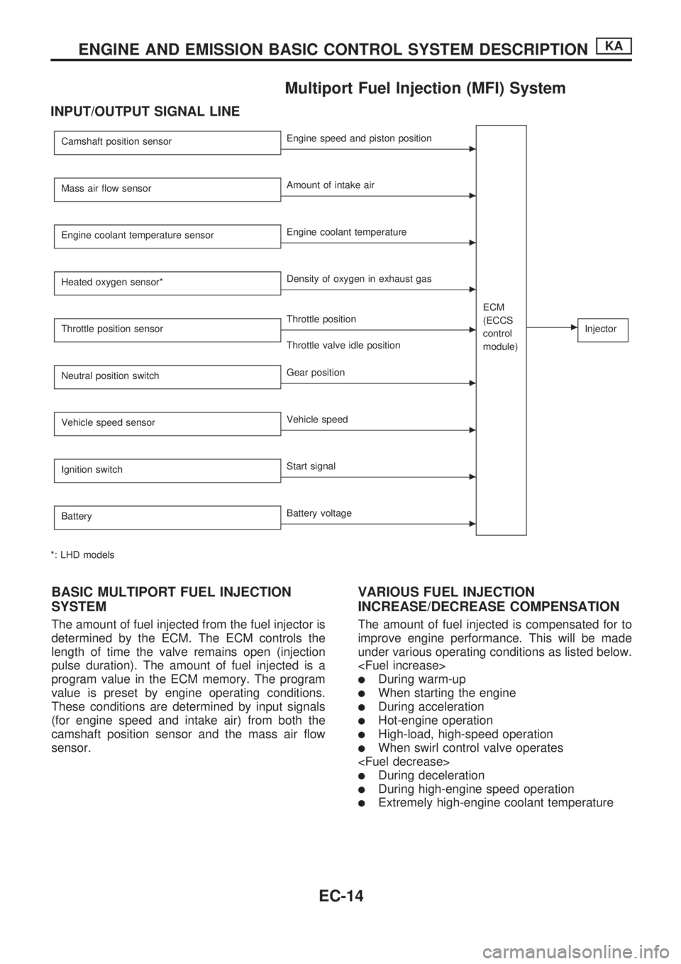
Multiport Fuel Injection (MFI) System
INPUT/OUTPUT SIGNAL LINE
Camshaft position sensorcEngine speed and piston position
ECM
(ECCS
control
module)
cInjector
Mass air flow sensorcAmount of intake air
Engine coolant temperature sensor
cEngine coolant temperature
Heated oxygen sensor*
cDensity of oxygen in exhaust gas
Throttle position sensor
cThrottle position
Throttle valve idle position
Neutral position switch
cGear position
Vehicle speed sensor
cVehicle speed
Ignition switch
cStart signal
Battery
cBattery voltage
*: LHD models
BASIC MULTIPORT FUEL INJECTION
SYSTEM
The amount of fuel injected from the fuel injector is
determined by the ECM. The ECM controls the
length of time the valve remains open (injection
pulse duration). The amount of fuel injected is a
program value in the ECM memory. The program
value is preset by engine operating conditions.
These conditions are determined by input signals
(for engine speed and intake air) from both the
camshaft position sensor and the mass air flow
sensor.
VARIOUS FUEL INJECTION
INCREASE/DECREASE COMPENSATION
The amount of fuel injected is compensated for to
improve engine performance. This will be made
under various operating conditions as listed below.
lDuring warm-up
lWhen starting the engine
lDuring acceleration
lHot-engine operation
lHigh-load, high-speed operation
lWhen swirl control valve operates
lDuring deceleration
lDuring high-engine speed operation
lExtremely high-engine coolant temperature
ENGINE AND EMISSION BASIC CONTROL SYSTEM DESCRIPTIONKA
EC-14
Page 298 of 1659
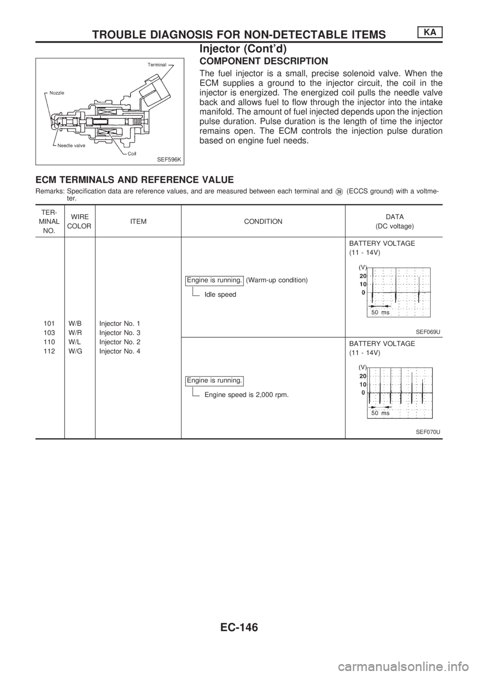
COMPONENT DESCRIPTION
The fuel injector is a small, precise solenoid valve. When the
ECM supplies a ground to the injector circuit, the coil in the
injector is energized. The energized coil pulls the needle valve
back and allows fuel to flow through the injector into the intake
manifold. The amount of fuel injected depends upon the injection
pulse duration. Pulse duration is the length of time the injector
remains open. The ECM controls the injection pulse duration
based on engine fuel needs.
ECM TERMINALS AND REFERENCE VALUE
Remarks: Specification data are reference values, and are measured between each terminal andV39(ECCS ground) with a voltme-
ter.
TER-
MINAL
NO.WIRE
COLORITEM CONDITIONDATA
(DC voltage)
101
103
110
112W/B
W/R
W/L
W/GInjector No. 1
Injector No. 3
Injector No. 2
Injector No. 4Engine is running.
(Warm-up condition)
Idle speedBATTERY VOLTAGE
(11 - 14V)
SEF069U
Engine is running.
Engine speed is 2,000 rpm.BATTERY VOLTAGE
(11 - 14V)
SEF070U
SEF596K
TROUBLE DIAGNOSIS FOR NON-DETECTABLE ITEMSKA
Injector (Cont'd)
EC-146
Page 420 of 1659
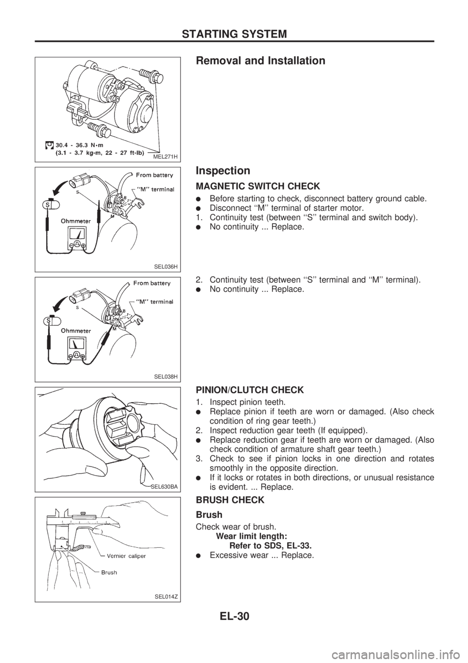
Removal and Installation
Inspection
MAGNETIC SWITCH CHECK
lBefore starting to check, disconnect battery ground cable.
lDisconnect ``M'' terminal of starter motor.
1. Continuity test (between ``S'' terminal and switch body).
lNo continuity ... Replace.
2. Continuity test (between ``S'' terminal and ``M'' terminal).
lNo continuity ... Replace.
PINION/CLUTCH CHECK
1. Inspect pinion teeth.
lReplace pinion if teeth are worn or damaged. (Also check
condition of ring gear teeth.)
2. Inspect reduction gear teeth (If equipped).
lReplace reduction gear if teeth are worn or damaged. (Also
check condition of armature shaft gear teeth.)
3. Check to see if pinion locks in one direction and rotates
smoothly in the opposite direction.
lIf it locks or rotates in both directions, or unusual resistance
is evident. ... Replace.
BRUSH CHECK
Brush
Check wear of brush.
Wear limit length:
Refer to SDS, EL-33.
lExcessive wear ... Replace.
MEL271H
SEL036H
SEL038H
SEL630BA
SEL014Z
STARTING SYSTEM
EL-30
Page 422 of 1659
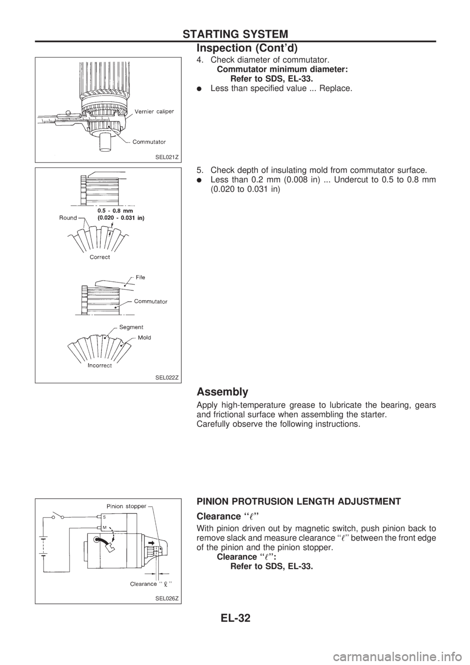
4. Check diameter of commutator.
Commutator minimum diameter:
Refer to SDS, EL-33.
lLess than specified value ... Replace.
5. Check depth of insulating mold from commutator surface.
lLess than 0.2 mm (0.008 in) ... Undercut to 0.5 to 0.8 mm
(0.020 to 0.031 in)
Assembly
Apply high-temperature grease to lubricate the bearing, gears
and frictional surface when assembling the starter.
Carefully observe the following instructions.
PINION PROTRUSION LENGTH ADJUSTMENT
Clearance ``!''
With pinion driven out by magnetic switch, push pinion back to
remove slack and measure clearance ``!'' between the front edge
of the pinion and the pinion stopper.
Clearance ``!'':
Refer to SDS, EL-33.
SEL021Z
SEL022Z
SEL026Z
STARTING SYSTEM
Inspection (Cont'd)
EL-32