service indicator NISSAN PICK-UP 1998 Repair Manual
[x] Cancel search | Manufacturer: NISSAN, Model Year: 1998, Model line: PICK-UP, Model: NISSAN PICK-UP 1998Pages: 1659, PDF Size: 53.39 MB
Page 27 of 1659
Disassembly
WARNING:
Do not place your fingers in front of piston.
CAUTION:
lDo not scratch or score cylinder wall.
lCL28VD type front disc brake uses plastic pistons,
handle them carefully.
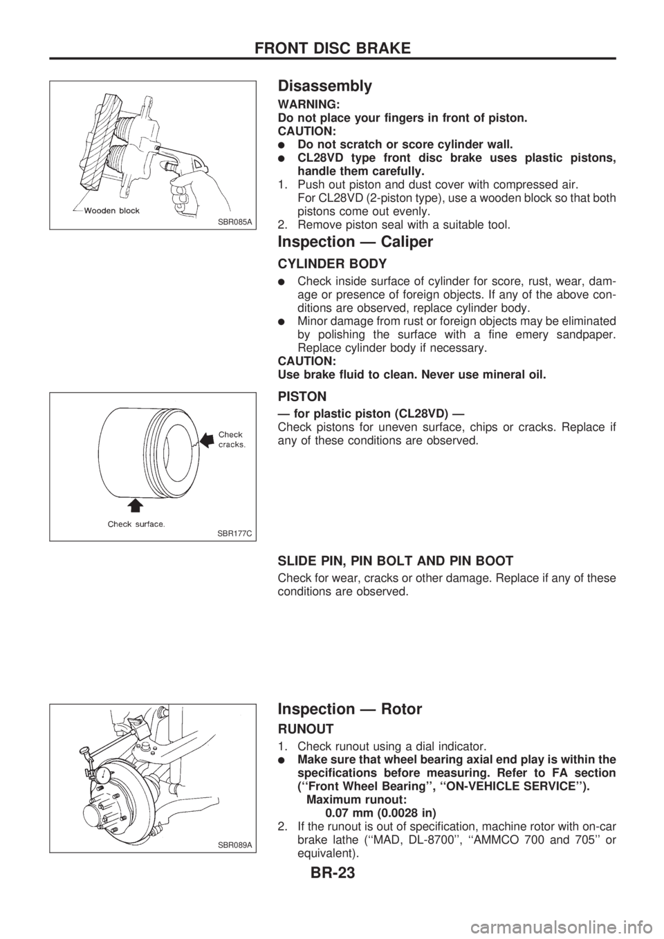
1. Push out piston and dust cover with compressed air.
For CL28VD (2-piston type), use a wooden block so that both
pistons come out evenly.
2. Remove piston seal with a suitable tool.
Inspection Ð Caliper
CYLINDER BODY
lCheck inside surface of cylinder for score, rust, wear, dam-
age or presence of foreign objects. If any of the above con-
ditions are observed, replace cylinder body.
lMinor damage from rust or foreign objects may be eliminated
by polishing the surface with a fine emery sandpaper.
Replace cylinder body if necessary.
CAUTION:
Use brake fluid to clean. Never use mineral oil.
PISTON
Ð for plastic piston (CL28VD) Ð
Check pistons for uneven surface, chips or cracks. Replace if
any of these conditions are observed.
SLIDE PIN, PIN BOLT AND PIN BOOT
Check for wear, cracks or other damage. Replace if any of these
conditions are observed.
Inspection Ð Rotor
RUNOUT
1. Check runout using a dial indicator.
lMake sure that wheel bearing axial end play is within the
specifications before measuring. Refer to FA section
(``Front Wheel Bearing'', ``ON-VEHICLE SERVICE'').
Maximum runout:
0.07 mm (0.0028 in)
2. If the runout is out of specification, machine rotor with on-car
brake lathe (``MAD, DL-8700'', ``AMMCO 700 and 705'' or
equivalent).
SBR085A
SBR177C
SBR089A
FRONT DISC BRAKE
BR-23
Page 150 of 1659
ENGINE CONTROL SYSTEM
SECTION
EC
CONTENTS
DIAGNOSTIC TROUBLE CODE INDEX................... 1
Alphabetical & Numerical Index for DTC
(KA engine) ............................................................ 1
PRECAUTIONS AND PREPARATION..................... 2
Special Service Tools ............................................ 2
Commercial Service Tool....................................... 4
Supplemental Restraint System (SRS) ``AIR
BAG'' (4WD models).............................................. 4
Supplemental Restraint System (SRS) ``AIR
BAG'' (2WD models).............................................. 4
KA
PRECAUTIONS AND PREPARATION..................... 5
Engine Fuel & Emission Control System .............. 5
Precautions ............................................................ 6
ENGINE AND EMISSION CONTROL OVERALL
SYSTEM..................................................................... 8
Circuit Diagram ...................................................... 8
System Diagram .................................................... 9
ECCS Component Parts Location ....................... 10
Vacuum Hose Drawing ........................................ 12
System Chart ....................................................... 13
ENGINE AND EMISSION BASIC CONTROL
SYSTEM DESCRIPTION..................................... 14
Multiport Fuel Injection (MFI) System.................. 14
Distributor Ignition (DI) System............................ 17
Air Conditioning Cut Control ................................ 18
Fuel Cut Control (at no load & high engine
speed) .................................................................. 18
EVAPORATIVE EMISSION SYSTEM..................... 19
Description ........................................................... 19
Inspection ............................................................. 19POSITIVE CRANKCASE VENTILATION................ 21
Description ........................................................... 21
Inspection ............................................................. 21
BASIC SERVICE PROCEDURE............................. 22
Fuel Pressure Release ........................................ 22
Fuel Pressure Check ........................................... 22
Injector Removal and Installation ........................ 23
Fast Idle Cam (FIC) Inspection and
Adjustment ........................................................... 24
Idle Speed/Ignition Timing/Idle Mixture Ratio
Adjustment ........................................................... 25
ON BOARD DIAGNOSTIC SYSTEM
DESCRIPTION......................................................... 36
Introduction .......................................................... 36
Diagnostic Trouble Code (DTC) .......................... 36
Malfunction Indicator Lamp (MIL) ........................ 38
CONSULT ............................................................ 45
TROUBLE DIAGNOSIS - Introduction.................. 54
Introduction .......................................................... 54
Diagnostic Worksheet .......................................... 54
TROUBLE DIAGNOSIS - Work Flow..................... 56
Work Flow ............................................................ 56
Description for Work Flow ................................... 57
TROUBLE DIAGNOSIS - Basic Inspection.......... 58
Basic Inspection ................................................... 58
TROUBLE DIAGNOSIS - General Description..... 61
Fail-Safe Chart ..................................................... 61
Symptom Matrix Chart ......................................... 62
CONSULT Reference Value in Data Monitor
Mode .................................................................... 64
Major Sensor Reference Graph in Data
Monitor Mode ....................................................... 66
ECM Terminals and Reference Value ................. 68
EC
Page 178 of 1659
START
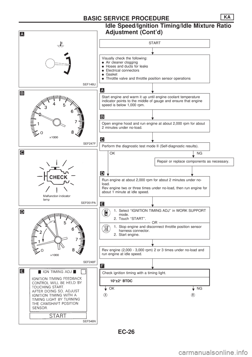
Visually check the following:lAir cleaner clogginglHoses and ducts for leakslElectrical connectorslGasketlThrottle valve and throttle position sensor operations
Start engine and warm it up until engine coolant temperature
indicator points to the middle of gauge and ensure that engine
speed is below 1,000 rpm.
Open engine hood and run engine at about 2,000 rpm for about
2 minutes under no-load.
Perform the diagnostic test mode II (Self-diagnostic results).
OKNG
Repair or replace components as necessary.
.
Run engine at about 2,000 rpm for about 2 minutes under no-
load.
Rev engine two or three times under no-load, then run engine for
about 1 minute at idle speed.
1. Select ``IGNITION TIMING ADJ'' in WORK SUPPORT
mode.
2. Touch ``START''.
----------------------------------------------------------------------------------------------------------------------------------------------------------------------------------------------------------------OR----------------------------------------------------------------------------------------------------------------------------------------------------------------------------------------------------------------
1. Stop engine and disconnect throttle position sensor
harness connector.
2. Start engine.
Rev engine (2,000 - 3,000 rpm) 2 or 3 times under no-load and
run engine at idle speed.
Check ignition timing with a timing light.
---------------------------------------------------------------------------------------------------------------------------------------------------------------------------------------------------------------------------------------------------------------------------------------------------------------------------------------------------------------------------------------------------------------------------------------------------------------------
10É 2É BTDC
OK NG
VAVB
SEF146U
SEF247F
SEF051PA
SEF248F
SEF546N
.
.
.
.
.
.
.
.
.
..
BASIC SERVICE PROCEDUREKA
Idle Speed/Ignition Timing/Idle Mixture Ratio
Adjustment (Cont'd)
EC-26
Page 180 of 1659
VC
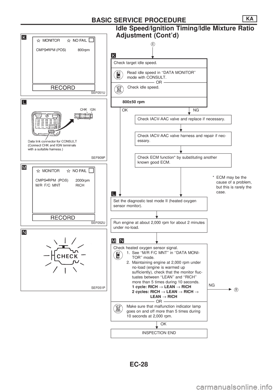
Check target idle speed.
-------------------------------------------------------------------------------------------------------------------------------------------------------------------------------------------------------------------------------------------------------------------------------------------------------------------------------------------------------------------------
Read idle speed in ``DATA MONITOR''
mode with CONSULT.
-----------------------------------------------------------------------------------------------------------------------------------------------------------------OR -----------------------------------------------------------------------------------------------------------------------------------------------------------------
Check idle speed.
-------------------------------------------------------------------------------------------------------------------------------------------------------------------------------------------------------------------------------------------------------------------------------------------------------------------------------------------------------------------------
800 50 rpm
OKNG
Check IACV-AAC valve and replace if necessary.
Check IACV-AAC valve harness and repair if nec-
essary.
Check ECM function* by substituting another
known good ECM.
* ECM may be the
cause of a problem,
but this is rarely the
case.
.
Set the diagnostic test mode II (heated oxygen
sensor monitor).
Run engine at about 2,000 rpm for about 2 minutes
under no-load.
Check heated oxygen sensor signal.
1. See ``M/R F/C MNT'' in ``DATA MONI-
TOR'' mode.
2. Maintaining engine at 2,000 rpm under
no-load (engine is warmed up
sufficiently), check that the monitor fluc-
tuates between ``LEAN'' and ``RICH''
more than 5 times during 10 seconds.
1 cycle: RICH®LEAN®RICH
2 cycles: RICH®LEAN®RICH®
LEAN®RICH
-----------------------------------------------------------------------------------------------------------------------------------------------------------------OR -----------------------------------------------------------------------------------------------------------------------------------------------------------------
Make sure that malfunction indicator lamp
goes on and off more than 5 times during
10 seconds at 2,000 rpm.
OK
cNG
VD
INSPECTION END
SEF051U
SEF909P
SEF052U
SEF051P
.
.
.
.
.
.
.
.
BASIC SERVICE PROCEDUREKA
Idle Speed/Ignition Timing/Idle Mixture Ratio
Adjustment (Cont'd)
EC-28
Page 181 of 1659
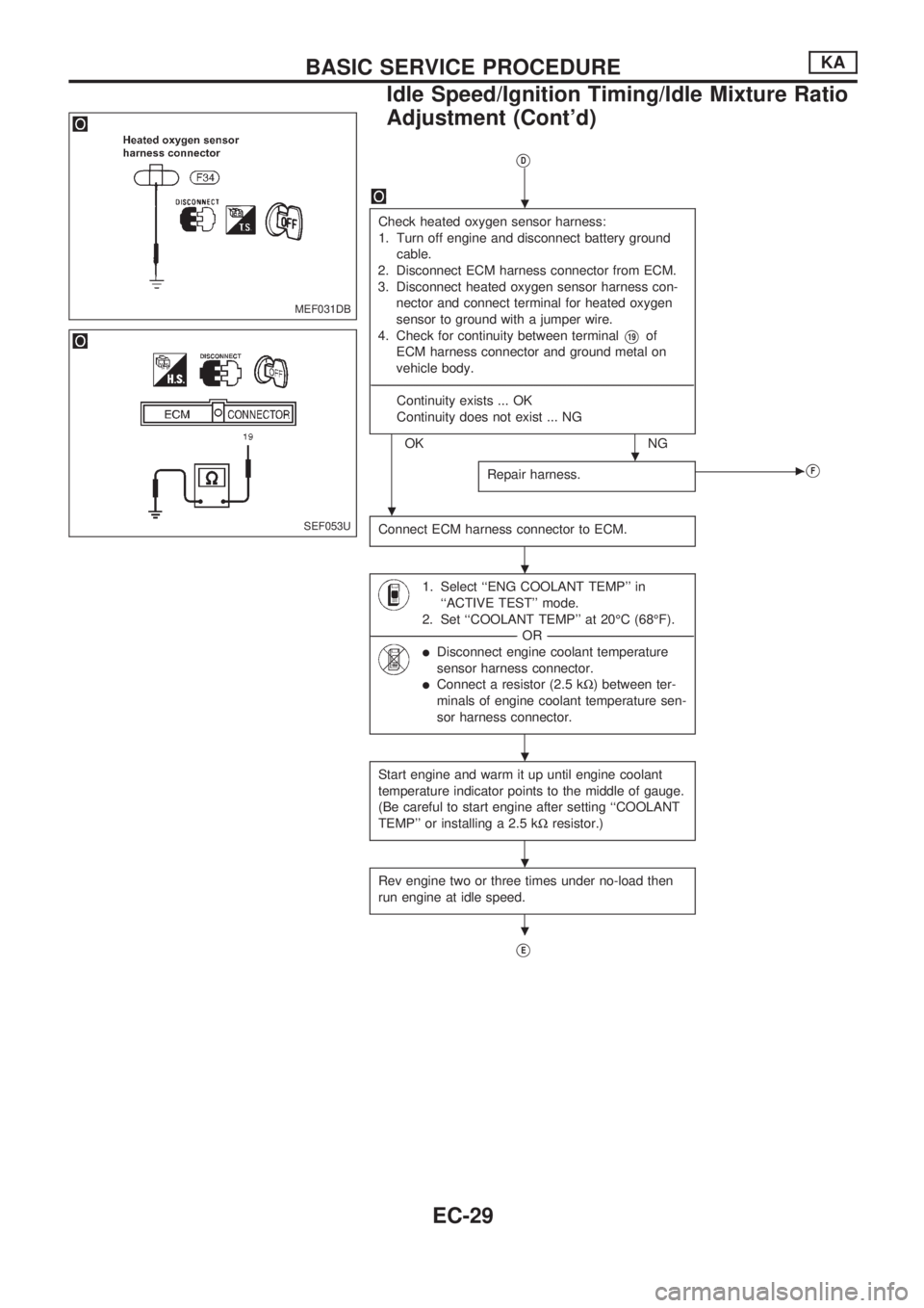
VD
Check heated oxygen sensor harness:
1. Turn off engine and disconnect battery ground
cable.
2. Disconnect ECM harness connector from ECM.
3. Disconnect heated oxygen sensor harness con-
nector and connect terminal for heated oxygen
sensor to ground with a jumper wire.
4. Check for continuity between terminal
V19of
ECM harness connector and ground metal on
vehicle body.
----------------------------------------------------------------------------------------------------------------------------------------------------------------------------------------------------------------------------------------------------------------------------------------------------------------------------------------------------------------------------
Continuity exists ... OK
Continuity does not exist ... NG
OK NG
Repair harness.
cVF
Connect ECM harness connector to ECM.
1. Select ``ENG COOLANT TEMP'' in
``ACTIVE TEST'' mode.
2. Set ``COOLANT TEMP'' at 20ÉC (68ÉF).
--------------------------------------------------------------------------------------------------------------------------------------------------------------------OR--------------------------------------------------------------------------------------------------------------------------------------------------------------------
lDisconnect engine coolant temperature
sensor harness connector.
lConnect a resistor (2.5 kW) between ter-
minals of engine coolant temperature sen-
sor harness connector.
Start engine and warm it up until engine coolant
temperature indicator points to the middle of gauge.
(Be careful to start engine after setting ``COOLANT
TEMP'' or installing a 2.5 kWresistor.)
Rev engine two or three times under no-load then
run engine at idle speed.
VE
MEF031DB
SEF053U
.
.
.
.
.
.
.
BASIC SERVICE PROCEDUREKA
Idle Speed/Ignition Timing/Idle Mixture Ratio
Adjustment (Cont'd)
EC-29
Page 182 of 1659
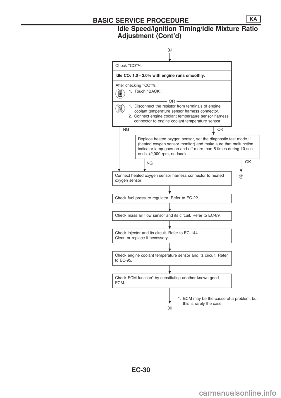
VE
Check ``CO''%.
-------------------------------------------------------------------------------------------------------------------------------------------------------------------------------------------------------------------------------------------------------------------------------------------------------------------------------------------------------------------------------------------------------------------------------------------------------
Idle CO: 1.0 - 2.0% with engine runs smoothly.
-------------------------------------------------------------------------------------------------------------------------------------------------------------------------------------------------------------------------------------------------------------------------------------------------------------------------------------------------------------------------------------------------------------------------------------------------------
After checking ``CO''%
1. Touch ``BACK''.
---------------------------------------------------------------------------------------------------------------------------------------------------------------------------------------------------------OR---------------------------------------------------------------------------------------------------------------------------------------------------------------------------------------------------------
1. Disconnect the resistor from terminals of engine
coolant temperature sensor harness connector.
2. Connect engine coolant temperature sensor harness
connector to engine coolant temperature sensor.
NG OK
Replace heated oxygen sensor, set the diagnostic test mode II
(heated oxygen sensor monitor) and make sure that malfunction
indicator lamp goes on and off more than 5 times during 10 sec-
onds. (2,000 rpm, no-load)
NGOK
.
Connect heated oxygen sensor harness connector to heated
oxygen sensor.VF
Check fuel pressure regulator. Refer to EC-22.
Check mass air flow sensor and its circuit. Refer to EC-89.
Check injector and its circuit. Refer to EC-144.
Clean or replace if necessary.
Check engine coolant temperature sensor and its circuit. Refer
to EC-95.
Check ECM function* by substituting another known good
ECM.
*: ECM may be the cause of a problem, but
this is rarely the case.
VB
.
.
..
.
.
.
.
.
.
BASIC SERVICE PROCEDUREKA
Idle Speed/Ignition Timing/Idle Mixture Ratio
Adjustment (Cont'd)
EC-30
Page 207 of 1659
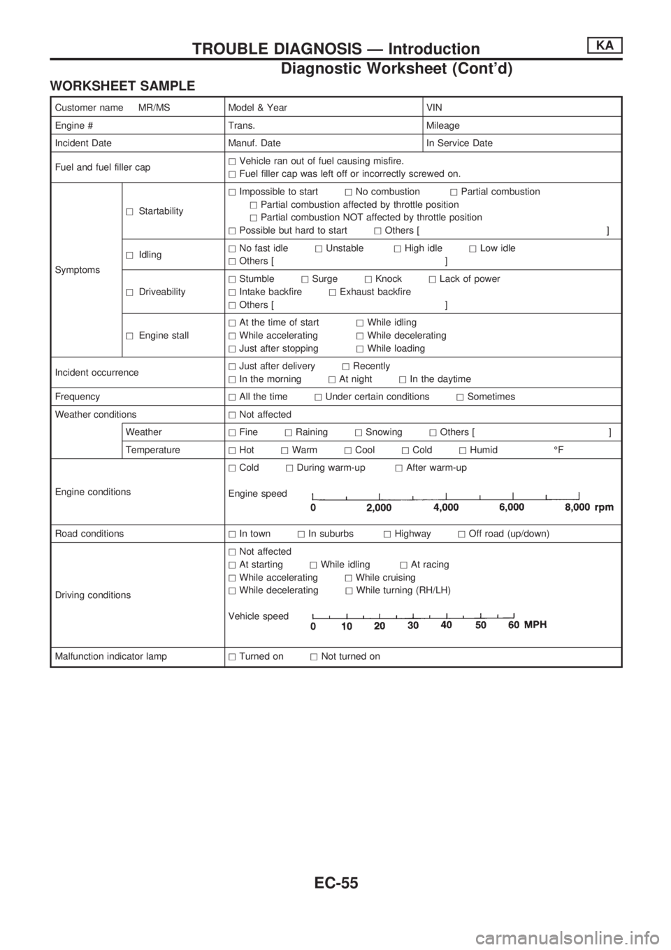
WORKSHEET SAMPLE
Customer name MR/MS Model & Year VIN
Engine # Trans. Mileage
Incident Date Manuf. Date In Service Date
Fuel and fuel filler caphVehicle ran out of fuel causing misfire.
hFuel filler cap was left off or incorrectly screwed on.
SymptomshStartabilityhImpossible to starthNo combustionhPartial combustion
hPartial combustion affected by throttle position
hPartial combustion NOT affected by throttle position
hPossible but hard to starthOthers [ ]
hIdlinghNo fast idlehUnstablehHigh idlehLow idle
hOthers [ ]
hDriveabilityhStumblehSurgehKnockhLack of power
hIntake backfirehExhaust backfire
hOthers [ ]
hEngine stallhAt the time of starthWhile idling
hWhile acceleratinghWhile decelerating
hJust after stoppinghWhile loading
Incident occurrencehJust after deliveryhRecently
hIn the morninghAt nighthIn the daytime
FrequencyhAll the timehUnder certain conditionshSometimes
Weather conditionshNot affected
WeatherhFinehRaininghSnowinghOthers [ ]
TemperaturehHothWarmhCoolhColdhHumid ÉF
Engine conditionshColdhDuring warm-uphAfter warm-up
Engine speed
Road conditionshIn townhIn suburbshHighwayhOff road (up/down)
Driving conditionshNot affected
hAt startinghWhile idlinghAt racing
hWhile acceleratinghWhile cruising
hWhile deceleratinghWhile turning (RH/LH)
Vehicle speed
Malfunction indicator lamphTurned onhNot turned on
TROUBLE DIAGNOSIS Ð IntroductionKA
Diagnostic Worksheet (Cont'd)
EC-55
Page 578 of 1659
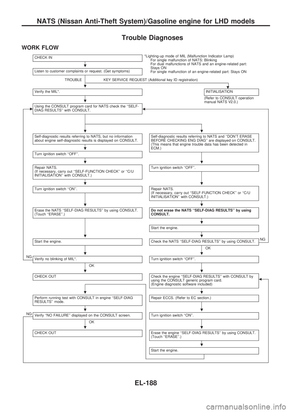
Trouble Diagnoses
WORK FLOW
CHECK IN*Lighting-up mode of MIL (Malfunction Indicator Lamp)
For single malfunction of NATS: Blinking
For dual malfunctions of NATS and an engine-related part:
Stays ON
For single malfunction of an engine-related part: Stays ON Listen to customer complaints or request. (Get symptoms)
TROUBLE KEY SERVICE REQUEST (Additional key ID registration)
.Verify the MIL*.INITIALISATION
(Refer to CONSULT operation
manual NATS V2.0.)
cUsing the CONSULT program card for NATS check the ``SELF-
DIAG RESULTS'' with CONSULT.b
Self-diagnostic results referring to NATS, but no information
about engine self-diagnostic results is displayed on CONSULT.Self-diagnostic results referring to NATS and ``DON'T ERASE
BEFORE CHECKING ENG DIAG'' are displayed on CONSULT.
(This means that engine trouble data has been detected in
ECM.)
Turn ignition switch ``OFF''.
Repair NATS.
(If necessary, carry out ``SELF-FUNCTION CHECK'' or ``C/U
INITIALISATION'' with CONSULT.)Turn ignition switch ``OFF''.
Turn ignition switch ``ON''.Repair NATS.
(If necessary, carry out ``SELF-FUNCTION CHECK'' or ``C/U
INITIALISATION'' with CONSULT.)
Erase the NATS ``SELF-DIAG RESULTS'' by using CONSULT.
(Touch ``ERASE''.)Do not erase the NATS ``SELF-DIAG RESULTS'' by using
CONSULT.
Start the engine.
Start the engine.Check the NATS ``SELF-DIAG RESULTS'' by using CONSULT.
OKNG
NGVerify no blinking of MIL*.
OKTurn ignition switch ``OFF''.
CHECK OUTCheck the engine ``SELF-DIAG RESULTS'' with CONSULT by
using the CONSULT generic program card.
(Engine diagnostic software included)b
Perform running test with CONSULT in engine ``SELF-DIAG
RESULTS'' mode.Repair ECCS. (Refer to EC section.)
NGVerify ``NO FAILURE'' displayed on the CONSULT screen.
OKTurn ignition switch ``ON''.
CHECK OUTErase the engine ``SELF-DIAG RESULTS'' by using CONSULT.
(Touch ``ERASE''.)
Start the engine.
.
.
.
..
.
..
..
..
.
..
..
..
..
..
..
.
NATS (Nissan Anti-Theft System)/Gasoline engine for LHD models
EL-188
Page 741 of 1659
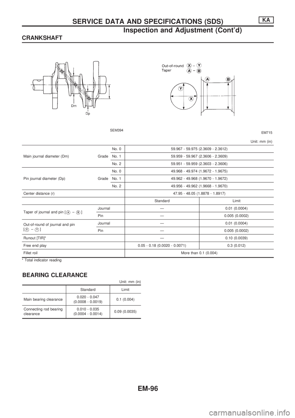
CRANKSHAFT
SEM394EM715
Unit: mm (in)
Main journal diameter (Dm) GradeNo. 0 59.967 - 59.975 (2.3609 - 2.3612)
No. 1 59.959 - 59.967 (2.3606 - 2.3609)
No. 2 59.951 - 59.959 (2.3603 - 2.3606)
Pin journal diameter (Dp) GradeNo. 0 49.968 - 49.974 (1.9672 - 1.9675)
No. 1 49.962 - 49.968 (1.9670 - 1.9672)
No. 2 49.956 - 49.962 (1.9668 - 1.9670)
Center distance (r) 47.95 - 48.05 (1.8878 - 1.8917)
Standard Limit
Taper of journal and pin [
VA±VB]Journal Ð 0.01 (0.0004)
Pin Ð 0.005 (0.0002)
Out-of-round of journal and pin
[
VX±VY]Journal Ð 0.01 (0.0004)
Pin Ð 0.005 (0.0002)
Runout [TIR]* Ð 0.10 (0.0039)
Free end play 0.05 - 0.18 (0.0020 - 0.0071) 0.3 (0.012)
Fillet roilMore than 0.1 (0.004)
* Total indicator reading
BEARING CLEARANCE
Unit: mm (in)
Standard Limit
Main bearing clearance0.020 - 0.047
(0.0008 - 0.0019)0.1 (0.004)
Connecting rod bearing
clearance0.010 - 0.035
(0.0004 - 0.0014)0.09 (0.0035)
SERVICE DATA AND SPECIFICATIONS (SDS)KA
Inspection and Adjustment (Cont'd)
EM-96
Page 742 of 1659
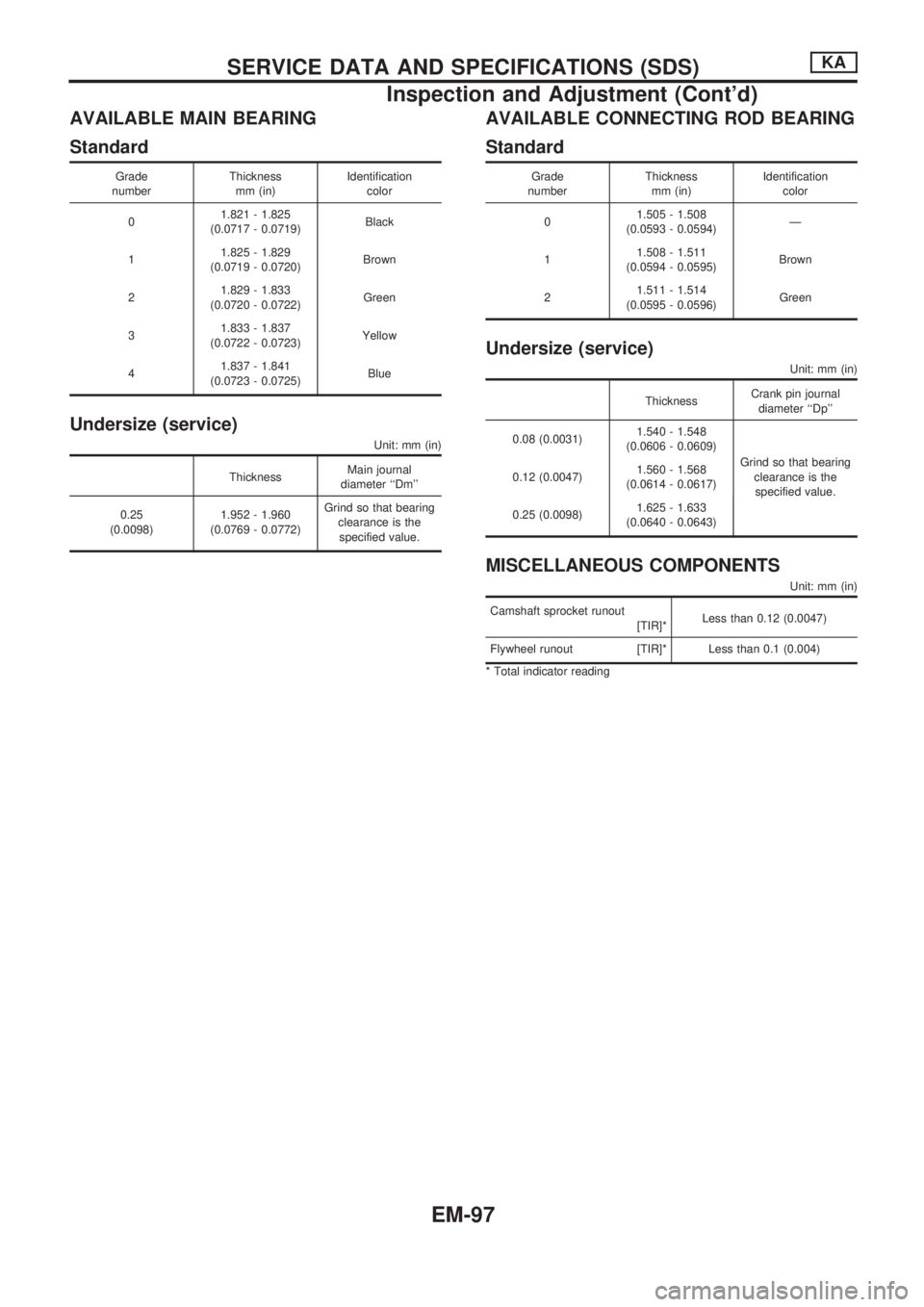
AVAILABLE MAIN BEARING
Standard
Grade
numberThickness
mm (in)Identification
color
01.821 - 1.825
(0.0717 - 0.0719)Black
11.825 - 1.829
(0.0719 - 0.0720)Brown
21.829 - 1.833
(0.0720 - 0.0722)Green
31.833 - 1.837
(0.0722 - 0.0723)Yellow
41.837 - 1.841
(0.0723 - 0.0725)Blue
Undersize (service)
Unit: mm (in)
ThicknessMain journal
diameter ``Dm''
0.25
(0.0098)1.952 - 1.960
(0.0769 - 0.0772)Grind so that bearing
clearance is the
specified value.
AVAILABLE CONNECTING ROD BEARING
Standard
Grade
numberThickness
mm (in)Identification
color
01.505 - 1.508
(0.0593 - 0.0594)Ð
11.508 - 1.511
(0.0594 - 0.0595)Brown
21.511 - 1.514
(0.0595 - 0.0596)Green
Undersize (service)
Unit: mm (in)
ThicknessCrank pin journal
diameter ``Dp''
0.08 (0.0031)1.540 - 1.548
(0.0606 - 0.0609)
Grind so that bearing
clearance is the
specified value. 0.12 (0.0047)1.560 - 1.568
(0.0614 - 0.0617)
0.25 (0.0098)1.625 - 1.633
(0.0640 - 0.0643)
MISCELLANEOUS COMPONENTS
Unit: mm (in)
Camshaft sprocket runout
[TIR]*Less than 0.12 (0.0047)
Flywheel runout [TIR]* Less than 0.1 (0.004)
* Total indicator reading
SERVICE DATA AND SPECIFICATIONS (SDS)KA
Inspection and Adjustment (Cont'd)
EM-97