turn signal NISSAN PICK-UP 1998 Repair Manual
[x] Cancel search | Manufacturer: NISSAN, Model Year: 1998, Model line: PICK-UP, Model: NISSAN PICK-UP 1998Pages: 1659, PDF Size: 53.39 MB
Page 38 of 1659
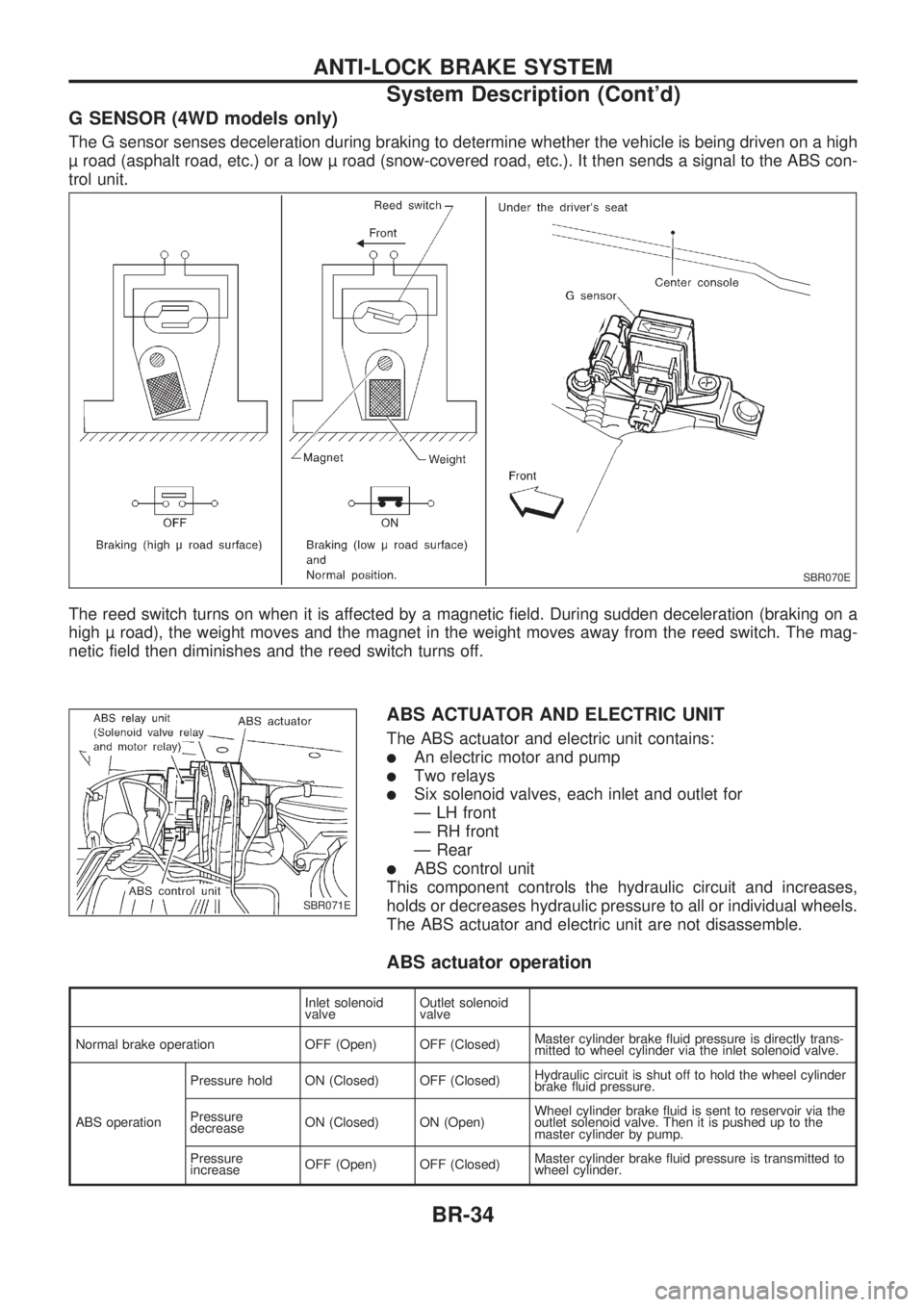
G SENSOR (4WD models only)
The G sensor senses deceleration during braking to determine whether the vehicle is being driven on a high
road (asphalt road, etc.) or a low road (snow-covered road, etc.). It then sends a signal to the ABS con-
trol unit.
The reed switch turns on when it is affected by a magnetic field. During sudden deceleration (braking on a
high road), the weight moves and the magnet in the weight moves away from the reed switch. The mag-
netic field then diminishes and the reed switch turns off.
ABS ACTUATOR AND ELECTRIC UNIT
The ABS actuator and electric unit contains:
lAn electric motor and pump
lTwo relays
lSix solenoid valves, each inlet and outlet for
Ð LH front
Ð RH front
Ð Rear
lABS control unit
This component controls the hydraulic circuit and increases,
holds or decreases hydraulic pressure to all or individual wheels.
The ABS actuator and electric unit are not disassemble.
ABS actuator operation
Inlet solenoid
valveOutlet solenoid
valve
Normal brake operation OFF (Open) OFF (Closed)Master cylinder brake fluid pressure is directly trans-
mitted to wheel cylinder via the inlet solenoid valve.
ABS operationPressure hold ON (Closed) OFF (Closed)Hydraulic circuit is shut off to hold the wheel cylinder
brake fluid pressure.
Pressure
decreaseON (Closed) ON (Open)Wheel cylinder brake fluid is sent to reservoir via the
outlet solenoid valve. Then it is pushed up to the
master cylinder by pump.
Pressure
increaseOFF (Open) OFF (Closed)Master cylinder brake fluid pressure is transmitted to
wheel cylinder.
SBR070E
SBR071E
ANTI-LOCK BRAKE SYSTEM
System Description (Cont'd)
BR-34
Page 62 of 1659
![NISSAN PICK-UP 1998 Repair Manual SELF-DIAGNOSTIC RESULTS MODE
Diagnostic item Diagnostic item is detected when ...Diagnostic
procedure
FR RH SENSOR.1
[OPEN]
lCircuit for front right wheel sensor is open.
(An abnormally high input vol NISSAN PICK-UP 1998 Repair Manual SELF-DIAGNOSTIC RESULTS MODE
Diagnostic item Diagnostic item is detected when ...Diagnostic
procedure
FR RH SENSOR.1
[OPEN]
lCircuit for front right wheel sensor is open.
(An abnormally high input vol](/img/5/57374/w960_57374-61.png)
SELF-DIAGNOSTIC RESULTS MODE
Diagnostic item Diagnostic item is detected when ...Diagnostic
procedure
FR RH SENSOR.1
[OPEN]
lCircuit for front right wheel sensor is open.
(An abnormally high input voltage is entered.)1
FR LH SENSOR.1
[OPEN]
lCircuit for front left wheel sensor is open.
(An abnormally high input voltage is entered.)1
RR SENSOR.1,.2
[OPEN]
lCircuit for rear sensor is open.
(An abnormal high input voltage is entered.)1
RR RH SENSOR.1,.3
[OPEN]
lCircuit for rear right sensor is open.
(An abnormally high input voltage is entered.)1
RR LH SENSOR.1,.3
[OPEN]
lCircuit for rear left sensor is open.
(An abnormally high input voltage is entered.)1
FR RH SENSOR.1
[SHORT]
lCircuit for front right wheel sensor is shorted.
(An abnormally low input voltage is entered.)1
FR LH SENSOR.1
[SHORT]
lCircuit for front left wheel sensor is shorted.
(An abnormally low input voltage is entered.)1
RR SENSOR.1,.2
[SHORT]
lCircuit for rear sensor is shorted.
(An abnormal low input voltage is entered.)1
RR RH SENSOR.1,.3
[SHORT]
lCircuit for rear right sensor is shorted.
(An abnormally low input voltage is entered.)1
RR LH SENSOR.1,.3
[SHORT]
lCircuit for rear left sensor is shorted.
(An abnormally low input voltage is entered.)1
ABS SENSOR.1
[ABNORMAL SIGNAL]
lTeeth damage on sensor rotor or improper installation of wheel sensor.
(Abnormal wheel sensor signal is entered.)1
FR RH IN ABS SOL
[OPEN]
lCircuit for front right inlet solenoid valve is open.
(An abnormally low output voltage is entered.)2
FR LH IN ABS SOL
[OPEN]
lCircuit for front left inlet solenoid valve is open.
(An abnormally low output voltage is entered.)2
RR IN ABS SOL
[OPEN]
lCircuit for rear inlet solenoid valve is open.
(An abnormally low output voltage is entered.)2
FR RH IN ABS SOL
[SHORT]
lCircuit for front right inlet solenoid valve is shorted.
(An abnormally high output voltage is entered.)2
FR LH IN ABS SOL
[SHORT]
lCircuit for front left inlet solenoid valve is shorted.
(An abnormally high output voltage is entered.)2
RR IN ABS SOL
[SHORT]
lCircuit for rear inlet solenoid valve is shorted.
(An abnormally high output voltage is entered.)2
FR RH OUT ABS SOL
[OPEN]
lCircuit for front right outlet solenoid valve is open.
(An abnormally low output voltage is entered.)2
FR LH OUT ABS SOL
[OPEN]
lCircuit for front left outlet solenoid valve is open.
(An abnormally low output voltage is entered.)2
RR OUT ABS SOL
[OPEN]
lCircuit for rear outlet solenoid valve is open.
(An abnormally low output voltage is entered.)2
FR RH OUT ABS SOL
[SHORT]
lCircuit for front right outlet solenoid valve is shorted.
(An abnormally high output voltage is entered.)2
FR LH OUT ABS SOL
[SHORT]
lCircuit for front left outlet solenoid valve is shorted.
(An abnormally high output voltage is entered.)2
RR OUT ABS SOL
[SHORT]
lCircuit for rear outlet solenoid valve is shorted.
(An abnormally high output voltage is entered.)2
ABS ACTUATOR RELAY
[ABNORMAL]
lActuator solenoid valve relay is ON, even if control unit sends off signal.lActuator solenoid valve relay is OFF, even if control unit sends on signal.2
ABS MOTOR RELAY
[ABNORMAL]
lCircuit for ABS motor relay is open or shorted.lCircuit for actuator motor is open or shorted.lActuator motor relay is stuck.3
BATTERY VOLT
[VB-LOW]
lPower source voltage supplied to ABS control unit is abnormally low. 4
CONTROL UNIT
lFunction of calculation in ABS control unit has failed. 6
G-SENSOR.3
[ABNORMAL]
lG sensor circuit is open or shorted. 5
.1: If one or more wheels spin on a rough or slippery road for 40 seconds or more, the ABS warning lamp will illuminate. This
does not indicate a malfunction. Only in the case of the short-circuit (Code Nos. 26, 22, 32 and 36), after repair the ABS warn-
ing lamp also illuminates when the ignition switch is turned ``ON''. In this case, drive the vehicle at speeds greater than 30 km/h
(19 MPH) for approximately 1 minute as specified in ``SELF-DIAGNOSIS PROCEDURE'', BR-53. Check to ensure that the ABS
warning lamp goes out while the vehicle is being driven.
.2: 2WD model only
.3: 4WD model only
TROUBLE DIAGNOSES
CONSULT Inspection Procedure (Cont'd)
BR-58
Page 65 of 1659
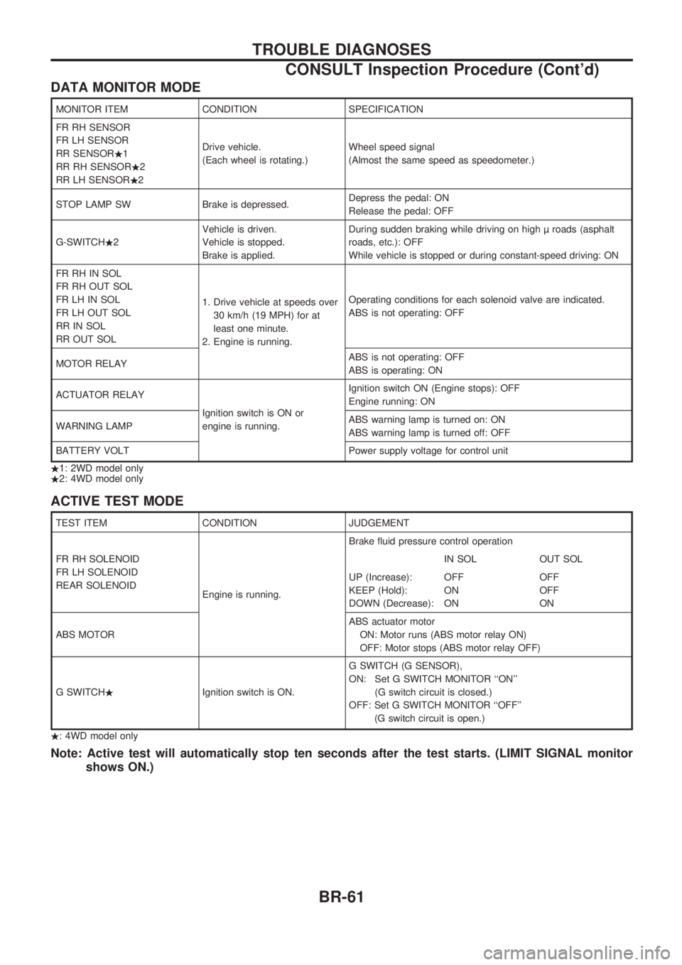
DATA MONITOR MODE
MONITOR ITEM CONDITION SPECIFICATION
FR RH SENSOR
FR LH SENSOR
RR SENSOR.1
RR RH SENSOR.2
RR LH SENSOR.2Drive vehicle.
(Each wheel is rotating.)Wheel speed signal
(Almost the same speed as speedometer.)
STOP LAMP SW Brake is depressed.Depress the pedal: ON
Release the pedal: OFF
G-SWITCH.2Vehicle is driven.
Vehicle is stopped.
Brake is applied.During sudden braking while driving on high roads (asphalt
roads, etc.): OFF
While vehicle is stopped or during constant-speed driving: ON
FR RH IN SOL
FR RH OUT SOL
FR LH IN SOL
FR LH OUT SOL
RR IN SOL
RR OUT SOL1. Drive vehicle at speeds over
30 km/h (19 MPH) for at
least one minute.
2. Engine is running.Operating conditions for each solenoid valve are indicated.
ABS is not operating: OFF
MOTOR RELAYABS is not operating: OFF
ABS is operating: ON
ACTUATOR RELAY
Ignition switch is ON or
engine is running.Ignition switch ON (Engine stops): OFF
Engine running: ON
WARNING LAMPABS warning lamp is turned on: ON
ABS warning lamp is turned off: OFF
BATTERY VOLT Power supply voltage for control unit
.1: 2WD model only
.2: 4WD model only
ACTIVE TEST MODE
TEST ITEM CONDITION JUDGEMENT
FR RH SOLENOID
FR LH SOLENOID
REAR SOLENOID
Engine is running.Brake fluid pressure control operation
IN SOL OUT SOL
UP (Increase):
KEEP (Hold):
DOWN (Decrease):OFF
ON
ONOFF
OFF
ON
ABS MOTORABS actuator motor
ON: Motor runs (ABS motor relay ON)
OFF: Motor stops (ABS motor relay OFF)
G SWITCH.Ignition switch is ON.G SWITCH (G SENSOR),
ON: Set G SWITCH MONITOR ``ON''
(G switch circuit is closed.)
OFF: Set G SWITCH MONITOR ``OFF''
(G switch circuit is open.)
.: 4WD model only
Note: Active test will automatically stop ten seconds after the test starts. (LIMIT SIGNAL monitor
shows ON.)
TROUBLE DIAGNOSES
CONSULT Inspection Procedure (Cont'd)
BR-61
Page 158 of 1659
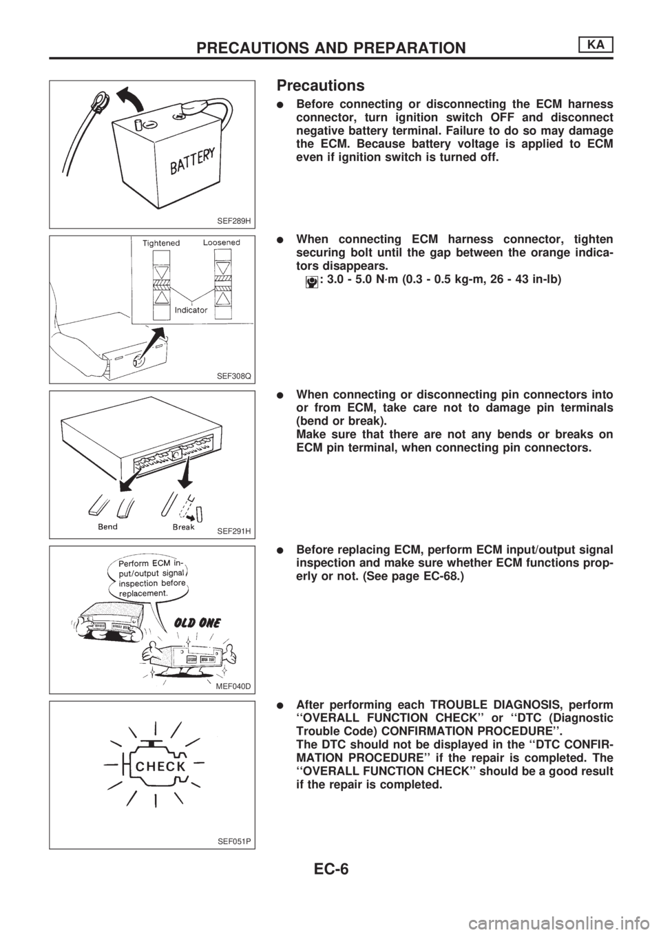
Precautions
lBefore connecting or disconnecting the ECM harness
connector, turn ignition switch OFF and disconnect
negative battery terminal. Failure to do so may damage
the ECM. Because battery voltage is applied to ECM
even if ignition switch is turned off.
lWhen connecting ECM harness connector, tighten
securing bolt until the gap between the orange indica-
tors disappears.
: 3.0 - 5.0 N´m (0.3 - 0.5 kg-m, 26 - 43 in-lb)
lWhen connecting or disconnecting pin connectors into
or from ECM, take care not to damage pin terminals
(bend or break).
Make sure that there are not any bends or breaks on
ECM pin terminal, when connecting pin connectors.
lBefore replacing ECM, perform ECM input/output signal
inspection and make sure whether ECM functions prop-
erly or not. (See page EC-68.)
lAfter performing each TROUBLE DIAGNOSIS, perform
``OVERALL FUNCTION CHECK'' or ``DTC (Diagnostic
Trouble Code) CONFIRMATION PROCEDURE''.
The DTC should not be displayed in the ``DTC CONFIR-
MATION PROCEDURE'' if the repair is completed. The
``OVERALL FUNCTION CHECK'' should be a good result
if the repair is completed.
SEF289H
SEF308Q
SEF291H
MEF040D
SEF051P
PRECAUTIONS AND PREPARATIONKA
EC-6
Page 170 of 1659
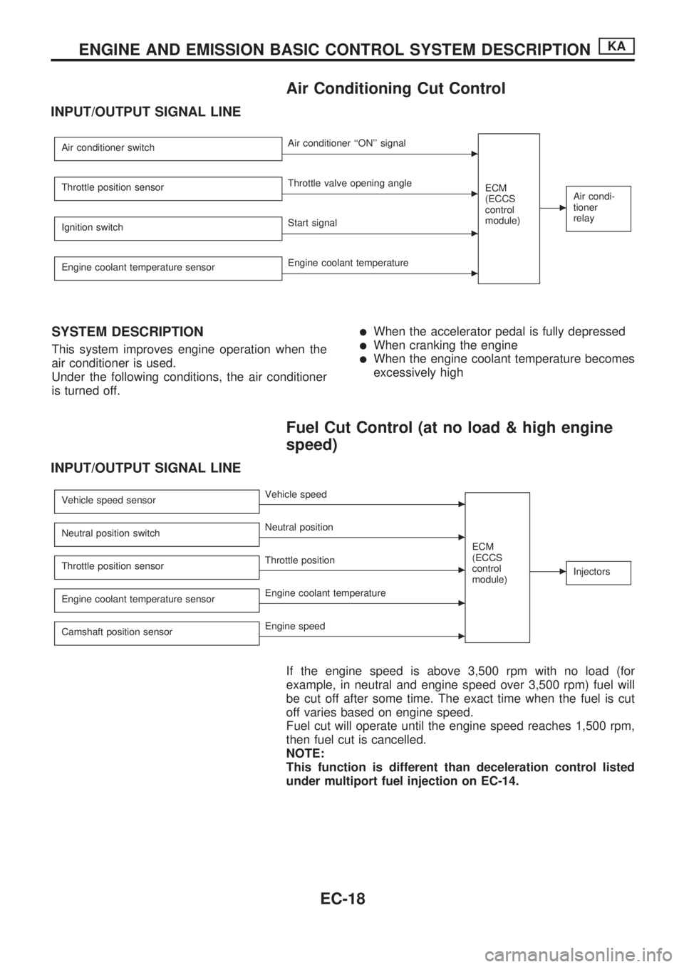
Air Conditioning Cut Control
INPUT/OUTPUT SIGNAL LINE
Air conditioner switchcAir conditioner ``ON'' signal
ECM
(ECCS
control
module)
cAir condi-
tioner
relayThrottle position sensorcThrottle valve opening angle
Ignition switch
cStart signal
Engine coolant temperature sensor
cEngine coolant temperature
SYSTEM DESCRIPTION
This system improves engine operation when the
air conditioner is used.
Under the following conditions, the air conditioner
is turned off.
lWhen the accelerator pedal is fully depressed
lWhen cranking the engine
lWhen the engine coolant temperature becomes
excessively high
Fuel Cut Control (at no load & high engine
speed)
INPUT/OUTPUT SIGNAL LINE
Vehicle speed sensorcVehicle speed
ECM
(ECCS
control
module)
cInjectors
Neutral position switchcNeutral position
Throttle position sensor
cThrottle position
Engine coolant temperature sensor
cEngine coolant temperature
Camshaft position sensor
cEngine speed
If the engine speed is above 3,500 rpm with no load (for
example, in neutral and engine speed over 3,500 rpm) fuel will
be cut off after some time. The exact time when the fuel is cut
off varies based on engine speed.
Fuel cut will operate until the engine speed reaches 1,500 rpm,
then fuel cut is cancelled.
NOTE:
This function is different than deceleration control listed
under multiport fuel injection on EC-14.
ENGINE AND EMISSION BASIC CONTROL SYSTEM DESCRIPTIONKA
EC-18
Page 198 of 1659
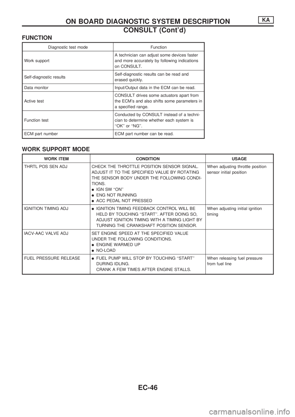
FUNCTION
Diagnostic test mode Function
Work supportA technician can adjust some devices faster
and more accurately by following indications
on CONSULT.
Self-diagnostic resultsSelf-diagnostic results can be read and
erased quickly.
Data monitor Input/Output data in the ECM can be read.
Active testCONSULT drives some actuators apart from
the ECM's and also shifts some parameters in
a specified range.
Function testConducted by CONSULT instead of a techni-
cian to determine whether each system is
``OK'' or ``NG''.
ECM part number ECM part number can be read.
WORK SUPPORT MODE
WORK ITEM CONDITION USAGE
THRTL POS SEN ADJ CHECK THE THROTTLE POSITION SENSOR SIGNAL.
ADJUST IT TO THE SPECIFIED VALUE BY ROTATING
THE SENSOR BODY UNDER THE FOLLOWING CONDI-
TIONS.
lIGN SW ``ON''
lENG NOT RUNNING
lACC PEDAL NOT PRESSEDWhen adjusting throttle position
sensor initial position
IGNITION TIMING ADJ
lIGNITION TIMING FEEDBACK CONTROL WILL BE
HELD BY TOUCHING ``START''. AFTER DOING SO,
ADJUST IGNITION TIMING WITH A TIMING LIGHT BY
TURNING THE CRANKSHAFT POSITION SENSOR.When adjusting initial ignition
timing
IACV-AAC VALVE ADJ SET ENGINE SPEED AT THE SPECIFIED VALUE
UNDER THE FOLLOWING CONDITIONS.
lENGINE WARMED UP
lNO-LOAD
FUEL PRESSURE RELEASE
lFUEL PUMP WILL STOP BY TOUCHING ``START''
DURING IDLING.
CRANK A FEW TIMES AFTER ENGINE STALLS.When releasing fuel pressure
from fuel line
ON BOARD DIAGNOSTIC SYSTEM DESCRIPTIONKA
CONSULT (Cont'd)
EC-46
Page 200 of 1659
![NISSAN PICK-UP 1998 Repair Manual SELF-DIAGNOSTIC MODE
Regarding items detected in ``SELF-DIAG RESULTS mode, refer to ``DIAGNOSTIC TROUBLE CODE
INDEX, EC-1.
DATA MONITOR MODE
Monitored item
[Unit]ECM
input
signalsMain
signalsDescr NISSAN PICK-UP 1998 Repair Manual SELF-DIAGNOSTIC MODE
Regarding items detected in ``SELF-DIAG RESULTS mode, refer to ``DIAGNOSTIC TROUBLE CODE
INDEX, EC-1.
DATA MONITOR MODE
Monitored item
[Unit]ECM
input
signalsMain
signalsDescr](/img/5/57374/w960_57374-199.png)
SELF-DIAGNOSTIC MODE
Regarding items detected in ``SELF-DIAG RESULTS'' mode, refer to ``DIAGNOSTIC TROUBLE CODE
INDEX'', EC-1.
DATA MONITOR MODE
Monitored item
[Unit]ECM
input
signalsMain
signalsDescription Remarks
CMPSRPM
(POS) [rpm]
jj
lIndicates the engine speed computed
from the POS signal (1É signal) of the
camshaft position sensor.
MAS AIR/FL SE [V]
jjlThe signal voltage of the mass air flow
sensor is displayed.lWhen the engine is stopped, a certain
value is indicated.
COOLAN TEMP/S
[ÉC] or [ÉF]
jj
lThe engine coolant temperature (deter-
mined by the signal voltage of the engine
coolant temperature sensor) is displayed.lWhen the engine coolant temperature
sensor is open or short-circuited, ECM
enters fail-safe mode. The engine coolant
temperature determined by the ECM is
displayed.
O2 SEN [V]
jjlThe signal voltage of the heated oxygen
sensor is displayed.lLHD models only
M/R F/C MNT
[RICH/LEAN]
jj
lDisplay of heated oxygen sensor signal
during air-fuel ratio feedback control:
RICH ... means the mixture became
``rich'', and control is being affected
toward a leaner mixture.
LEAN ... means the mixture became
``lean'', and control is being affected
toward a rich mixture.lAfter turning ON the ignition switch,
``RICH'' is displayed until air-fuel mixture
ratio feedback control begins.
lWhen the air-fuel ratio feedback is
clamped, the value just before the clamp-
ing is displayed continuously.
lLHD models only
VHCL SPEED SE
[km/h] or [mph]
jjlThe vehicle speed computed from the
vehicle speed sensor signal is displayed.
BATTERY VOLT [V]
jjlThe power supply voltage of ECM is dis-
played.
THRTL POS SEN [V]
jjlThe throttle position sensor signal volt-
age is displayed.
INT/A TEMP SE
[ÉC] or [ÉF]
j
lThe intake air temperature (determined
by the signal voltage of the intake air
temperature sensor) is indicated.
START SIGNAL
[ON/OFF]
jjlIndicates [ON/OFF] condition from the
starter signal.lAfter starting the engine, [OFF] is
displayed regardless of the starter signal.
CLSD THL/POSI
[ON/OFF]
jj
lIndicates [ON/OFF] condition from the
throttle position sensor signal.
AIR COND SIG
[ON/OFF]
jj
lIndicates [ON/OFF] condition of the air
conditioner switch as determined by the
air conditioner signal.
P/N POSI SW
[ON/OFF]
jj
lIndicates [ON/OFF] condition from the
park/neutral position switch signal.
PW/ST SIGNAL
[ON/OFF]
jj
l[ON/OFF] condition of the power steering
oil pressure switch determined by the
power steering oil pressure signal is indi-
cated.
NOTE:
Any monitored item that does not match the vehicle being diagnosed is deleted from the display automatically.
ON BOARD DIAGNOSTIC SYSTEM DESCRIPTIONKA
CONSULT (Cont'd)
EC-48
Page 202 of 1659
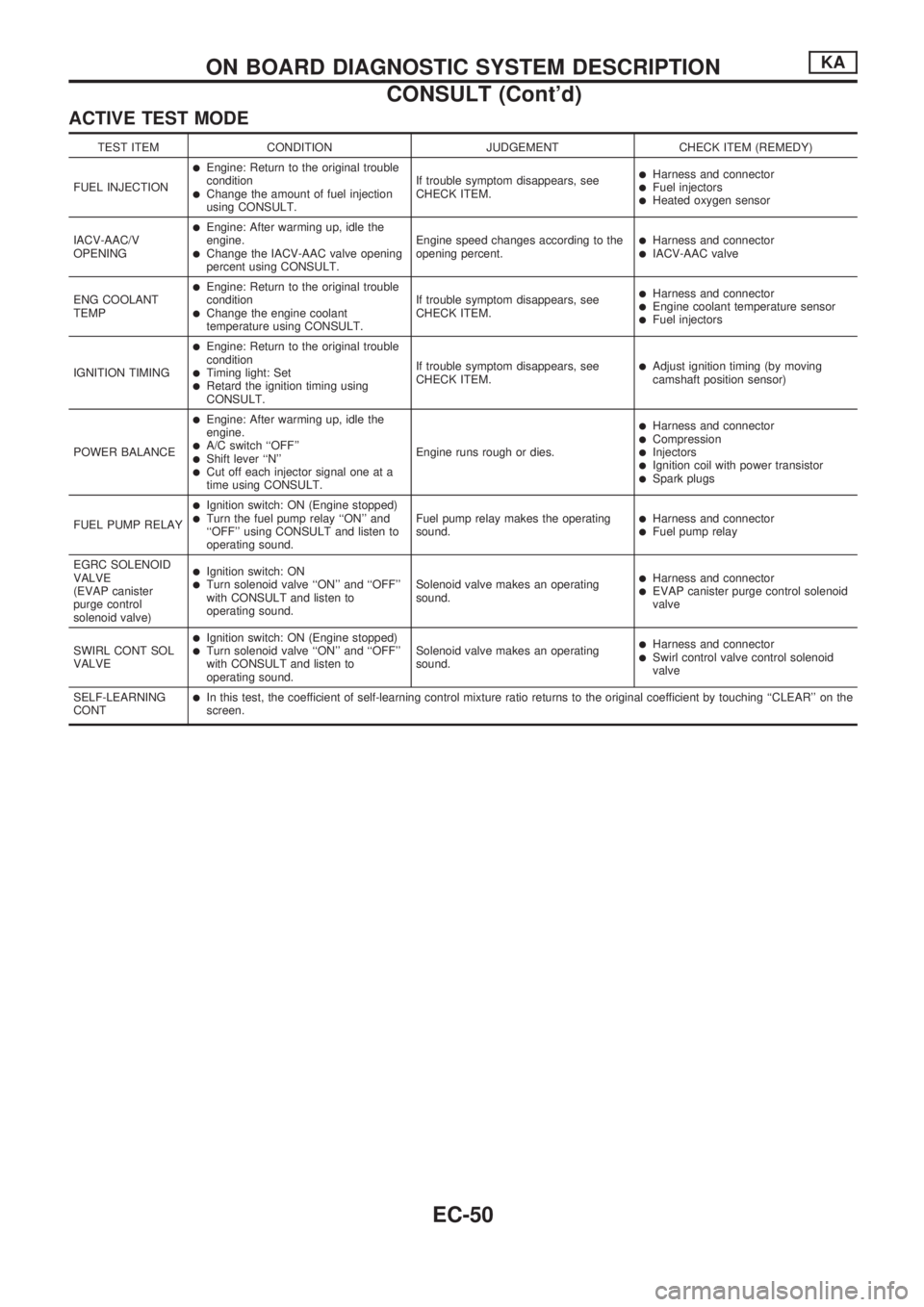
ACTIVE TEST MODE
TEST ITEM CONDITION JUDGEMENT CHECK ITEM (REMEDY)
FUEL INJECTION
lEngine: Return to the original trouble
condition
lChange the amount of fuel injection
using CONSULT.If trouble symptom disappears, see
CHECK ITEM.
lHarness and connectorlFuel injectorslHeated oxygen sensor
IACV-AAC/V
OPENING
lEngine: After warming up, idle the
engine.
lChange the IACV-AAC valve opening
percent using CONSULT.Engine speed changes according to the
opening percent.lHarness and connectorlIACV-AAC valve
ENG COOLANT
TEMP
lEngine: Return to the original trouble
condition
lChange the engine coolant
temperature using CONSULT.If trouble symptom disappears, see
CHECK ITEM.
lHarness and connectorlEngine coolant temperature sensorlFuel injectors
IGNITION TIMING
lEngine: Return to the original trouble
condition
lTiming light: SetlRetard the ignition timing using
CONSULT.If trouble symptom disappears, see
CHECK ITEM.
lAdjust ignition timing (by moving
camshaft position sensor)
POWER BALANCE
lEngine: After warming up, idle the
engine.
lA/C switch ``OFF''lShift lever ``N''lCut off each injector signal one at a
time using CONSULT.Engine runs rough or dies.
lHarness and connectorlCompressionlInjectorslIgnition coil with power transistorlSpark plugs
FUEL PUMP RELAY
lIgnition switch: ON (Engine stopped)lTurn the fuel pump relay ``ON'' and
``OFF'' using CONSULT and listen to
operating sound.Fuel pump relay makes the operating
sound.lHarness and connectorlFuel pump relay
EGRC SOLENOID
VALVE
(EVAP canister
purge control
solenoid valve)
lIgnition switch: ONlTurn solenoid valve ``ON'' and ``OFF''
with CONSULT and listen to
operating sound.Solenoid valve makes an operating
sound.lHarness and connectorlEVAP canister purge control solenoid
valve
SWIRL CONT SOL
VALVE
lIgnition switch: ON (Engine stopped)lTurn solenoid valve ``ON'' and ``OFF''
with CONSULT and listen to
operating sound.Solenoid valve makes an operating
sound.lHarness and connectorlSwirl control valve control solenoid
valve
SELF-LEARNING
CONT
lIn this test, the coefficient of self-learning control mixture ratio returns to the original coefficient by touching ``CLEAR'' on the
screen.
ON BOARD DIAGNOSTIC SYSTEM DESCRIPTIONKA
CONSULT (Cont'd)
EC-50
Page 214 of 1659
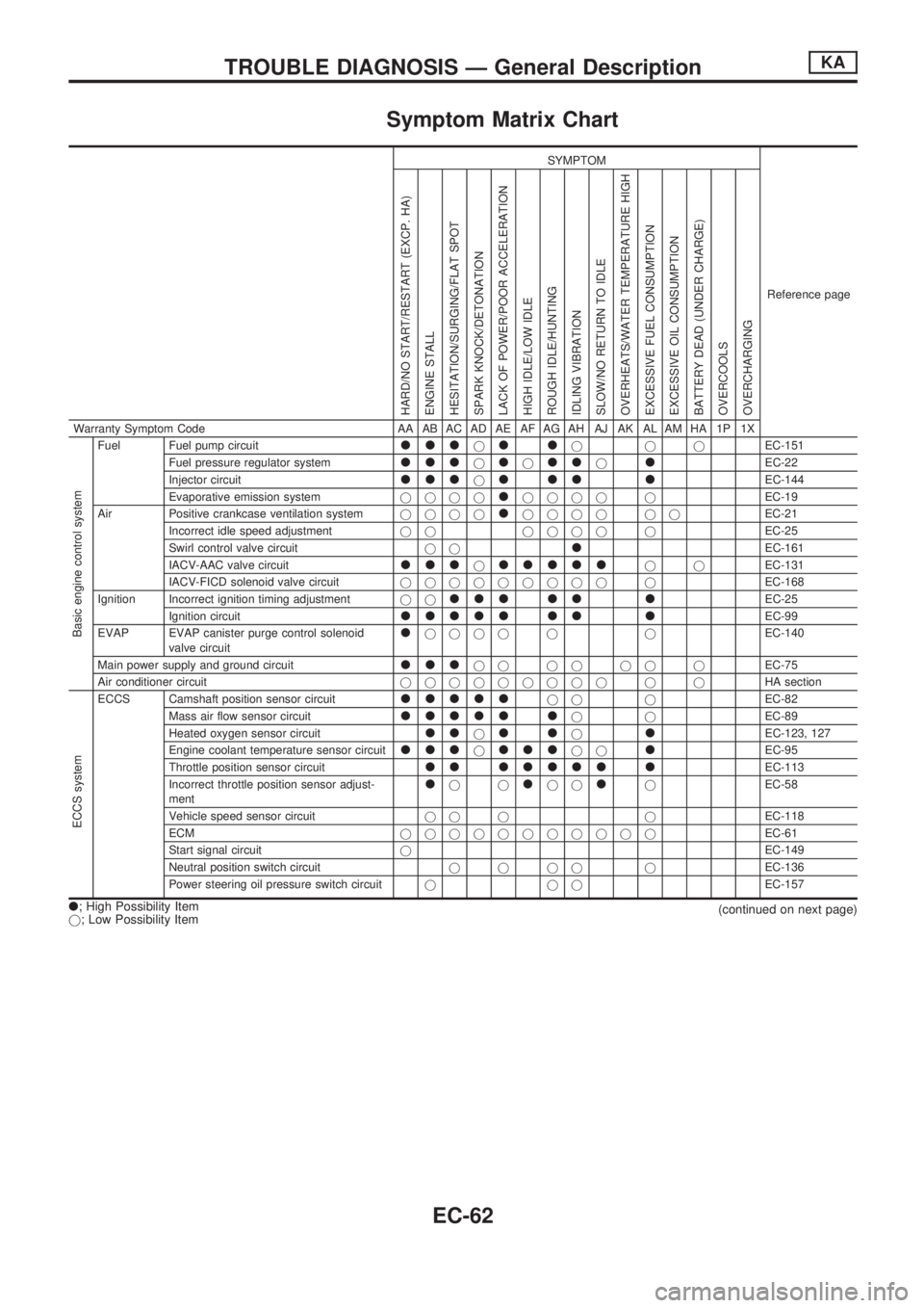
Symptom Matrix Chart
SYMPTOM
Reference page
HARD/NO START/RESTART (EXCP. HA)
ENGINE STALL
HESITATION/SURGING/FLAT SPOT
SPARK KNOCK/DETONATION
LACK OF POWER/POOR ACCELERATION
HIGH IDLE/LOW IDLE
ROUGH IDLE/HUNTING
IDLING VIBRATION
SLOW/NO RETURN TO IDLE
OVERHEATS/WATER TEMPERATURE HIGH
EXCESSIVE FUEL CONSUMPTION
EXCESSIVE OIL CONSUMPTION
BATTERY DEAD (UNDER CHARGE)
OVERCOOLS
OVERCHARGING
Warranty Symptom Code AA AB AC AD AE AF AG AH AJ AK AL AM HA 1P 1X
Basic engine control system
Fuel Fuel pump circuitllljlljjjEC-151
Fuel pressure regulator system
llljljlljlEC-22
Injector circuit
llljlll lEC-144
Evaporative emission systemjjjj
ljjjj jEC-19
Air Positive crankcase ventilation systemjjjj
ljjjj jjEC-21
Incorrect idle speed adjustmentjj jjjj jEC-25
Swirl control valve circuitjj
lEC-161
IACV-AAC valve circuit
llljllllljjEC-131
IACV-FICD solenoid valve circuitjjjjjjjjj jEC-168
Ignition Incorrect ignition timing adjustmentjj
lll ll lEC-25
Ignition circuit
lllll ll lEC-99
EVAP EVAP canister purge control solenoid
valve circuit
ljjjj j jEC-140
Main power supply and ground circuit
llljj jj jj jEC-75
Air conditioner circuitjjjjjjjjj j jHA section
ECCS system
ECCS Camshaft position sensor circuitllllljj jEC-82
Mass air flow sensor circuit
lllll ljjEC-89
Heated oxygen sensor circuit
lljlljlEC-123, 127
Engine coolant temperature sensor circuit
llljllljjlEC-95
Throttle position sensor circuit
ll lllll lEC-113
Incorrect throttle position sensor adjust-
ment
ljjljjljEC-58
Vehicle speed sensor circuitjj j jEC-118
ECMjjjjjjjjjjjEC-61
Start signal circuitjEC-149
Neutral position switch circuitjjjj jEC-136
Power steering oil pressure switch circuitjjjEC-157
l; High Possibility Item
j; Low Possibility Item(continued on next page)
TROUBLE DIAGNOSIS Ð General DescriptionKA
EC-62
Page 216 of 1659
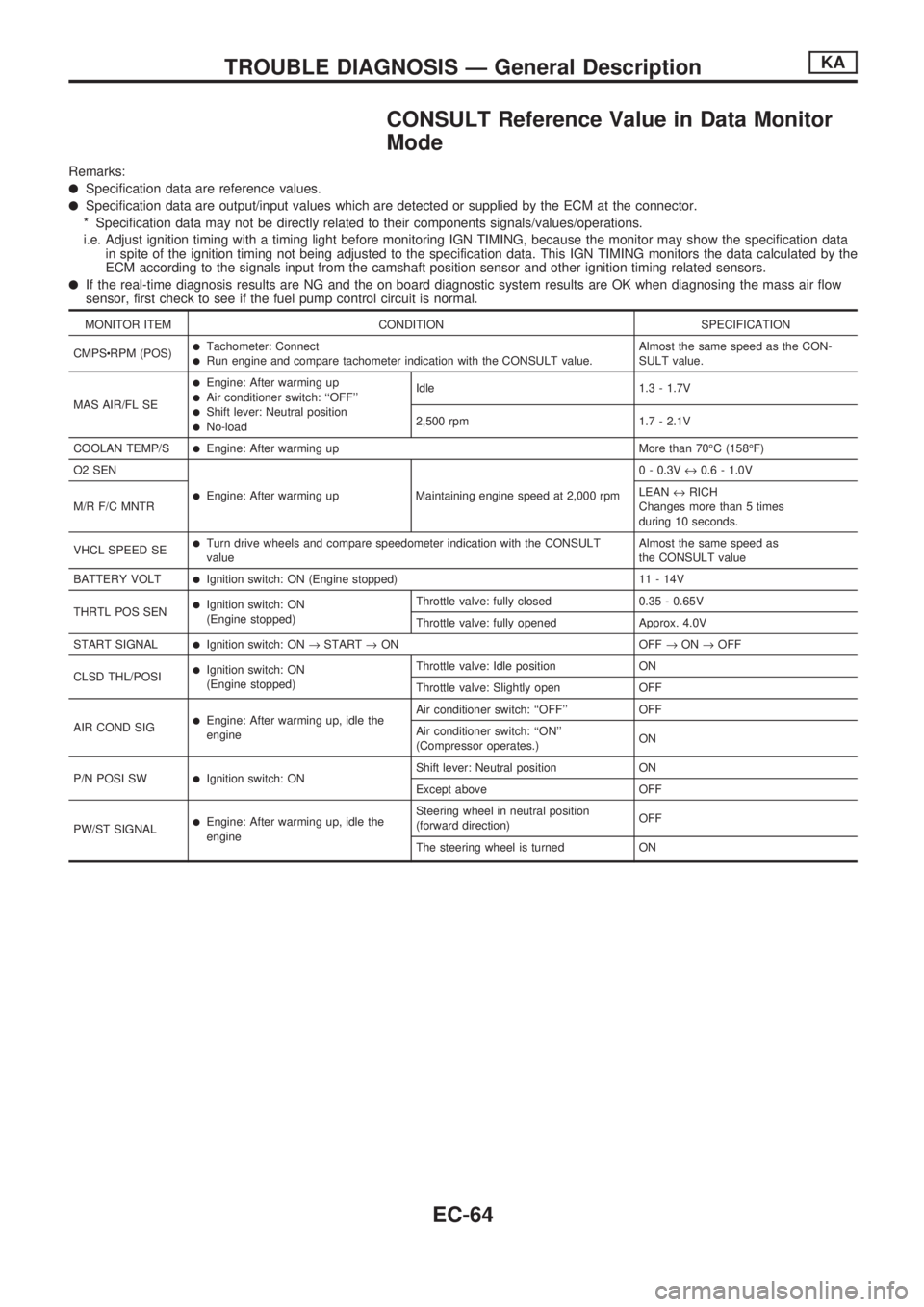
CONSULT Reference Value in Data Monitor
Mode
Remarks:
lSpecification data are reference values.
lSpecification data are output/input values which are detected or supplied by the ECM at the connector.
* Specification data may not be directly related to their components signals/values/operations.
i.e. Adjust ignition timing with a timing light before monitoring IGN TIMING, because the monitor may show the specification data
in spite of the ignition timing not being adjusted to the specification data. This IGN TIMING monitors the data calculated by the
ECM according to the signals input from the camshaft position sensor and other ignition timing related sensors.
lIf the real-time diagnosis results are NG and the on board diagnostic system results are OK when diagnosing the mass air flow
sensor, first check to see if the fuel pump control circuit is normal.
MONITOR ITEM CONDITION SPECIFICATION
CMPScRPM (POS)
lTachometer: ConnectlRun engine and compare tachometer indication with the CONSULT value.Almost the same speed as the CON-
SULT value.
MAS AIR/FL SE
lEngine: After warming uplAir conditioner switch: ``OFF''lShift lever: Neutral positionlNo-loadIdle 1.3 - 1.7V
2,500 rpm 1.7 - 2.1V
COOLAN TEMP/S
lEngine: After warming up More than 70ÉC (158ÉF)
O2 SEN
lEngine: After warming up Maintaining engine speed at 2,000 rpm0 - 0.3V«0.6 - 1.0V
M/R F/C MNTRLEAN«RICH
Changes more than 5 times
during 10 seconds.
VHCL SPEED SE
lTurn drive wheels and compare speedometer indication with the CONSULT
valueAlmost the same speed as
the CONSULT value
BATTERY VOLT
lIgnition switch: ON (Engine stopped) 11 - 14V
THRTL POS SEN
lIgnition switch: ON
(Engine stopped)Throttle valve: fully closed 0.35 - 0.65V
Throttle valve: fully opened Approx. 4.0V
START SIGNAL
lIgnition switch: ON®START®ON OFF®ON®OFF
CLSD THL/POSI
lIgnition switch: ON
(Engine stopped)Throttle valve: Idle position ON
Throttle valve: Slightly open OFF
AIR COND SIG
lEngine: After warming up, idle the
engineAir conditioner switch: ``OFF'' OFF
Air conditioner switch: ``ON''
(Compressor operates.)ON
P/N POSI SW
lIgnition switch: ONShift lever: Neutral position ON
Except above OFF
PW/ST SIGNAL
lEngine: After warming up, idle the
engineSteering wheel in neutral position
(forward direction)OFF
The steering wheel is turned ON
TROUBLE DIAGNOSIS Ð General DescriptionKA
EC-64