wiring NISSAN PICK-UP 1998 Repair Manual
[x] Cancel search | Manufacturer: NISSAN, Model Year: 1998, Model line: PICK-UP, Model: NISSAN PICK-UP 1998Pages: 1659, PDF Size: 53.39 MB
Page 4 of 1659
How to Perform Trouble Diagnoses for Quick
and Accurate Repair ............................................ 38
Preliminary Check ................................................ 39
Component Parts and Harness Connector
Location................................................................ 40
Schematic/2WD Models....................................... 41
Wiring Diagram - ABS -/2WD LHD Models ......... 42
Wiring Diagram - ABS -/2WD RHD Models ........ 45
Schematic/4WD Models....................................... 48
Wiring Diagram - ABS -/4WD Models ................. 49
Self-diagnosis....................................................... 53
CONSULT ............................................................ 56
CONSULT Inspection Procedure......................... 57
Ground Circuit Check .......................................... 62
TROUBLE DIAGNOSES FOR
SELF-DIAGNOSTIC ITEMS.................................... 63
Diagnostic Procedure 1
(Wheel sensor or rotor)........................................ 63
Diagnostic Procedure 2 (ABS actuator
solenoid valve and solenoid valve relay)............. 65
Diagnostic Procedure 3 (Motor relay or motor) ... 67
Diagnostic Procedure 4 (Low voltage) ................ 69Diagnostic Procedure 5 (G sensor) ..................... 70
Diagnostic Procedure 6 (Control unit) ................. 71
TROUBLE DIAGNOSES FOR SYMPTOMS........... 72
Diagnostic Procedure 7
(ABS works frequently.) ....................................... 72
Diagnostic Procedure 8
(Unexpected pedal action) ................................... 73
Diagnostic Procedure 9
(Long stopping distance) ..................................... 73
Diagnostic Procedure 10
(ABS does not work.)........................................... 74
Diagnostic Procedure 11
(Pedal vibration and noise) .................................. 74
Diagnostic Procedure 12 (Warning lamp does
not come on when ignition switch is turned
ON.)...................................................................... 75
Diagnostic Procedure 13 (Warning lamp stays
on when ignition switch is turned ON.)................ 77
SERVICE DATA AND SPECIFICATIONS (SDS)... 78
General Specifications ......................................... 78
Inspection and Adjustment .................................. 80
When you read wiring diagrams:
lRead GI section, ``HOW TO READ WIRING DIAGRAMS''.
lSee EL section, ``POWER SUPPLY ROUTING'' for power distribution circuit.
When you perform trouble diagnoses, read GI section, ``HOW TO FOLLOW FLOW
CHART IN TROUBLE DIAGNOSES'' and ``HOW TO PERFORM EFFICIENT DIAGNOSIS
FOR AN ELECTRICAL INCIDENT''.
Page 5 of 1659
Supplemental Restraint System (SRS) ``AIR
BAG'' (4WD models)
The Supplemental Restraint System ``AIR BAG'', used along with a seat belt, helps to reduce the risk or
severity of injury to the driver in a frontal collision. The Supplemental Restraint System consists of air bag
module (located in the center of the steering wheel), a diagnosis sensor unit, warning lamp, wiring harness
and spiral cable. Information necessary to service the system safely is included in theRS sectionof this
Service Manual.
WARNING:
lTo avoid rendering the SRS inoperative, which could increase the risk of personal injury or death
in the event of a collision which would result in air bag inflation, all maintenance must be per-
formed by an authorized NISSAN dealer.
lImproper maintenance, including incorrect removal and installation of the SRS, can lead to per-
sonal injury caused by unintentional activation of the system.
lDo not use electrical test equipment on any circuit related to the SRS unless instructed to in this
Service Manual. SRS wiring harnesses are covered with yellow insulation either just before the
harness connectors or for the complete harness, for easy identification.
Supplemental Restraint System (SRS) ``AIR
BAG'' (2WD models)
The Supplemental Restraint System ``AIR BAG'', used along with a seat belt, helps to reduce the risk or
severity of injury to the driver in a frontal collision. The Supplemental Restraint System consists of an air
bag module (located in the center of the steering wheel), a diagnosis sensor unit, warning lamp and spiral
cable. Information necessary to service the system safely is included in theRS sectionof this Service
Manual.
WARNING:
lTo avoid rendering the SRS inoperative, which could increase the risk of personal injury or death
in the event of a collision which would result in air bag inflation, all maintenance must be per-
formed by an authorized NISSAN dealer.
lImproper maintenance, including incorrect removal and installation of the SRS, can lead to per-
sonal injury caused by unintentional activation of the system.
lDo not use electrical test equipment on any circuit related to the SRS.
Precautions for Brake System
lUse brake fluid DOT 3 or DOT 4*1.
lNever reuse drained brake fluid.
lBe careful not to splash brake fluid on painted areas; it
may cause paint damage. If brake fluid is splashed on
painted areas, wash it away with water immediately.
lTo clean master cylinder parts, disc brake caliper parts
or wheel cylinder parts, use clean brake fluid.
lNever use mineral oils such as gasoline or kerosene.
They will ruin rubber parts of the hydraulic system.
lUse flare nut wrench when removing and installing brake
tubes.
lAlways torque brake lines when installing.
WARNING:
lClean brakes with a vacuum dust collector to minimize
the hazard of airborne materials.
*1: Refer to MA section (``Fluids and Lubricants'', ``RECOM-
MENDED FLUIDS AND LUBRICANTS'').
SBR820BA
PRECAUTIONS AND PREPARATION
BR-1
Page 42 of 1659
How to Perform Trouble Diagnoses for Quick
and Accurate Repair
INTRODUCTION
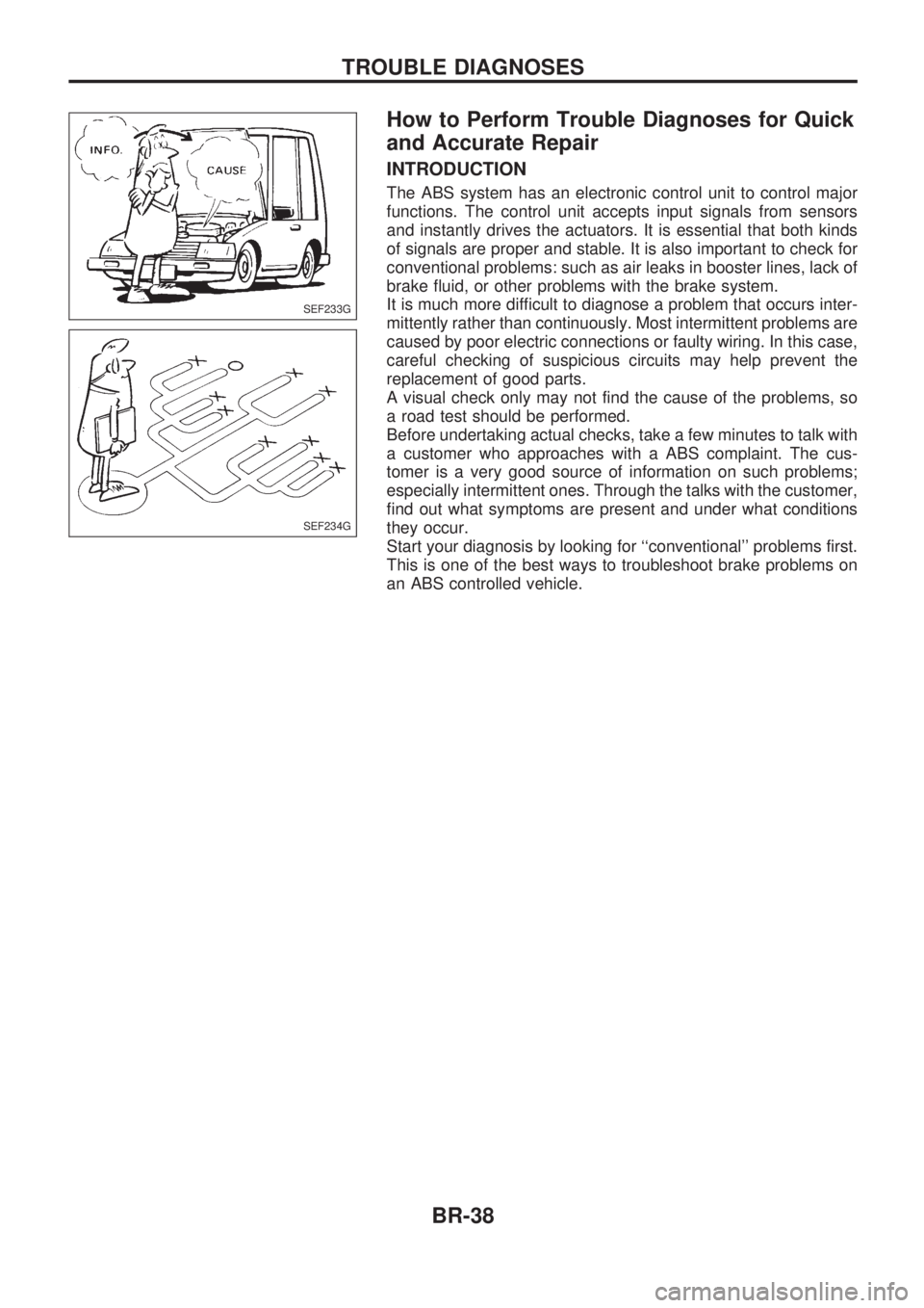
The ABS system has an electronic control unit to control major
functions. The control unit accepts input signals from sensors
and instantly drives the actuators. It is essential that both kinds
of signals are proper and stable. It is also important to check for
conventional problems: such as air leaks in booster lines, lack of
brake fluid, or other problems with the brake system.
It is much more difficult to diagnose a problem that occurs inter-
mittently rather than continuously. Most intermittent problems are
caused by poor electric connections or faulty wiring. In this case,
careful checking of suspicious circuits may help prevent the
replacement of good parts.
A visual check only may not find the cause of the problems, so
a road test should be performed.
Before undertaking actual checks, take a few minutes to talk with
a customer who approaches with a ABS complaint. The cus-
tomer is a very good source of information on such problems;
especially intermittent ones. Through the talks with the customer,
find out what symptoms are present and under what conditions
they occur.
Start your diagnosis by looking for ``conventional'' problems first.
This is one of the best ways to troubleshoot brake problems on
an ABS controlled vehicle.
SEF233G
SEF234G
TROUBLE DIAGNOSES
BR-38
Page 46 of 1659
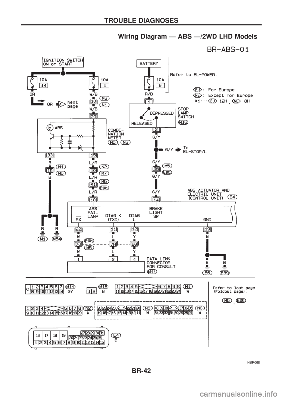
Wiring Diagram Ð ABS Ð/2WD LHD Models
HBR068
TROUBLE DIAGNOSES
BR-42
Page 47 of 1659
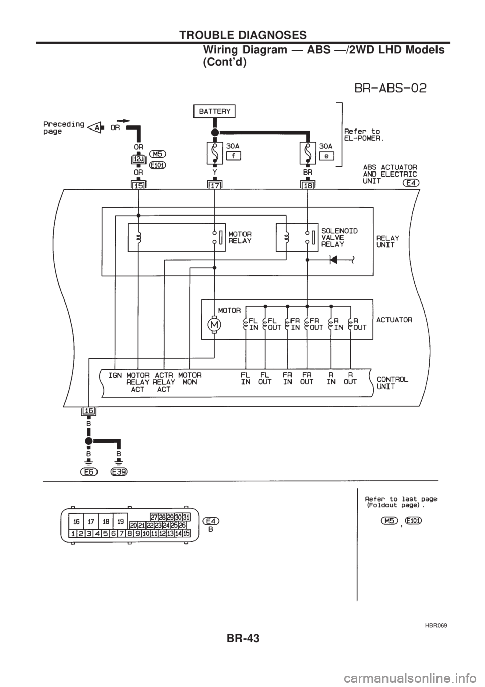
HBR069
TROUBLE DIAGNOSES
Wiring Diagram Ð ABS Ð/2WD LHD Models
(Cont'd)
BR-43
Page 48 of 1659
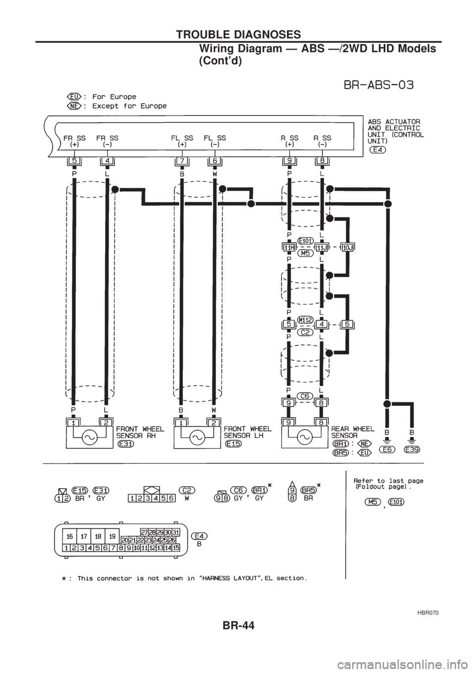
HBR070
TROUBLE DIAGNOSES
Wiring Diagram Ð ABS Ð/2WD LHD Models
(Cont'd)
BR-44
Page 49 of 1659
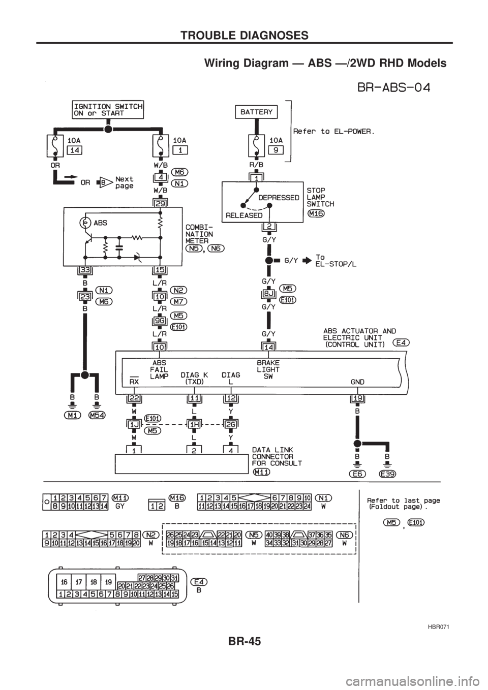
Wiring Diagram Ð ABS Ð/2WD RHD Models
HBR071
TROUBLE DIAGNOSES
BR-45
Page 50 of 1659
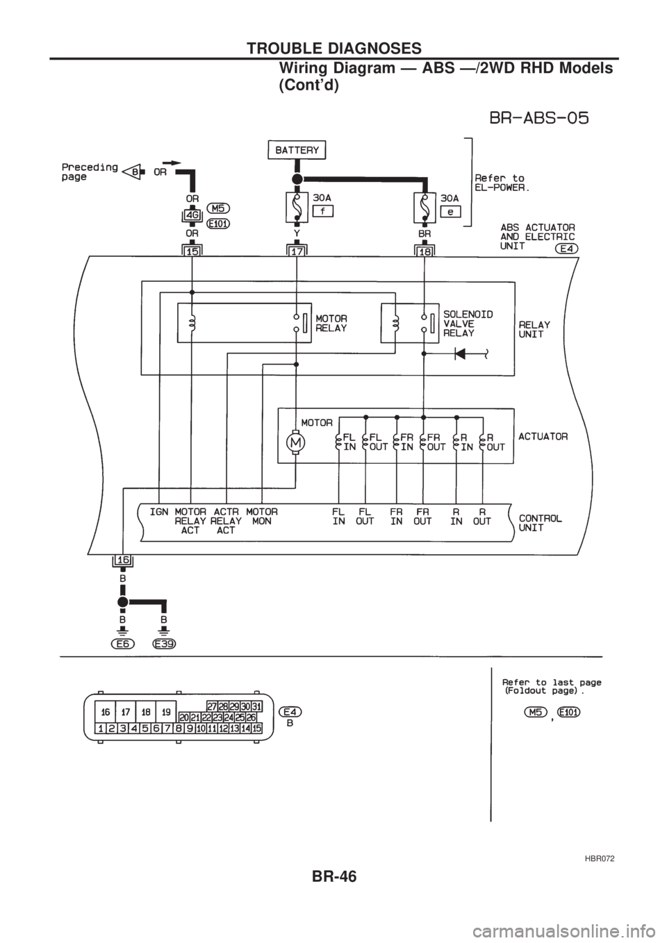
HBR072
TROUBLE DIAGNOSES
Wiring Diagram Ð ABS Ð/2WD RHD Models
(Cont'd)
BR-46
Page 51 of 1659
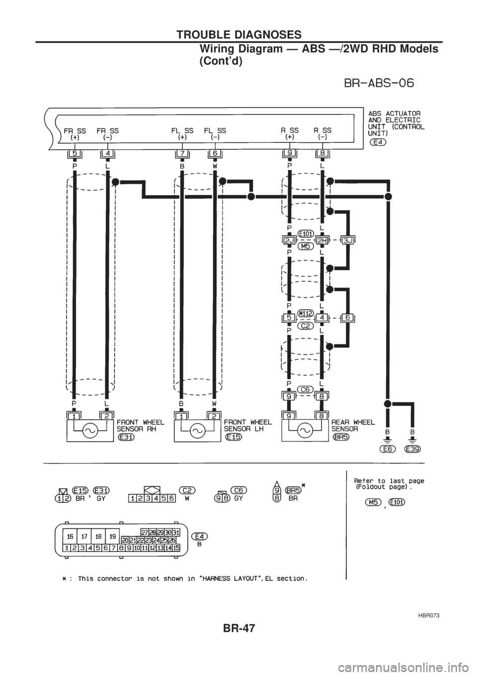
HBR073
TROUBLE DIAGNOSES
Wiring Diagram Ð ABS Ð/2WD RHD Models
(Cont'd)
BR-47
Page 53 of 1659
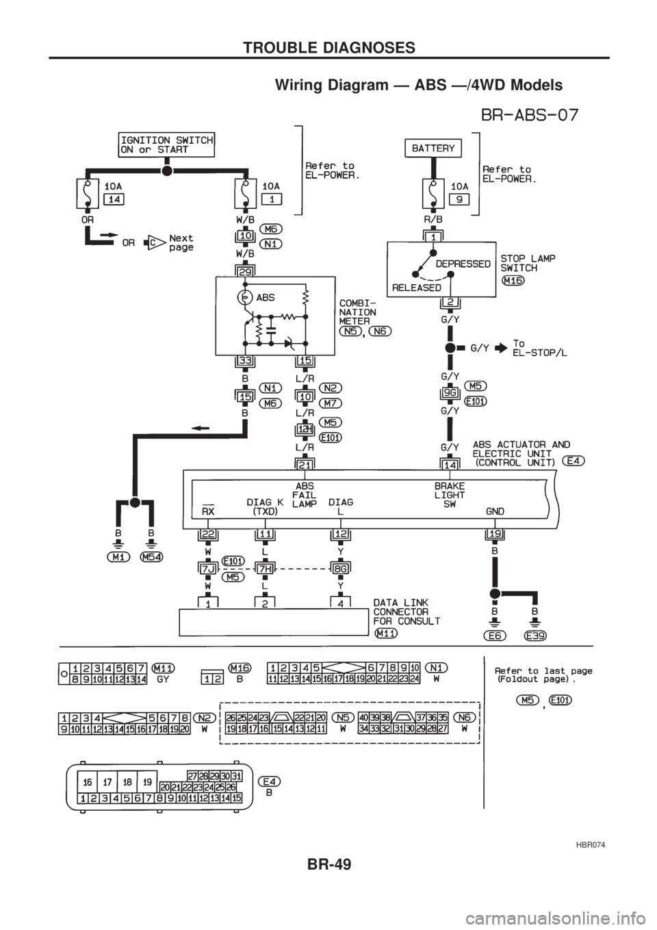
Wiring Diagram Ð ABS Ð/4WD Models
HBR074
TROUBLE DIAGNOSES
BR-49