light NISSAN PICK-UP 1999 Repair Manual
[x] Cancel search | Manufacturer: NISSAN, Model Year: 1999, Model line: PICK-UP, Model: NISSAN PICK-UP 1999Pages: 666, PDF Size: 16.21 MB
Page 80 of 666
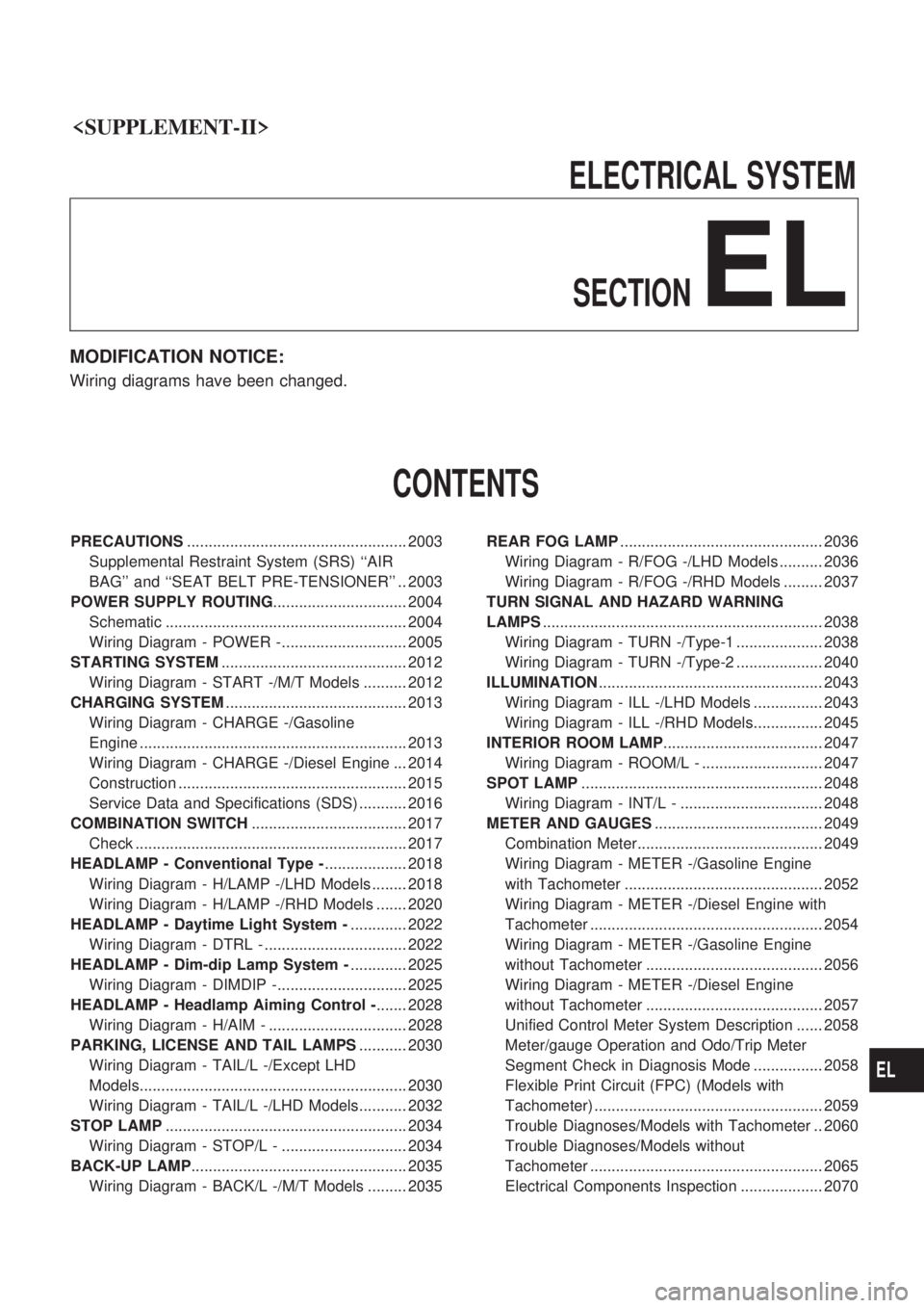
ELECTRICALSYSTEM
SECTION
EL
MODIFICATION NOTICE:
Wiring diagrams have been changed.
CONTENTS
PRECAUTIONS ................................................... 2003
Supplemental Restraint System (SRS) ``AIR
BAG'' and ``SEAT BELT PRE-TENSIONER'' .. 2003
POWER SUPPLY ROUTING ............................... 2004
Schematic ........................................................ 2004
Wiring Diagram - POWER -............................. 2005
STARTING SYSTEM ........................................... 2012
Wiring Diagram - START -/M/T Models .......... 2012
CHARGING SYSTEM .......................................... 2013
Wiring Diagram - CHARGE -/Gasoline
Engine .............................................................. 2013
Wiring Diagram - CHARGE -/Diesel Engine ... 2014
Construction ..................................................... 2015
Service Data and Specifications (SDS) ........... 2016
COMBINATION SWITCH .................................... 2017
Check ............................................................... 2017
HEADLAMP - Conventional Type - ................... 2018
Wiring Diagram - H/LAMP -/LHD Models ........ 2018
Wiring Diagram - H/LAMP -/RHD Models ....... 2020
HEADLAMP - Daytime Light System - ............. 2022
Wiring Diagram - DTRL - ................................. 2022
HEADLAMP - Dim-dip Lamp System - ............. 2025
Wiring Diagram - DIMDIP -.............................. 2025
HEADLAMP - Headlamp Aiming Control - ....... 2028
Wiring Diagram - H/AIM - ................................ 2028
PARKING, LICENSE AND TAIL LAMPS ........... 2030
Wiring Diagram - TAIL/L -/Except LHD
Models.............................................................. 2030
Wiring Diagram - TAIL/L -/LHD Models........... 2032
STOP LAMP ........................................................ 2034
Wiring Diagram - STOP/L - ............................. 2034
BACK-UP LAMP .................................................. 2035
Wiring Diagram - BACK/L -/M/T Models ......... 2035 REAR FOG LAMP
............................................... 2036
Wiring Diagram - R/FOG -/LHD Models .......... 2036
Wiring Diagram - R/FOG -/RHD Models ......... 2037
TURN SIGNAL AND HAZARD WARNING
LAMPS ................................................................. 2038
Wiring Diagram - TURN -/Type-1 .................... 2038
Wiring Diagram - TURN -/Type-2 .................... 2040
ILLUMINATION .................................................... 2043
Wiring Diagram - ILL -/LHD Models ................ 2043
Wiring Diagram - ILL -/RHD Models................ 2045
INTERIOR ROOM LAMP ..................................... 2047
Wiring Diagram - ROOM/L - ............................ 2047
SPOT LAMP ........................................................ 2048
Wiring Diagram - INT/L - ................................. 2048
METER AND GAUGES ....................................... 2049
Combination Meter........................................... 2049
Wiring Diagram - METER -/Gasoline Engine
with Tachometer .............................................. 2052
Wiring Diagram - METER -/Diesel Engine with
Tachometer ...................................................... 2054
Wiring Diagram - METER -/Gasoline Engine
without Tachometer ......................................... 2056
Wiring Diagram - METER -/Diesel Engine
without Tachometer ......................................... 2057
Unified Control Meter System Description ...... 2058
Meter/gauge Operation and Odo/Trip Meter
Segment Check in Diagnosis Mode ................ 2058
Flexible Print Circuit (FPC) (Models with
Tachometer) ..................................................... 2059
Trouble Diagnoses/Models with Tachometer .. 2060
Trouble Diagnoses/Models without
Tachometer ...................................................... 2065
Electrical Components Inspection ................... 2070
EL
Page 81 of 666
WARNING LAMPS.............................................. 2072
Schematic ........................................................ 2072
Wiring Diagram - WARN -/Gasoline Engine.... 2073
Wiring Diagram - WARN -/Diesel Engine ........ 2078
Electrical Components Inspection ................... 2083
Wiring Diagram - CHIME -/LHD Models.......... 2084
Wiring Diagram - CHIME -/RHD Models ......... 2085
FRONT WIPER AND WASHER.......................... 2086
Wiring Diagram - WIPER -/LHD Models with
Intermittent ....................................................... 2086
Wiring Diagram - WIPER -/LHD Models
without Intermittent........................................... 2087
Wiring Diagram - WIPER -/RHD M/T Models
with Intermittent................................................ 2088
Wiring Diagram - WIPER -/RHD Models
without Intermittent........................................... 2090
HEADLAMP WASHER........................................ 2092
Wiring Diagram - HLC - ................................... 2092
HORN................................................................... 2093
Wiring Diagram - HORN -................................ 2093
CIGARETTE LIGHTER........................................ 2094
Wiring Diagram - CIGAR - ............................... 2094
CLOCK................................................................. 2095
Wiring Diagram - CLOCK - .............................. 2095
REAR WINDOW DEFOGGER AND MIRROR
DEFOGGER......................................................... 2096
Wiring Diagram - DEF -/LHD Models .............. 2096
Wiring Diagram - DEF -/RHD Models ............. 2097
Electrical Components Inspection ................... 2098
AUDIO.................................................................. 2099
Wiring Diagram - AUDIO -/LHD Models
Type-2 .............................................................. 2099
Wiring Diagram - AUDIO -/LHD Models
Type-3 .............................................................. 2100
Wiring Diagram - AUDIO -/RHD Models ......... 2102
AUDIO ANTENNA............................................... 2103
Power Antenna/Wiring Diagram - P/ANT - ...... 2103
POWER DOOR MIRROR.................................... 2104
Wiring Diagram - MIRROR -/LHD Models....... 2104
Wiring Diagram - MIRROR -/RHD Models ...... 2105
HEATED SEAT.................................................... 2106
Wiring Diagram - H/SEAT - ............................. 2106
POWER WINDOW............................................... 2108
Schematic/Without Interruption Detection
Function ........................................................... 2108Wiring Diagram - WINDOW -/Without
Interruption Detection Function........................ 2109
Trouble Diagnoses/Without Interruption
Detection Function ........................................... 2113
System Description/With Interruption Detection
Function ........................................................... 2114
Schematic/With Interruption Detection
Function ........................................................... 2115
Wiring Diagram - WINDOW -/With Interruption
Detection Function ........................................... 2116
Trouble Diagnoses/With Interruption Detection
Function ........................................................... 2120
POWER DOOR LOCK......................................... 2122
System Description .......................................... 2122
Wiring Diagram - D/LOCK - ............................. 2123
Trouble Diagnosis ............................................ 2125
MULTI-REMOTE CONTROL SYSTEM............... 2129
System Description .......................................... 2129
Schematic ........................................................ 2130
Wiring Diagram - MULTI - ............................... 2131
Trouble Diagnoses ........................................... 2135
ID Code Entry Procedure ................................ 2139
NATS (Nissan Anti-Theft System)/Models with
KA24E.................................................................. 2140
Wiring Diagram - NATS -................................. 2140
NATS (Nissan Anti-Theft System)/Diesel
engine.................................................................. 2141
Wiring Diagram - NATS -/LHD Models............ 2141
Wiring Diagram - NATS -/RHD Models ........... 2142
LOCATION OF ELECTRICAL UNITS................. 2143
Engine Compartment ....................................... 2143
Passenger Compartment ................................. 2144
HARNESS LAYOUT............................................ 2146
Main Harness ................................................... 2146
Engine Room Harness..................................... 2152
Engine Control Harness................................... 2160
Alternator Harness ........................................... 2164
Instrument Harness.......................................... 2165
Room Lamp Harness/LHD Models .................. 2166
Room Lamp Harness/RHD Models ................. 2167
Chassis Harness and Tail Harness ................. 2168
Front Door Harness (LH side) ......................... 2169
Front Door Harness (RH side)......................... 2170
WIRING DIAGRAM CODES (CELL CODES)..... 2171
WIRING DIAGRAM REFERENCE CHART
COOLING FAN .......................................................................................................... LC SECTION
ECCS, IGNITION SYSTEM, QUICK-GLOW SYSTEM, FUEL HEATER SYSTEM .. EC SECTION
ANTI-LOCK BRAKE SYSTEM .................................................................................. BR SECTION
SRS ``AIR BAG'' ........................................................................................................ RS SECTION
HEATER AND AIR CONDITIONER .......................................................................... HA SECTION
EL-2002
Page 101 of 666
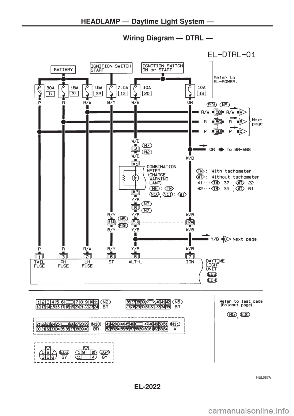
Wiring Diagram Ð DTRL Ð
HEL687A
HEADLAMP Ð Daytime Light System Ð
EL-2022
Page 102 of 666
HEL688A
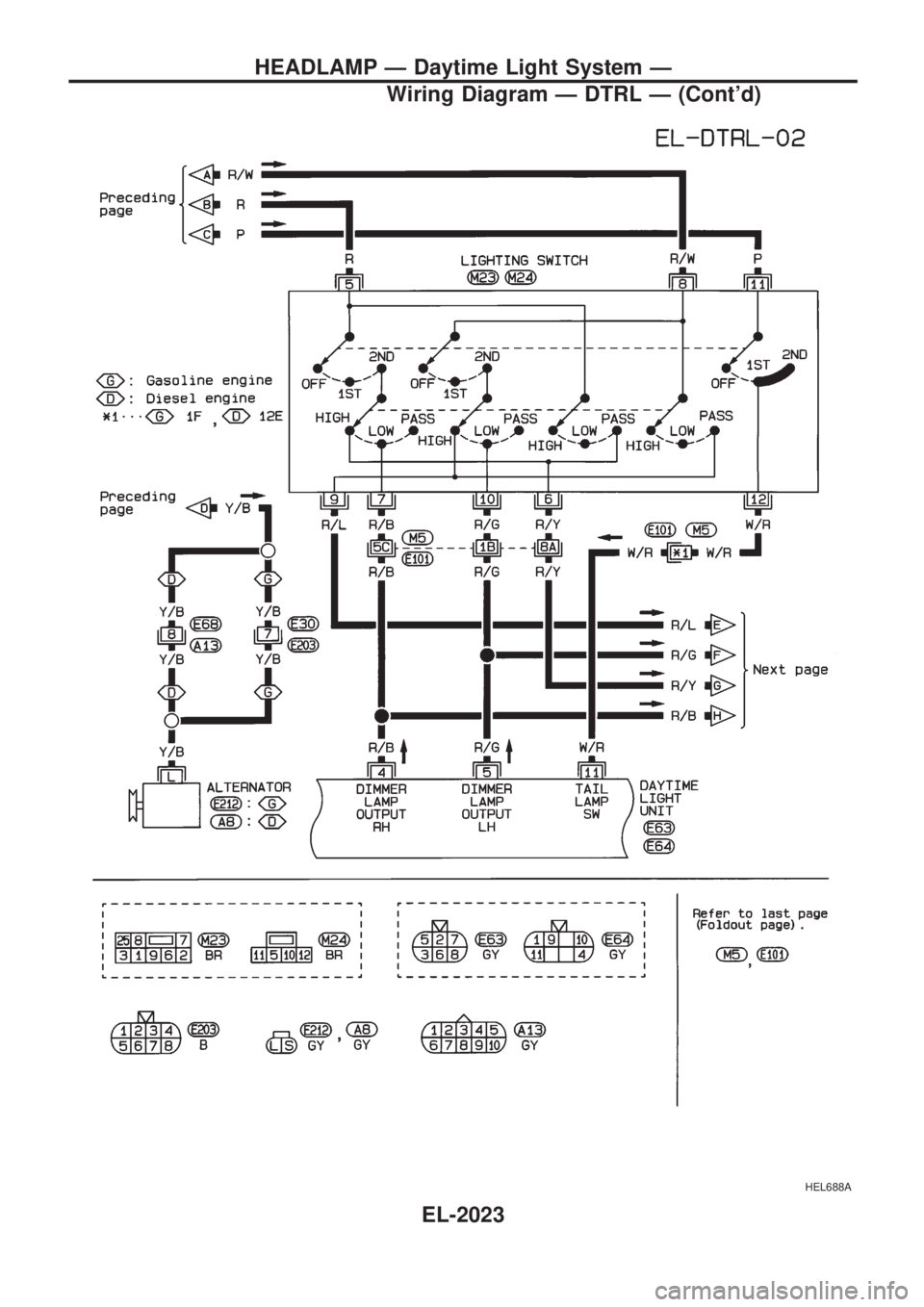
HEADLAMP Ð Daytime Light System Ð
Wiring Diagram Ð DTRL Ð (Cont'd)
EL-2023
Page 103 of 666
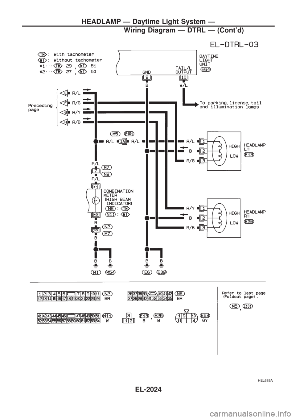
HEL689A
HEADLAMP Ð Daytime Light System Ð
Wiring Diagram Ð DTRL Ð (Cont'd)
EL-2024
Page 162 of 666
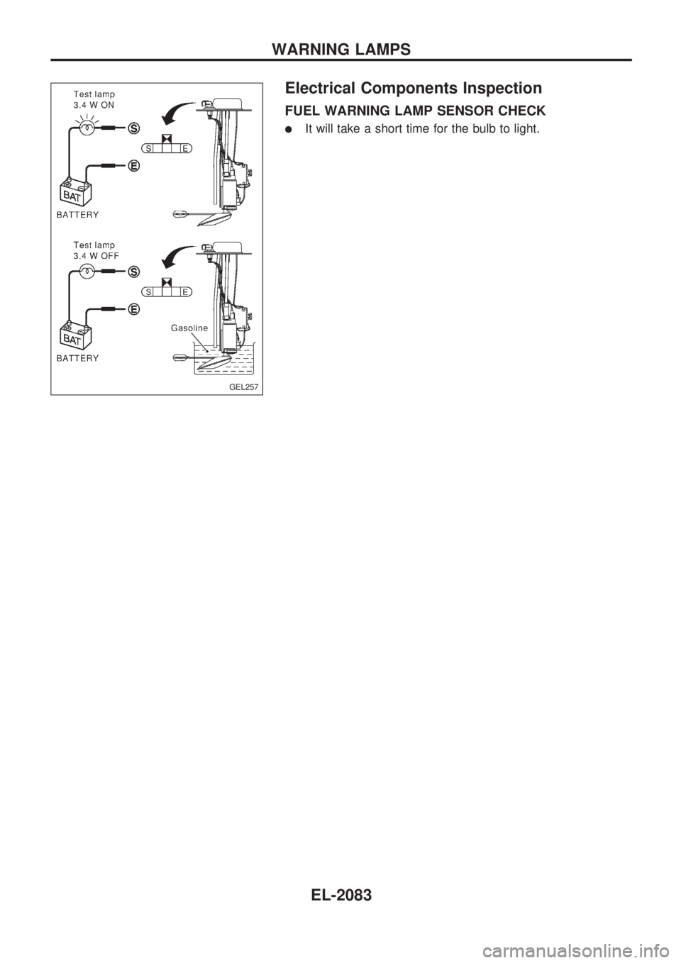
Electrical Components Inspection
FUEL WARNING LAMP SENSOR CHECK
lIt will take a short time for the bulb to light.
GEL257
WARNING LAMPS
EL-2083
Page 163 of 666
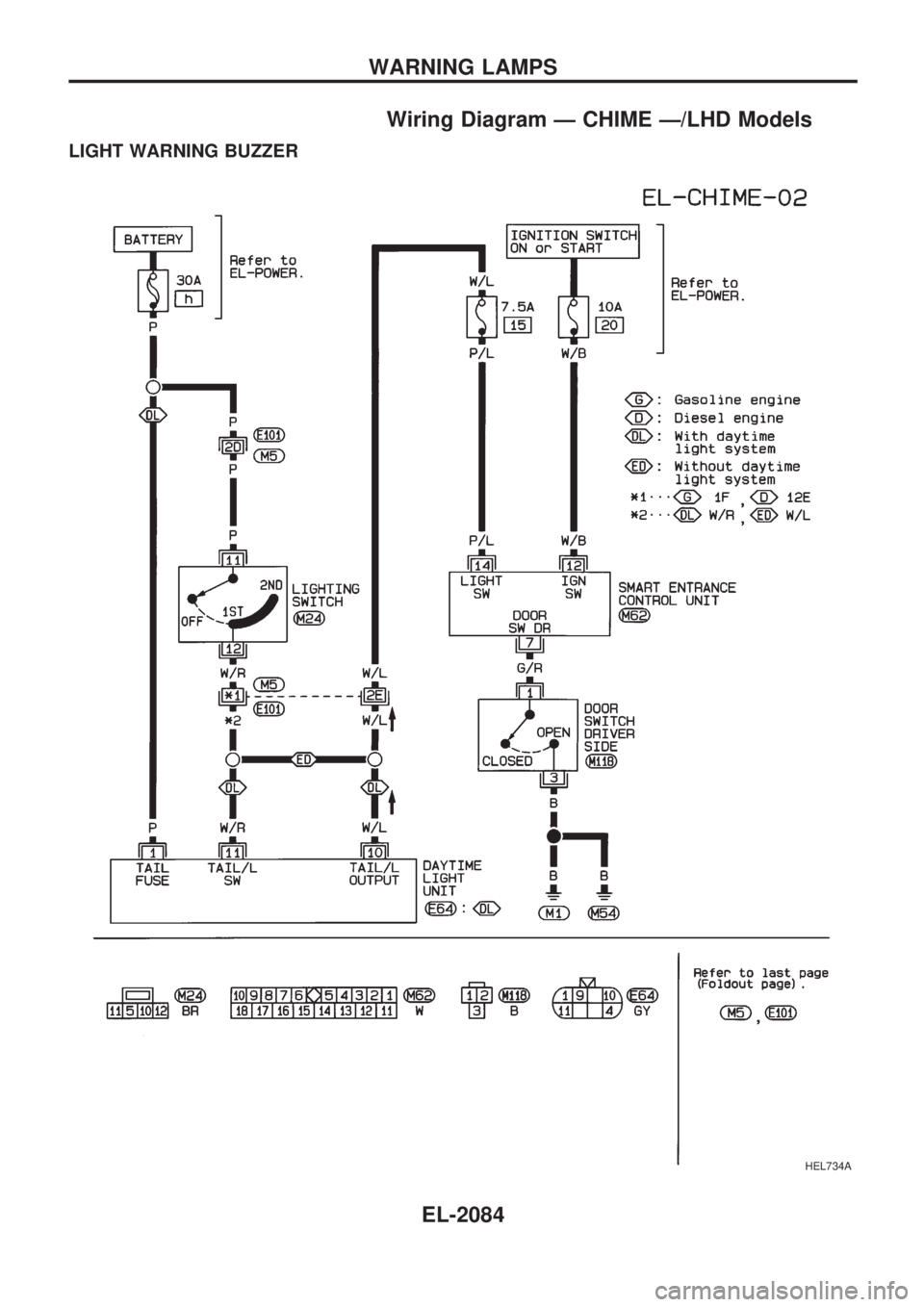
Wiring Diagram Ð CHIME Ð/LHD Models
LIGHT WARNING BUZZER
HEL734A
WARNING LAMPS
EL-2084
Page 164 of 666
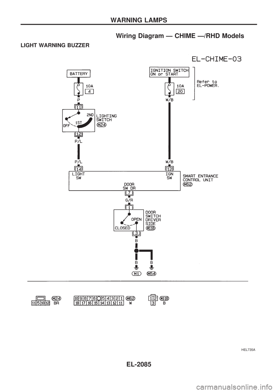
Wiring Diagram Ð CHIME Ð/RHD Models
LIGHT WARNING BUZZER
HEL735A
WARNING LAMPS
EL-2085
Page 173 of 666
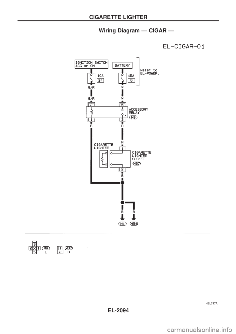
Wiring Diagram Ð CIGAR Ð
HEL747A
CIGARETTE LIGHTER
EL-2094
Page 250 of 666
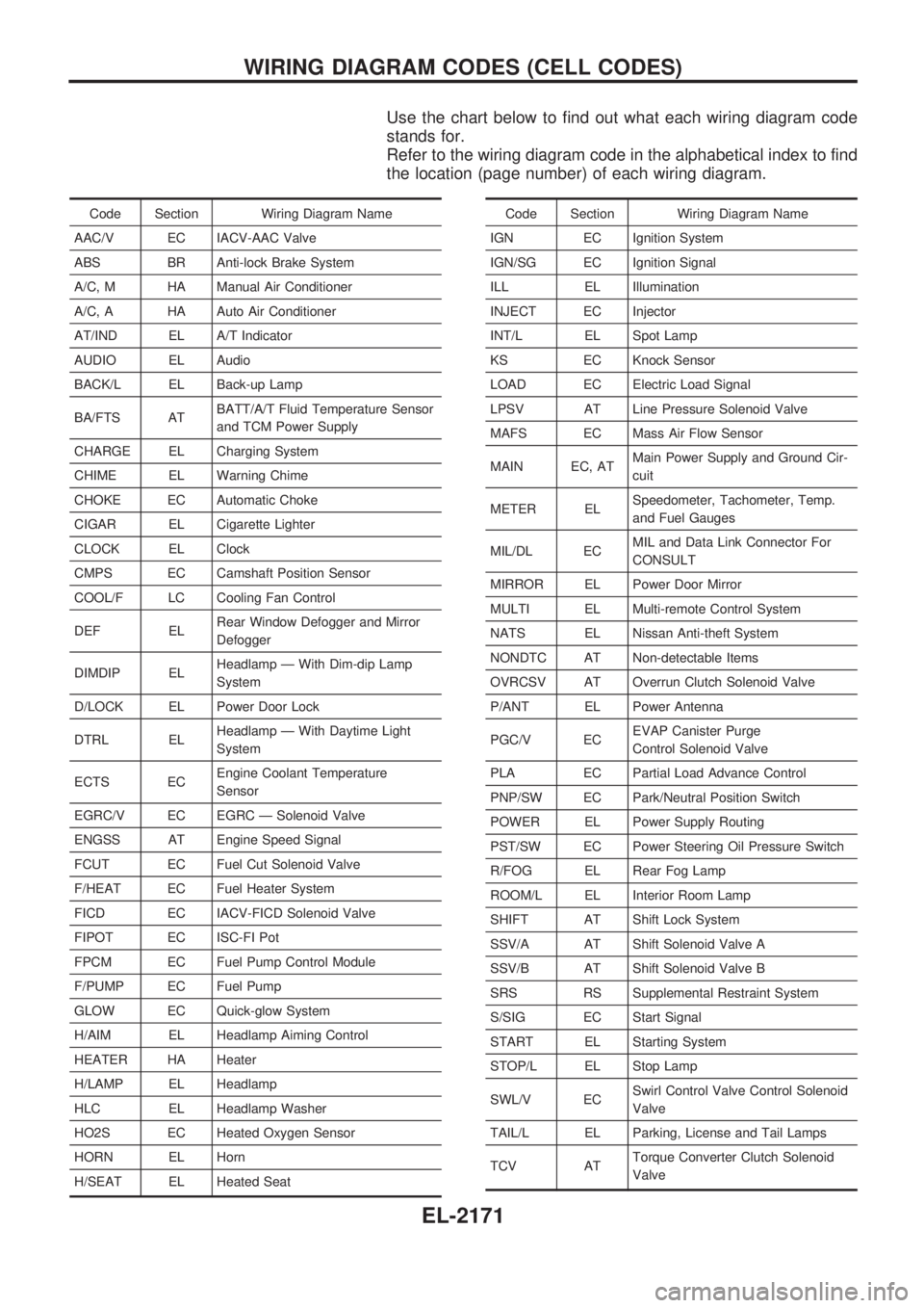
Use the chart below to find out what each wiring diagram code
stands for.
Refer to the wiring diagram code in the alphabetical index to find
the location (page number) of each wiring diagram.
Code Section Wiring Diagram Name
AAC/V EC IACV-AAC Valve
ABS BR Anti-lock Brake System
A/C, M HA Manual Air Conditioner
A/C, A HA Auto Air Conditioner
AT/IND EL A/T Indicator
AUDIO EL Audio
BACK/L EL Back-up Lamp
BA/FTS ATBATT/A/T Fluid Temperature Sensor
and TCM Power Supply
CHARGE EL Charging System
CHIME EL Warning Chime
CHOKE EC Automatic Choke
CIGAR EL Cigarette Lighter
CLOCK EL Clock
CMPS EC Camshaft Position Sensor
COOL/F LC Cooling Fan Control
DEF ELRear Window Defogger and Mirror
Defogger
DIMDIP ELHeadlamp Ð With Dim-dip Lamp
System
D/LOCK EL Power Door Lock
DTRL ELHeadlamp Ð With Daytime Light
System
ECTS ECEngine Coolant Temperature
Sensor
EGRC/V EC EGRC Ð Solenoid Valve
ENGSS AT Engine Speed Signal
FCUT EC Fuel Cut Solenoid Valve
F/HEAT EC Fuel Heater System
FICD EC IACV-FICD Solenoid Valve
FIPOT EC ISC-FI Pot
FPCM EC Fuel Pump Control Module
F/PUMP EC Fuel Pump
GLOW EC Quick-glow System
H/AIM EL Headlamp Aiming Control
HEATER HA Heater
H/LAMP EL Headlamp
HLC EL Headlamp Washer
HO2S EC Heated Oxygen Sensor
HORN EL Horn
H/SEAT EL Heated SeatCode Section Wiring Diagram Name
IGN EC Ignition System
IGN/SG EC Ignition Signal
ILL EL Illumination
INJECT EC Injector
INT/L EL Spot Lamp
KS EC Knock Sensor
LOAD EC Electric Load Signal
LPSV AT Line Pressure Solenoid Valve
MAFS EC Mass Air Flow Sensor
MAIN EC, ATMain Power Supply and Ground Cir-
cuit
METER ELSpeedometer, Tachometer, Temp.
and Fuel Gauges
MIL/DL ECMIL and Data Link Connector For
CONSULT
MIRROR EL Power Door Mirror
MULTI EL Multi-remote Control System
NATS EL Nissan Anti-theft System
NONDTC AT Non-detectable Items
OVRCSV AT Overrun Clutch Solenoid Valve
P/ANT EL Power Antenna
PGC/V ECEVAP Canister Purge
Control Solenoid Valve
PLA EC Partial Load Advance Control
PNP/SW EC Park/Neutral Position Switch
POWER EL Power Supply Routing
PST/SW EC Power Steering Oil Pressure Switch
R/FOG EL Rear Fog Lamp
ROOM/L EL Interior Room Lamp
SHIFT AT Shift Lock System
SSV/A AT Shift Solenoid Valve A
SSV/B AT Shift Solenoid Valve B
SRS RS Supplemental Restraint System
S/SIG EC Start Signal
START EL Starting System
STOP/L EL Stop Lamp
SWL/V ECSwirl Control Valve Control Solenoid
Valve
TAIL/L EL Parking, License and Tail Lamps
TCV ATTorque Converter Clutch Solenoid
Valve
WIRING DIAGRAM CODES (CELL CODES)
EL-2171