brake NISSAN PICK-UP 2001 Repair Manual
[x] Cancel search | Manufacturer: NISSAN, Model Year: 2001, Model line: PICK-UP, Model: NISSAN PICK-UP 2001Pages: 1306, PDF Size: 31.7 MB
Page 1 of 1306
GENERAL INFORMATIONGI
MAINTENANCEMA
ENGINE MECHANICALEM
ENGINE LUBRICATION &
COOLING SYSTEMSLC
ENGINE CONTROL SYSTEMEC
ACCELERATOR CONTROL, FUEL &
EXHAUST SYSTEMSFE
CLUTCHCL
MANUAL TRANSAXLEMT
TRANSFERTF
PROPELLER SHAFT &
DIFFERENTIAL CARRIERPD
FRONT AXLE & FRONT SUSPENSIONFA
REAR AXLE & REAR SUSPENSIONRA
BRAKE SYSTEMBR
STEERING SYSTEMST
RESTRAINT SYSTEMRS
BODY & TRIMBT
HEATER & AIR CONDITIONERHA
ELECTRICAL SYSTEMEL
ALPHABETICAL INDEXIDX
PICKUP
MODEL D22 SERIES
FOREWORD
This supplement contains informa-
tion concerning necessary service
procedures and relevant data for the
model D22 series.
All information, illustrations and spe-
ci®cations contained in this supple-
ment are based on the latest product
information available at the time of
publication. If your NISSAN model
differs from the speci®cations contain-
ed in this supplement, consult your
NISSAN distributor for information.
The right is reserved to make chan-
ges in speci®cations and methods at
any time without notice.
Edition: November 2001
Printing: November 2001 (01)
Publication No.: SM1E-D22CE0E
NISSAN EUROPE S.A.S.
2001 NISSAN EUROPE S.A.S. Printed in the Netherlands
Not to be reproduced in whole or in part without the prior written permission of Nissan Europe S.A.S., Paris, France.
QUICK REFERENCE INDEX
Page 11 of 1306
BRAKE SYSTEM
SECTION
BR
MODIFICATION NOTICE:
lWiring Diagrams have been changed.
CONTENTS
TROUBLE DIAGNOSES..................................... 3002
Schematic/3 Wheel Sensors Models ............... 3002
Wiring Diagram - ABS -/3 Wheel Sensors LHD
Models.............................................................. 3003
Wiring Diagram - ABS -/3 Wheel Sensors
RHD Models..................................................... 3006Schematic/4 Wheel Sensors Models ............... 3009
Wiring Diagram - ABS -/4 Wheel Sensors LHD
Models.............................................................. 3010
Wiring Diagram - ABS -/4 Wheel Sensors
RHD Models..................................................... 3013
BR
Page 460 of 1306
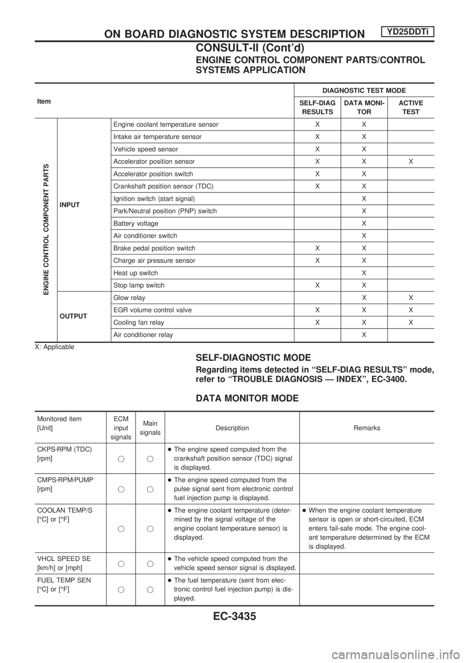
ENGINE CONTROL COMPONENT PARTS/CONTROL
SYSTEMS APPLICATION
ItemDIAGNOSTIC TEST MODE
SELF-DIAG
RESULTSDATA MONI-
TORACTIVE
TEST
ENGINE CONTROL COMPONENT PARTS
INPUTEngine coolant temperature sensor X X
Intake air temperature sensor X X
Vehicle speed sensor X X
Accelerator position sensor X X X
Accelerator position switch X X
Crankshaft position sensor (TDC) X X
Ignition switch (start signal) X
Park/Neutral position (PNP) switch X
Battery voltage X
Air conditioner switch X
Brake pedal position switch X X
Charge air pressure sensor X X
Heat up switch X
Stop lamp switch X X
OUTPUTGlow relayXX
EGR volume control valve X X X
Cooling fan relay X X X
Air conditioner relay X
X: Applicable
SELF-DIAGNOSTIC MODE
Regarding items detected in ªSELF-DIAG RESULTSº mode,
refer to ªTROUBLE DIAGNOSIS Ð INDEXº, EC-3400.
DATA MONITOR MODE
Monitored item
[Unit]ECM
input
signalsMain
signalsDescription Remarks
CKPSzRPM (TDC)
[rpm]jj+The engine speed computed from the
crankshaft position sensor (TDC) signal
is displayed.
CMPSzRPMzPUMP
[rpm]jj+The engine speed computed from the
pulse signal sent from electronic control
fuel injection pump is displayed.
COOLAN TEMP/S
[ÉC] or [ÉF]
jj+The engine coolant temperature (deter-
mined by the signal voltage of the
engine coolant temperature sensor) is
displayed.+When the engine coolant temperature
sensor is open or short-circuited, ECM
enters fail-safe mode. The engine cool-
ant temperature determined by the ECM
is displayed.
VHCL SPEED SE
[km/h] or [mph]jj+The vehicle speed computed from the
vehicle speed sensor signal is displayed.
FUEL TEMP SEN
[ÉC] or [ÉF]jj+The fuel temperature (sent from elec-
tronic control fuel injection pump) is dis-
played.
ON BOARD DIAGNOSTIC SYSTEM DESCRIPTIONYD25DDTi
CONSULT-II (Cont'd)
EC-3435
Page 461 of 1306
![NISSAN PICK-UP 2001 Repair Manual Monitored item
[Unit]ECM
input
signalsMain
signalsDescription Remarks
ACCEL POS SEN [V]
jj+The accelerator position sensor signal
voltage is displayed.
FULL ACCEL SW
[ON/OFF]jj+Indicates [ON/OFF] cond](/img/5/57372/w960_57372-460.png "NISSAN PICK-UP 2001 Repair Manual Monitored item
[Unit]ECM
input
signalsMain
signalsDescription Remarks
ACCEL POS SEN [V]
jj+The accelerator position sensor signal
voltage is displayed.
FULL ACCEL SW
[ON/OFF]jj+Indicates [ON/OFF] cond")
Monitored item
[Unit]ECM
input
signalsMain
signalsDescription Remarks
ACCEL POS SEN [V]
jj+The accelerator position sensor signal
voltage is displayed.
FULL ACCEL SW
[ON/OFF]jj+Indicates [ON/OFF] condition from the
accelerator position switch signal.
OFF ACCEL SW
[ON/OFF]jj+Indicates [ON/OFF] condition from the
accelerator position switch signal.
SPILL/V [ÉCA]
j+The control position of spill valve (sent
from electronic control fuel injection
pump) is displayed.
BATTERY VOLT [V]
jj+The power supply voltage of ECM is dis-
played.
I/C INT/A T/S [V]
jj+The signal voltage of the intake air tem-
perature sensor is displayed.
P/N POSI SW
[ON/OFF]jj+Indicates [ON/OFF] condition from the
park/neutral position switch signal.
START SIGNAL
[ON/OFF]jj+Indicates [ON/OFF] condition from the
starter signal.+After starting the engine, [OFF] is dis-
played regardless of the starter signal.
AIR COND SIG
[ON/OFF]jj+Indicates [ON/OFF] condition of the air
conditioner switch as determined by the
air conditioner signal.
BRAKE SW [ON/OFF]
jj+Indicates [ON/OFF] condition from the
stop lamp switch signal.
BRAKE SW2
[ON/OFF]jj+Indicates [ON/OFF] condition from the
brake pedal position switch.
IGN SW
[ON/OFF]jj+Indicates [ON/OFF] condition from igni-
tion switch signal.
WARM UP SW
[ON/OFF]j+Indicates [ON/OFF] condition from the
heat up switch signal.
TURBO BST SEN
[kPa]j+The charge air pressure (determined by
the signal voltage sent to the ECM) is
displayed.
DECELER F/CUT
[ON/OFF]j+The [ON/OFF] condition from decelera-
tion fuel cut signal (sent from ECM) is
displayed.
INJ TIMG C/V [%]
j+The duty ratio of fuel injection timing
control valve (sent from electronic con-
trol fuel injection pump) is displayed.
AIR COND RLY
[ON/OFF]j+Indicates the control condition of the air
conditioner relay (determined by ECM
according to the input signals).
GLOW RLY [ON/OFF]
j+The glow relay control condition (deter-
mined by ECM according to the input
signal) is displayed.
COOLING FAN
[ON/OFF]
j+Indicates the control condition of the
cooling fans (determined by ECM
according to the input signal).
+ON ... Operates.
OFF ... Stopped.
ON BOARD DIAGNOSTIC SYSTEM DESCRIPTIONYD25DDTi
CONSULT-II (Cont'd)
EC-3436
Page 485 of 1306
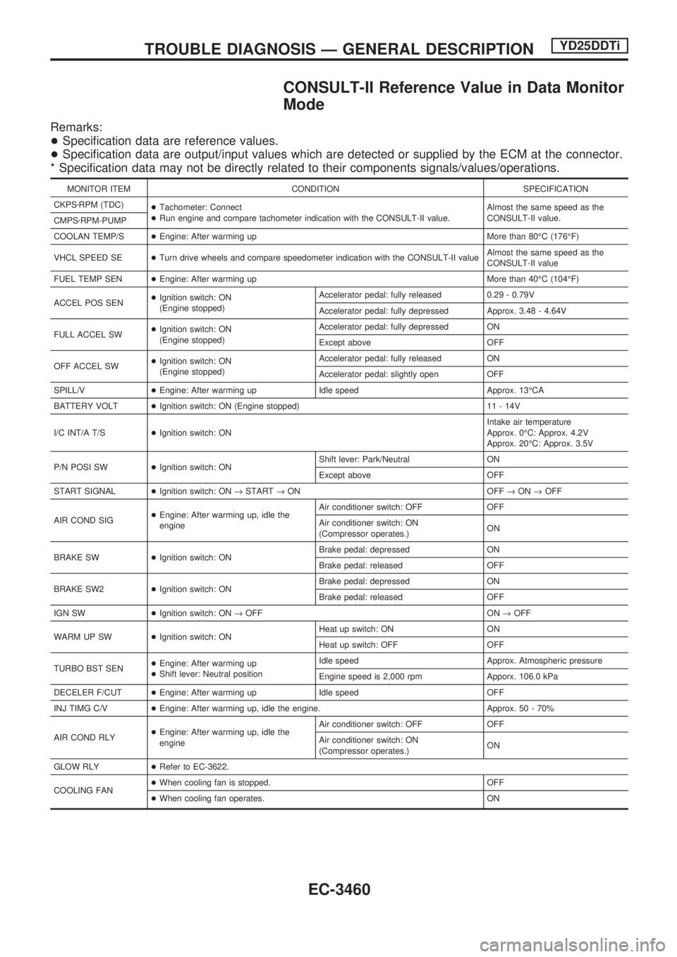
CONSULT-II Reference Value in Data Monitor
Mode
Remarks:
+Specification data are reference values.
+Specification data are output/input values which are detected or supplied by the ECM at the connector.
* Specification data may not be directly related to their components signals/values/operations.
MONITOR ITEM CONDITION SPECIFICATION
CKPSzRPM (TDC)
+Tachometer: Connect
+Run engine and compare tachometer indication with the CONSULT-II value.Almost the same speed as the
CONSULT-II value.
CMPSzRPM-PUMP
COOLAN TEMP/S+Engine: After warming up More than 80ÉC (176ÉF)
VHCL SPEED SE+Turn drive wheels and compare speedometer indication with the CONSULT-II valueAlmost the same speed as the
CONSULT-II value
FUEL TEMP SEN+Engine: After warming up More than 40ÉC (104ÉF)
ACCEL POS SEN+Ignition switch: ON
(Engine stopped)Accelerator pedal: fully released 0.29 - 0.79V
Accelerator pedal: fully depressed Approx. 3.48 - 4.64V
FULL ACCEL SW+Ignition switch: ON
(Engine stopped)Accelerator pedal: fully depressed ON
Except above OFF
OFF ACCEL SW+Ignition switch: ON
(Engine stopped)Accelerator pedal: fully released ON
Accelerator pedal: slightly open OFF
SPILL/V+Engine: After warming up Idle speed Approx. 13ÉCA
BATTERY VOLT+Ignition switch: ON (Engine stopped) 11 - 14V
I/C INT/A T/S+Ignition switch: ONIntake air temperature
Approx. 0ÉC: Approx. 4.2V
Approx. 20ÉC: Approx. 3.5V
P/N POSI SW+Ignition switch: ONShift lever: Park/Neutral ON
Except above OFF
START SIGNAL+Ignition switch: ON®START®ON OFF®ON®OFF
AIR COND SIG+Engine: After warming up, idle the
engineAir conditioner switch: OFF OFF
Air conditioner switch: ON
(Compressor operates.)ON
BRAKE SW+Ignition switch: ONBrake pedal: depressed ON
Brake pedal: released OFF
BRAKE SW2+Ignition switch: ONBrake pedal: depressed ON
Brake pedal: released OFF
IGN SW+Ignition switch: ON®OFF ON®OFF
WARM UP SW+Ignition switch: ONHeat up switch: ON ON
Heat up switch: OFF OFF
TURBO BST SEN+Engine: After warming up
+Shift lever: Neutral positionIdle speed Approx. Atmospheric pressure
Engine speed is 2,000 rpm Apporx. 106.0 kPa
DECELER F/CUT+Engine: After warming up Idle speed OFF
INJ TIMG C/V+Engine: After warming up, idle the engine. Approx. 50 - 70%
AIR COND RLY+Engine: After warming up, idle the
engineAir conditioner switch: OFF OFF
Air conditioner switch: ON
(Compressor operates.)ON
GLOW RLY+Refer to EC-3622.
COOLING FAN+When cooling fan is stopped. OFF
+When cooling fan operates. ON
TROUBLE DIAGNOSIS Ð GENERAL DESCRIPTIONYD25DDTi
EC-3460
Page 490 of 1306
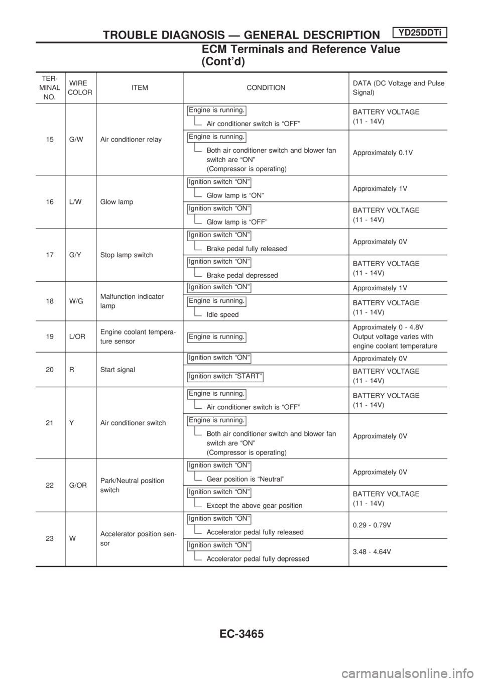
TER-
MINAL
NO.WIRE
COLORITEM CONDITIONDATA (DC Voltage and Pulse
Signal)
15 G/W Air conditioner relayEngine is running.
Air conditioner switch is ªOFFºBATTERY VOLTAGE
(11 - 14V)
Engine is running.
Both air conditioner switch and blower fan
switch are ªONº
(Compressor is operating)Approximately 0.1V
16 L/W Glow lampIgnition switch ªONº
Glow lamp is ªONºApproximately 1V
Ignition switch ªONº
Glow lamp is ªOFFºBATTERY VOLTAGE
(11 - 14V)
17 G/Y Stop lamp switchIgnition switch ªONº
Brake pedal fully releasedApproximately 0V
Ignition switch ªONº
Brake pedal depressedBATTERY VOLTAGE
(11 - 14V)
18 W/GMalfunction indicator
lampIgnition switch ªONº
Approximately 1V
Engine is running.
Idle speedBATTERY VOLTAGE
(11 - 14V)
19 L/OREngine coolant tempera-
ture sensorEngine is running.
Approximately 0 - 4.8V
Output voltage varies with
engine coolant temperature
20 R Start signalIgnition switch ªONº
Approximately 0V
Ignition switch ªSTARTº
BATTERY VOLTAGE
(11 - 14V)
21 Y Air conditioner switchEngine is running.
Air conditioner switch is ªOFFºBATTERY VOLTAGE
(11 - 14V)
Engine is running.
Both air conditioner switch and blower fan
switch are ªONº
(Compressor is operating)Approximately 0V
22 G/ORPark/Neutral position
switchIgnition switch ªONº
Gear position is ªNeutralºApproximately 0V
Ignition switch ªONº
Except the above gear positionBATTERY VOLTAGE
(11 - 14V)
23 WAccelerator position sen-
sorIgnition switch ªONº
Accelerator pedal fully released0.29 - 0.79V
Ignition switch ªONº
Accelerator pedal fully depressed3.48 - 4.64V
TROUBLE DIAGNOSIS Ð GENERAL DESCRIPTIONYD25DDTi
ECM Terminals and Reference Value
(Cont'd)
EC-3465
Page 491 of 1306
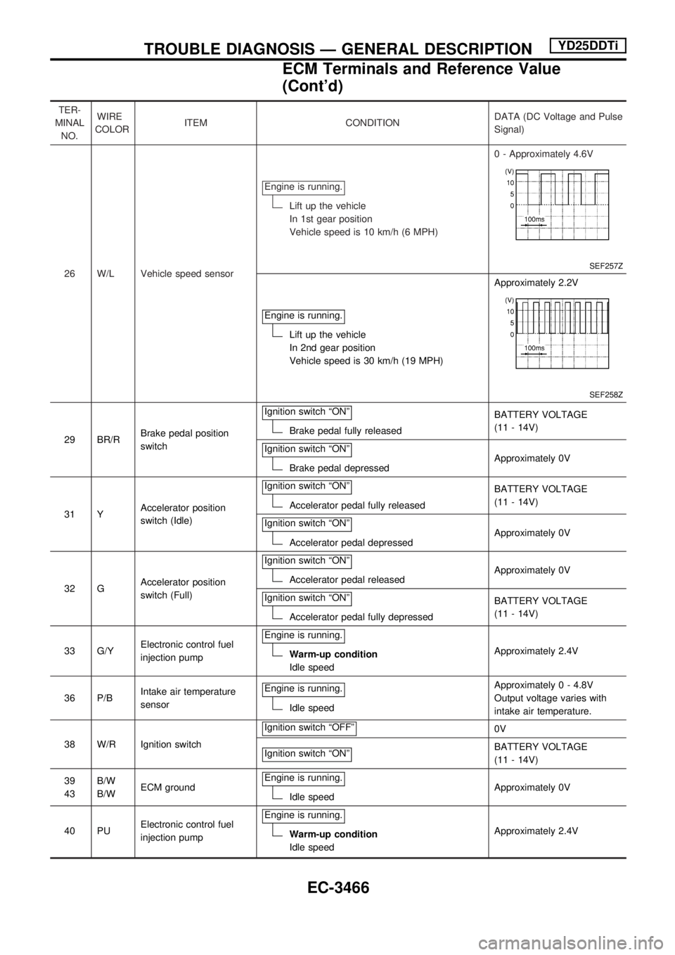
TER-
MINAL
NO.WIRE
COLORITEM CONDITIONDATA (DC Voltage and Pulse
Signal)
26 W/L Vehicle speed sensorEngine is running.
Lift up the vehicle
In 1st gear position
Vehicle speed is 10 km/h (6 MPH)0 - Approximately 4.6V
SEF257Z
Engine is running.
Lift up the vehicle
In 2nd gear position
Vehicle speed is 30 km/h (19 MPH)Approximately 2.2V
SEF258Z
29 BR/RBrake pedal position
switchIgnition switch ªONºBrake pedal fully releasedBATTERY VOLTAGE
(11 - 14V)
Ignition switch ªONº
Brake pedal depressedApproximately 0V
31 YAccelerator position
switch (Idle)Ignition switch ªONº
Accelerator pedal fully releasedBATTERY VOLTAGE
(11 - 14V)
Ignition switch ªONº
Accelerator pedal depressedApproximately 0V
32 GAccelerator position
switch (Full)Ignition switch ªONº
Accelerator pedal releasedApproximately 0V
Ignition switch ªONº
Accelerator pedal fully depressedBATTERY VOLTAGE
(11 - 14V)
33 G/YElectronic control fuel
injection pumpEngine is running.
Warm-up condition
Idle speedApproximately 2.4V
36 P/BIntake air temperature
sensorEngine is running.
Idle speedApproximately 0 - 4.8V
Output voltage varies with
intake air temperature.
38 W/R Ignition switchIgnition switch ªOFFº
0V
Ignition switch ªONº
BATTERY VOLTAGE
(11 - 14V)
39
43B/W
B/WECM groundEngine is running.
Idle speedApproximately 0V
40 PUElectronic control fuel
injection pumpEngine is running.
Warm-up condition
Idle speedApproximately 2.4V
TROUBLE DIAGNOSIS Ð GENERAL DESCRIPTIONYD25DDTi
ECM Terminals and Reference Value
(Cont'd)
EC-3466
Page 610 of 1306
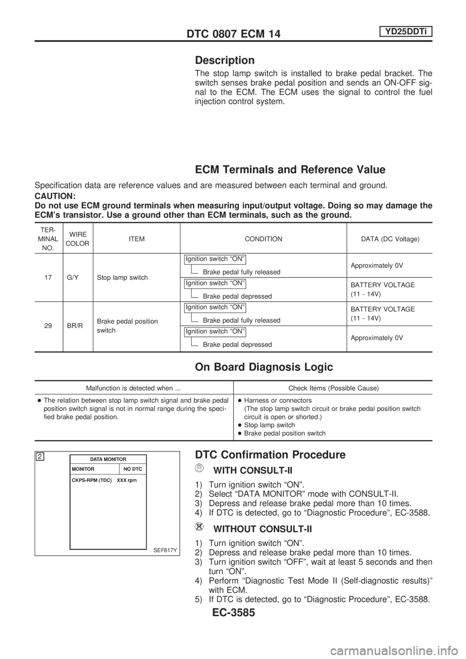
Description
The stop lamp switch is installed to brake pedal bracket. The
switch senses brake pedal position and sends an ON-OFF sig-
nal to the ECM. The ECM uses the signal to control the fuel
injection control system.
ECM Terminals and Reference Value
Specification data are reference values and are measured between each terminal and ground.
CAUTION:
Do not use ECM ground terminals when measuring input/output voltage. Doing so may damage the
ECM's transistor. Use a ground other than ECM terminals, such as the ground.
TER-
MINAL
NO.WIRE
COLORITEM CONDITION DATA (DC Voltage)
17 G/Y Stop lamp switchIgnition switch ªONº
Brake pedal fully releasedApproximately 0V
Ignition switch ªONº
Brake pedal depressedBATTERY VOLTAGE
(11 - 14V)
29 BR/RBrake pedal position
switchIgnition switch ªONº
Brake pedal fully releasedBATTERY VOLTAGE
(11 - 14V)
Ignition switch ªONº
Brake pedal depressedApproximately 0V
On Board Diagnosis Logic
Malfunction is detected when ... Check Items (Possible Cause)
+The relation between stop lamp switch signal and brake pedal
position switch signal is not in normal range during the speci-
fied brake pedal position.+Harness or connectors
(The stop lamp switch circuit or brake pedal position switch
circuit is open or shorted.)
+Stop lamp switch
+Brake pedal position switch
DTC Confirmation Procedure
WITH CONSULT-II
1) Turn ignition switch ªONº.
2) Select ªDATA MONITORº mode with CONSULT-II.
3) Depress and release brake pedal more than 10 times.
4) If DTC is detected, go to ªDiagnostic Procedureº, EC-3588.
WITHOUT CONSULT-II
1) Turn ignition switch ªONº.
2) Depress and release brake pedal more than 10 times.
3) Turn ignition switch ªOFFº, wait at least 5 seconds and then
turn ªONº.
4) Perform ªDiagnostic Test Mode II (Self-diagnostic results)º
with ECM.
5) If DTC is detected, go to ªDiagnostic Procedureº, EC-3588.SEF817Y
DTC 0807 ECM 14YD25DDTi
EC-3585
Page 612 of 1306
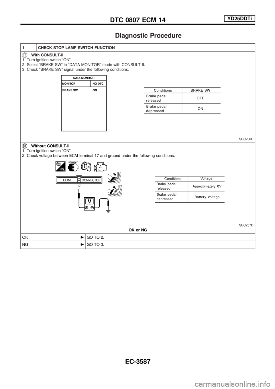
Diagnostic Procedure
1 CHECK STOP LAMP SWITCH FUNCTION
With CONSULT-II
1. Turn ignition switch ªONº.
2. Select ªBRAKE SWº in ªDATA MONITORº mode with CONSULT-II.
3. Check ªBRAKE SWº signal under the following conditions.
SEC256D
Without CONSULT-II
1. Turn ignition switch ªONº.
2. Check voltage between ECM terminal 17 and ground under the following conditions.
SEC257D
OK or NG
OKcGO TO 2.
NGcGO TO 3.
DTC 0807 ECM 14YD25DDTi
EC-3587
Page 613 of 1306
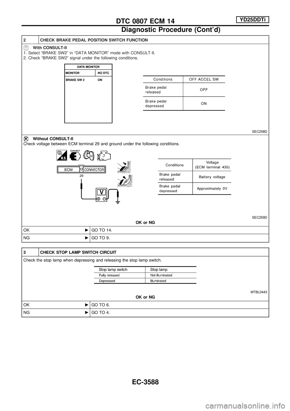
2 CHECK BRAKE PEDAL POSITION SWITCH FUNCTION
With CONSULT-II
1. Select ªBRAKE SW2º in ªDATA MONITORº mode with CONSULT-II.
2. Check ªBRAKE SW2º signal under the following conditions.
SEC258D
Without CONSULT-II
Check voltage between ECM terminal 29 and ground under the following conditions.
SEC259D
OK or NG
OKcGO TO 14.
NGcGO TO 9.
3 CHECK STOP LAMP SWITCH CIRCUIT
Check the stop lamp when depressing and releasing the stop lamp switch.
MTBL0443
OK or NG
OKcGO TO 6.
NGcGO TO 4.
DTC 0807 ECM 14YD25DDTi
Diagnostic Procedure (Cont'd)
EC-3588