air condition NISSAN PICK-UP 2003 Repair Manual
[x] Cancel search | Manufacturer: NISSAN, Model Year: 2003, Model line: PICK-UP, Model: NISSAN PICK-UP 2003Pages: 229, PDF Size: 8.89 MB
Page 1 of 229
GENERAL INFORMATIONGI
MAINTENANCEMA
ENGINE MECHANICALEM
ENGINE LUBRICATION &
COOLING SYSTEMSLC
ENGINE CONTROL SYSTEMEC
ACCELERATOR CONTROL, FUEL &
EXHAUST SYSTEMSFE
CLUTCHCL
MANUAL TRANSAXLEMT
TRANSFERTF
PROPELLER SHAFT &
DIFFERENTIAL CARRIERPD
FRONT AXLE & FRONT SUSPENSIONFA
REAR AXLE & REAR SUSPENSIONRA
BRAKE SYSTEMBR
STEERING SYSTEMST
RESTRAINT SYSTEMRS
BODY & TRIMBT
HEATER & AIR CONDITIONERHA
ELECTRICAL SYSTEMEL
ALPHABETICAL INDEXIDX
PICKUP
MODEL D22 SERIES
FOREWORD
This supplement contains informa-
tion concerning necessary service
procedures and relevant data for the
model D22 series.
All information, illustrations and spe-
ci®cations contained in this supple-
ment are based on the latest product
information available at the time of
publication. If your NISSAN model
differs from the speci®cations contain-
ed in this supplement, consult your
NISSAN distributor for information.
The right is reserved to make chan-
ges in speci®cations and methods at
any time without notice.
Edition: March 2003
Printing: April 2003 (01)
Publication No.: SM3E-D22DE0E
Reference No.: 7711346915
NISSAN EUROPE S.A.S.
2003 NISSAN EUROPE S.A.S. Printed in the Netherlands
Not to be reproduced in whole or in part without the prior written permission of Nissan Europe S.A.S., Paris, France.
QUICK REFERENCE INDEX
Page 5 of 229
ENGINE CONTROL SYSTEM
SECTION
EC
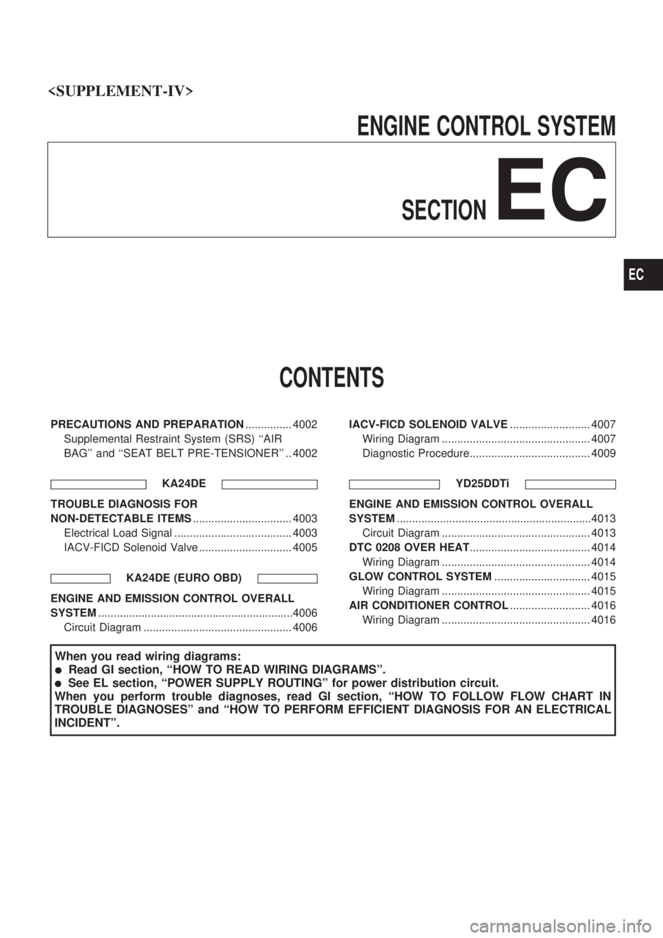
CONTENTS
PRECAUTIONS AND PREPARATION............... 4002
Supplemental Restraint System (SRS) ``AIR
BAG'' and ``SEAT BELT PRE-TENSIONER'' .. 4002
KA24DE
TROUBLE DIAGNOSIS FOR
NON-DETECTABLE ITEMS................................ 4003
Electrical Load Signal ...................................... 4003
IACV-FICD Solenoid Valve .............................. 4005
KA24DE (EURO OBD)
ENGINE AND EMISSION CONTROL OVERALL
SYSTEM...............................................................4006
Circuit Diagram ................................................ 4006IACV-FICD SOLENOID VALVE.......................... 4007
Wiring Diagram ................................................ 4007
Diagnostic Procedure....................................... 4009
YD25DDTi
ENGINE AND EMISSION CONTROL OVERALL
SYSTEM...............................................................4013
Circuit Diagram ................................................ 4013
DTC 0208 OVER HEAT....................................... 4014
Wiring Diagram ................................................ 4014
GLOW CONTROL SYSTEM............................... 4015
Wiring Diagram ................................................ 4015
AIR CONDITIONER CONTROL.......................... 4016
Wiring Diagram ................................................ 4016
When you read wiring diagrams:
lRead GI section, ªHOW TO READ WIRING DIAGRAMSº.
lSee EL section, ªPOWER SUPPLY ROUTINGº for power distribution circuit.
When you perform trouble diagnoses, read GI section, ªHOW TO FOLLOW FLOW CHART IN
TROUBLE DIAGNOSESº and ªHOW TO PERFORM EFFICIENT DIAGNOSIS FOR AN ELECTRICAL
INCIDENTº.
EC
Page 11 of 229

Wiring Diagram
MODEL WITH MANUAL AIR CONDITIONER
GEC389A
IACV-FICD SOLENOID VALVEKA24DE (EURO OBD)
EC-4007
Page 12 of 229

MODEL WITH AUTO AIR CONDITIONER
GEC390A
IACV-FICD SOLENOID VALVEKA24DE (EURO OBD)
Wiring Diagram (Cont'd)
EC-4008
Page 13 of 229
Diagnostic Procedure
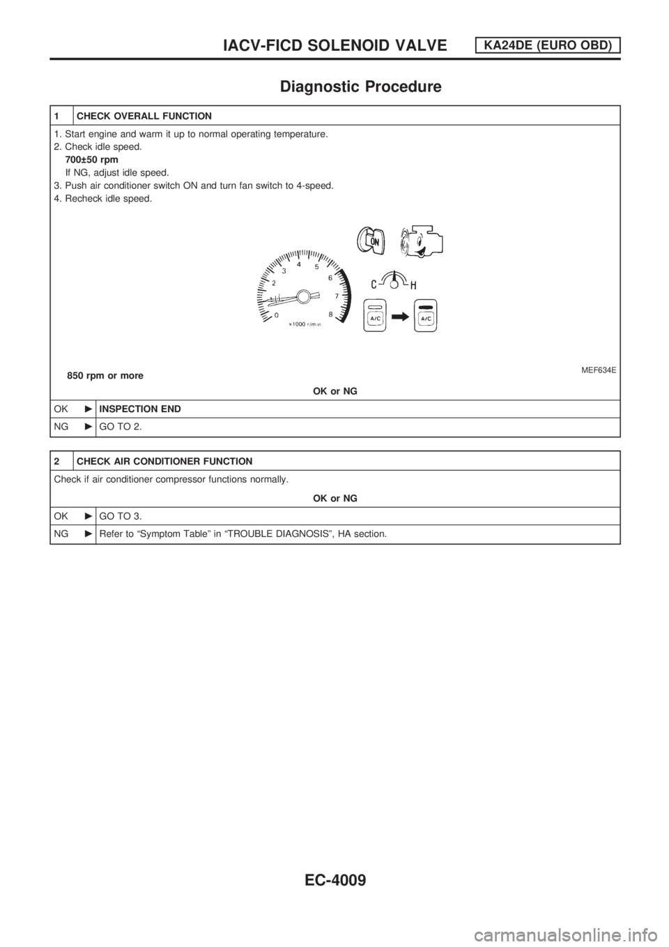
1 CHECK OVERALL FUNCTION
1. Start engine and warm it up to normal operating temperature.
2. Check idle speed.
700 50 rpm
If NG, adjust idle speed.
3. Push air conditioner switch ON and turn fan switch to 4-speed.
4. Recheck idle speed.
MEF634E850 rpm or more
OK or NG
OKcINSPECTION END
NGcGO TO 2.
2 CHECK AIR CONDITIONER FUNCTION
Check if air conditioner compressor functions normally.
OK or NG
OKcGO TO 3.
NGcRefer to ªSymptom Tableº in ªTROUBLE DIAGNOSISº, HA section.
IACV-FICD SOLENOID VALVEKA24DE (EURO OBD)
EC-4009
Page 14 of 229
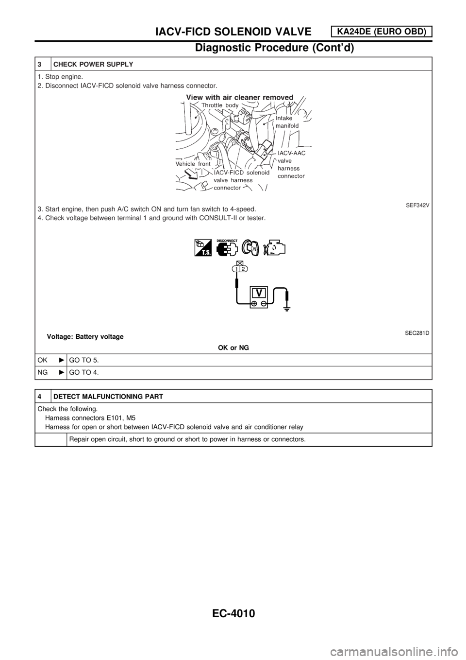
3 CHECK POWER SUPPLY
1. Stop engine.
2. Disconnect IACV-FICD solenoid valve harness connector.
SEF342V3. Start engine, then push A/C switch ON and turn fan switch to 4-speed.
4. Check voltage between terminal 1 and ground with CONSULT-II or tester.
SEC281DVoltage: Battery voltage
OK or NG
OKcGO TO 5.
NGcGO TO 4.
4 DETECT MALFUNCTIONING PART
Check the following.
Harness connectors E101, M5
Harness for open or short between IACV-FICD solenoid valve and air conditioner relay
Repair open circuit, short to ground or short to power in harness or connectors.
IACV-FICD SOLENOID VALVEKA24DE (EURO OBD)
Diagnostic Procedure (Cont'd)
EC-4010
Page 15 of 229

5 CHECK GROUND CIRCUIT
1. Turn ignition switch OFF.
2. Check harness continuity as follows.
MTBL1755
Continuity should exist.
3. Also check harness for short to ground or short to power.
OK or NG
OKcGO TO 7.
NGcGO TO 6.
6 DETECT MALFUNCTIONING PART
MANUAL AIR CONDITIONER
Check the following.
IACV-FICD solenoid valve
Ambient temperature switch
Diode M53
Harness connectors M5, E101
Check the harness for open or short between air conditioner relay and ambient temperature switch
Check the harness for open or short between diode M53 and ECM
Check the harness for open or short between ambient temperature switch and ECM
Check the harness for open or short between ambient temperature switch and ground
AUTO AIR CONDITIONER
Check the following.
Harness connectors E101, M5
IACV-FICD solenoid valve
Diode M83
Check the harness for open or short between air conditioner relay and ECM
Check the harness for open or short between diode M83 and A/C auto amp
Check the harness for open or short between A/C auto amp and ECM
cRepair open circuit or short to power in harness or connectors.
IACV-FICD SOLENOID VALVEKA24DE (EURO OBD)
Diagnostic Procedure (Cont'd)
EC-4011
Page 20 of 229

Wiring Diagram
GEC383A
AIR CONDITIONER CONTROLYD25DDTi
EC-4016
Page 21 of 229

GEC384A
AIR CONDITIONER CONTROLYD25DDTi
Wiring Diagram (Cont'd)
EC-4017
Page 103 of 229
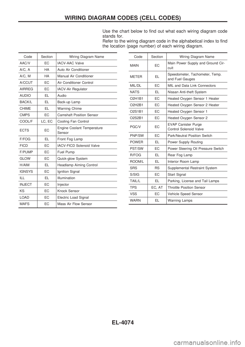
Use the chart below to find out what each wiring diagram code
stands for.
Refer to the wiring diagram code in the alphabetical index to find
the location (page number) of each wiring diagram.
Code Section Wiring Diagram Name
AAC/V EC IACV-AAC Valve
A/C, A HA Auto Air Conditioner
A/C, M HA Manual Air Conditioner
A/CCUT EC Air Conditioner Control
AIRREG EC IACV-Air Regulator
AUDIO EL Audio
BACK/L EL Back-up Lamp
CHIME EL Warning Chime
CMPS EC Camshaft Position Sensor
COOL/F LC, EC Cooling Fan Control
ECTS ECEngine Coolant Temperature
Sensor
F/FOG EL Front Fog Lamp
FICD EC IACV-FICD Solenoid Valve
F/PUMP EC Fuel Pump
GLOW EC Quick-glow System
H/AIM EL Headlamp Aiming Control
IGNSYS EC Ignition Signal
ILL EL Illumination
INJECT EC Injector
KS EC Knock Sensor
LOAD EC Electric Load Signal
MAFS EC Mass Air Flow SensorCode Section Wiring Diagram Name
MAIN ECMain Power Supply and Ground Cir-
cuit
METER ELSpeedometer, Tachometer, Temp.
and Fuel Gauges
MIL/DL EC MIL and Data Link Connectors
NATS EL Nissan Anti-theft System
O2H1B1 EC Heated Oxygen Sensor 1 Heater
O2H2B1 EC Heated Oxygen Sensor 2 Heater
O2S1B1 EC Heated Oxygen Sensor 1
O2S2B1 EC Heated Oxygen Sensor 2
PGC/V ECEVAP Canister Purge
Control Solenoid Valve
PNP/SW EC Park/Neutral Position Switch
POWER EL Power Supply Routing
PST/SW EC Power Steering Oil Pressure Switch
R/FOG EL Rear Fog Lamp
ROOM/L EL Interior Room Lamp
SRS RS Supplemental Restraint System
S/SIG EC Start Signal
TAIL/L EL Parking, License and Tail Lamps
TPS EC, AT Throttle Position Sensor
VSS EC Vehicle Speed Sensor
WARN EL Warning Lamps
WIRING DIAGRAM CODES (CELL CODES)
EL-4074