brake sensor NISSAN PRIMERA 1999 Electronic User Guide
[x] Cancel search | Manufacturer: NISSAN, Model Year: 1999, Model line: PRIMERA, Model: NISSAN PRIMERA 1999Pages: 2267, PDF Size: 35.74 MB
Page 182 of 2267
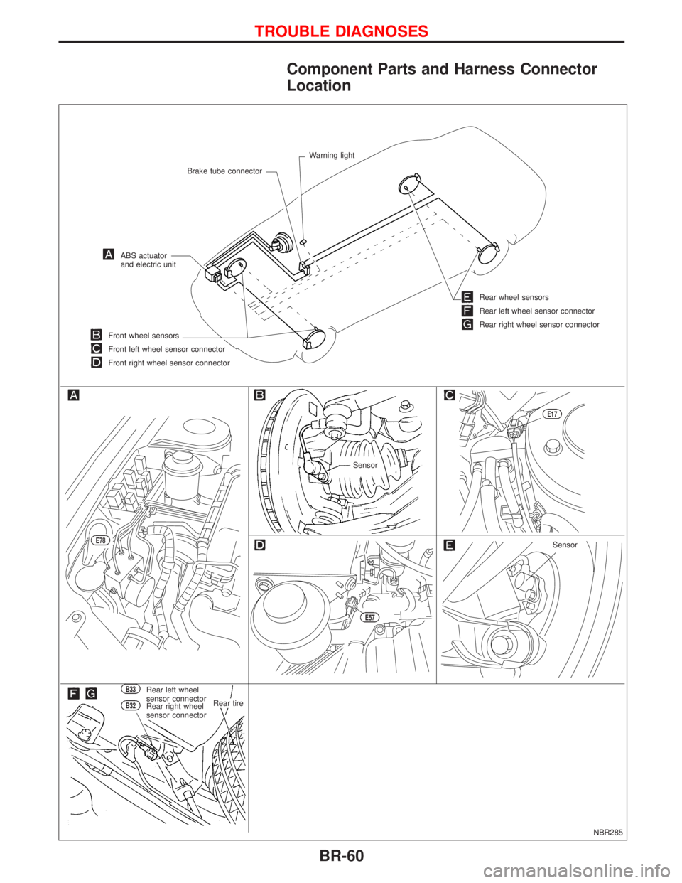
Component Parts and Harness Connector
Location
NBR285
Brake tube connectorWarning light
ABS actuator
and electric unit
Front wheel sensors
Front left wheel sensor connector
Front right wheel sensor connector
Sensor
E17
Rear wheel sensors
Rear left wheel sensor connector
Rear right wheel sensor connector
B33Rear left wheel
sensor connector
B32Rear right wheel
sensor connector.Rear tire
.E78
E57
Sensor
TROUBLE DIAGNOSES
BR-60
Page 195 of 2267
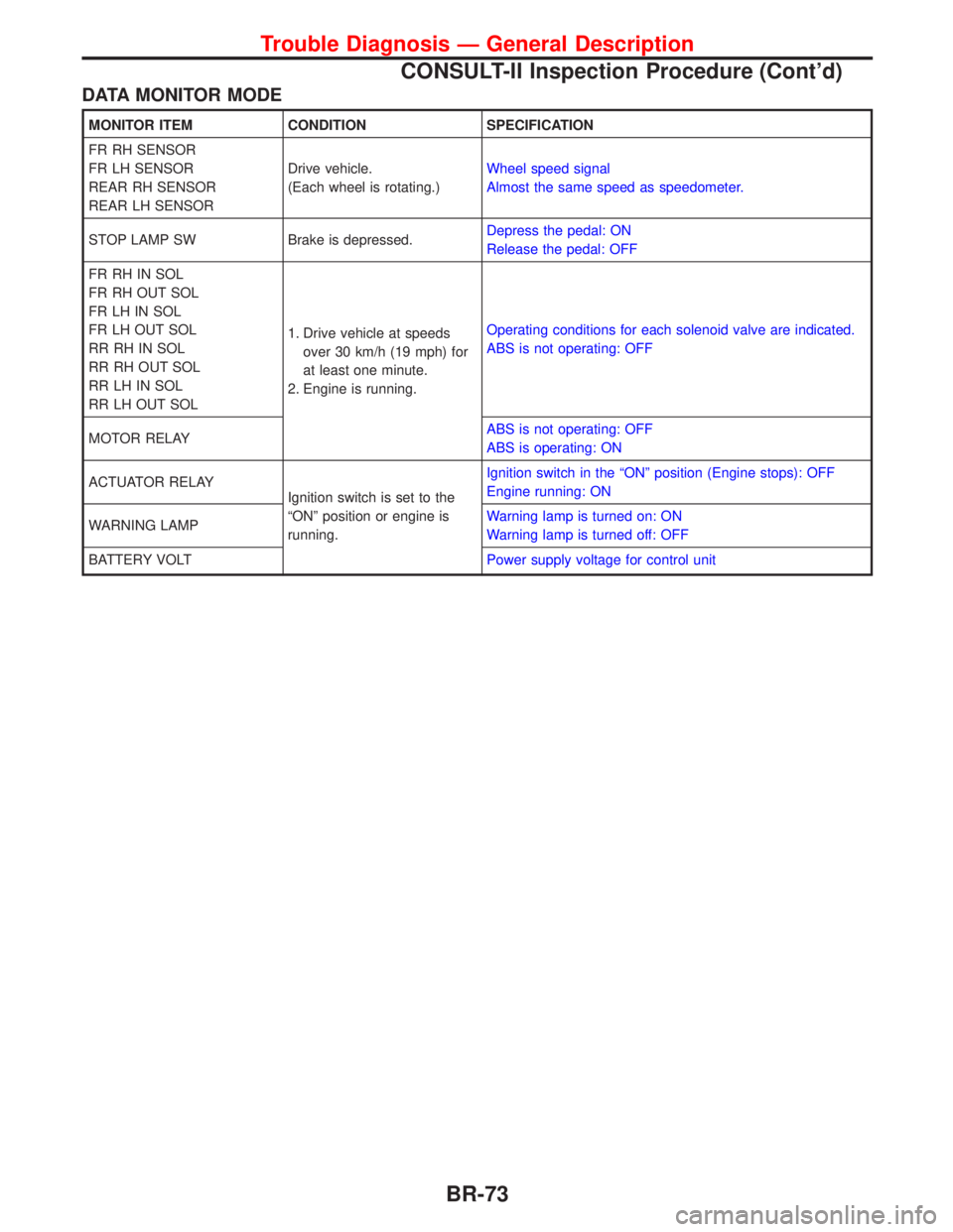
DATA MONITOR MODE
MONITOR ITEM CONDITION SPECIFICATION
FR RH SENSOR
FR LH SENSOR
REAR RH SENSOR
REAR LH SENSORDrive vehicle.
(Each wheel is rotating.)Wheel speed signal
Almost the same speed as speedometer.
STOP LAMP SW Brake is depressed.Depress the pedal: ON
Release the pedal: OFF
FR RH IN SOL
FR RH OUT SOL
FR LH IN SOL
FR LH OUT SOL
RR RH IN SOL
RR RH OUT SOL
RR LH IN SOL
RR LH OUT SOL1. Drive vehicle at speeds
over 30 km/h (19 mph) for
at least one minute.
2. Engine is running.Operating conditions for each solenoid valve are indicated.
ABS is not operating: OFF
MOTOR RELAYABS is not operating: OFF
ABS is operating: ON
ACTUATOR RELAY
Ignition switch is set to the
ªONº position or engine is
running.Ignition switch in the ªONº position (Engine stops): OFF
Engine running: ON
WARNING LAMPWarning lamp is turned on: ON
Warning lamp is turned off: OFF
BATTERY VOLTPower supply voltage for control unit
Trouble Diagnosis Ð General Description
CONSULT-II Inspection Procedure (Cont'd)
BR-73
Page 198 of 2267
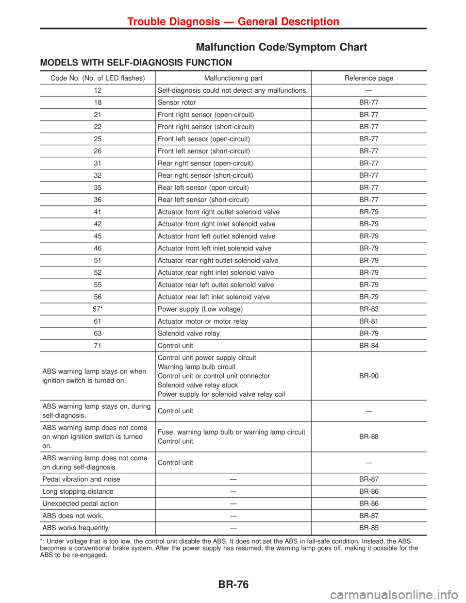
Malfunction Code/Symptom Chart
MODELS WITH SELF-DIAGNOSIS FUNCTION
Code No. (No. of LED flashes) Malfunctioning part Reference page
12 Self-diagnosis could not detect any malfunctions. Ð
18 Sensor rotor BR-77
21 Front right sensor (open-circuit) BR-77
22 Front right sensor (short-circuit) BR-77
25 Front left sensor (open-circuit) BR-77
26 Front left sensor (short-circuit) BR-77
31 Rear right sensor (open-circuit) BR-77
32 Rear right sensor (short-circuit) BR-77
35 Rear left sensor (open-circuit) BR-77
36 Rear left sensor (short-circuit) BR-77
41 Actuator front right outlet solenoid valve BR-79
42 Actuator front right inlet solenoid valve BR-79
45 Actuator front left outlet solenoid valve BR-79
46 Actuator front left inlet solenoid valve BR-79
51 Actuator rear right outlet solenoid valve BR-79
52 Actuator rear right inlet solenoid valve BR-79
55 Actuator rear left outlet solenoid valve BR-79
56 Actuator rear left inlet solenoid valve BR-79
57* Power supply (Low voltage) BR-83
61 Actuator motor or motor relay BR-81
63 Solenoid valve relay BR-79
71 Control unit BR-84
ABS warning lamp stays on when
ignition switch is turned on.Control unit power supply circuit
Warning lamp bulb circuit
Control unit or control unit connector
Solenoid valve relay stuck
Power supply for solenoid valve relay coilBR-90
ABS warning lamp stays on, during
self-diagnosis.Control unit Ð
ABS warning lamp does not come
on when ignition switch is turned
on.Fuse, warning lamp bulb or warning lamp circuit
Control unitBR-88
ABS warning lamp does not come
on during self-diagnosis.Control unit Ð
Pedal vibration and noise Ð BR-87
Long stopping distance Ð BR-86
Unexpected pedal action Ð BR-86
ABS does not work. Ð BR-87
ABS works frequently. Ð BR-85
*: Under voltage that is too low, the control unit disable the ABS. It does not set the ABS in fail-safe condition. Instead, the ABS
becomes a conventional brake system. After the power supply has resumed, the warning lamp goes off, making it possible for the
ABS to be re-engaged.
Trouble Diagnosis Ð General Description
BR-76
Page 208 of 2267
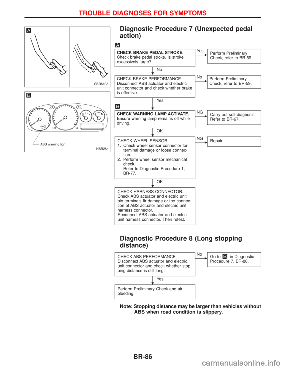
Diagnostic Procedure 7 (Unexpected pedal
action)
CHECK BRAKE PEDAL STROKE.
Check brake pedal stroke. Is stroke
excessively large?
No
EYe s
Perform Preliminary
Check, refer to BR-59.
CHECK BRAKE PERFORMANCE
Disconnect ABS actuator and electric
unit connector and check whether brake
is effective.
Ye s
ENo
Perform Preliminary
Check, refer to BR-59.
CHECK WARNING LAMP ACTIVATE.
Ensure warning lamp remains off while
driving.
OK
ENG
Carry out self-diagnosis.
Refer to BR-67.
CHECK WHEEL SENSOR.
1. Check wheel sensor connector for
terminal damage or loose connec-
tion.
2. Perform wheel sensor mechanical
check.
Refer to Diagnostic Procedure 1,
BR-77.
OK
ENG
Repair.
CHECK HARNESS CONNECTOR.
Check ABS actuator and electric unit
pin terminals fir damage or the connec-
tion of ABS actuator and electric unit
harness connector.
Reconnect ABS actuator and electric
unit harness connector. Then retest.
Diagnostic Procedure 8 (Long stopping
distance)
CHECK ABS PERFORMANCE
Disconnect ABS actuator and electric
unit connector and check whether stop-
ping distance is still long.
Ye s
ENo
Go toin Diagnostic
Procedure 7, BR-86.
Perform Preliminary Check and air
bleeding.
Note: Stopping distance may be larger than vehicles without
ABS when road condition is slippery.
SBR540A
NBR284 ABS warning light
H
H
H
H
H
TROUBLE DIAGNOSES FOR SYMPTOMS
BR-86
Page 209 of 2267
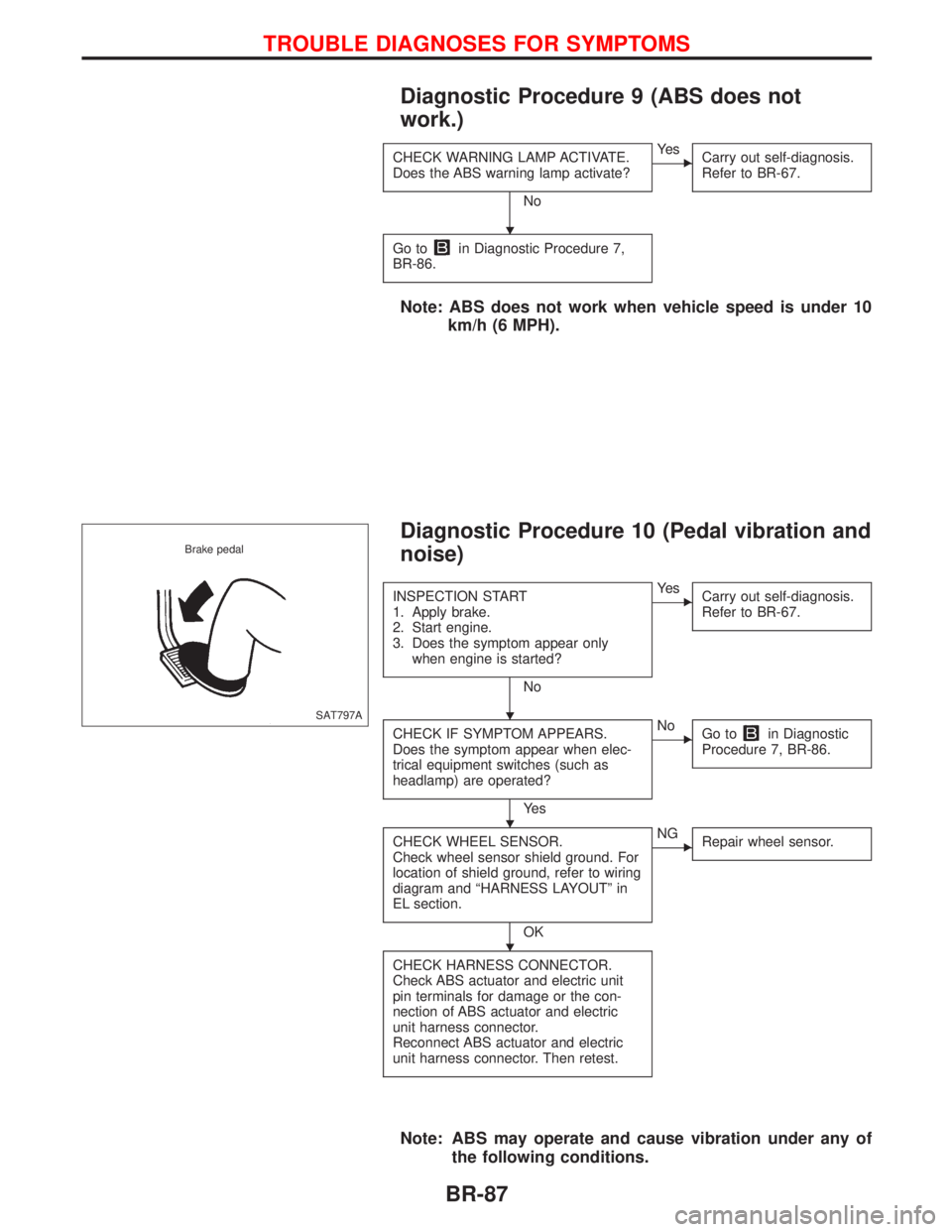
Diagnostic Procedure 9 (ABS does not
work.)
CHECK WARNING LAMP ACTIVATE.
Does the ABS warning lamp activate?
No
EYe s
Carry out self-diagnosis.
Refer to BR-67.
Go toin Diagnostic Procedure 7,
BR-86.
Note: ABS does not work when vehicle speed is under 10
km/h (6 MPH).
Diagnostic Procedure 10 (Pedal vibration and
noise)
INSPECTION START
1. Apply brake.
2. Start engine.
3. Does the symptom appear only
when engine is started?
No
EYe s
Carry out self-diagnosis.
Refer to BR-67.
CHECK IF SYMPTOM APPEARS.
Does the symptom appear when elec-
trical equipment switches (such as
headlamp) are operated?
Ye s
ENo
Go toin Diagnostic
Procedure 7, BR-86.
CHECK WHEEL SENSOR.
Check wheel sensor shield ground. For
location of shield ground, refer to wiring
diagram and ªHARNESS LAYOUTº in
EL section.
OK
ENG
Repair wheel sensor.
CHECK HARNESS CONNECTOR.
Check ABS actuator and electric unit
pin terminals for damage or the con-
nection of ABS actuator and electric
unit harness connector.
Reconnect ABS actuator and electric
unit harness connector. Then retest.
Note: ABS may operate and cause vibration under any of
the following conditions.
SAT797A Brake pedal
H
H
H
H
TROUBLE DIAGNOSES FOR SYMPTOMS
BR-87
Page 296 of 2267
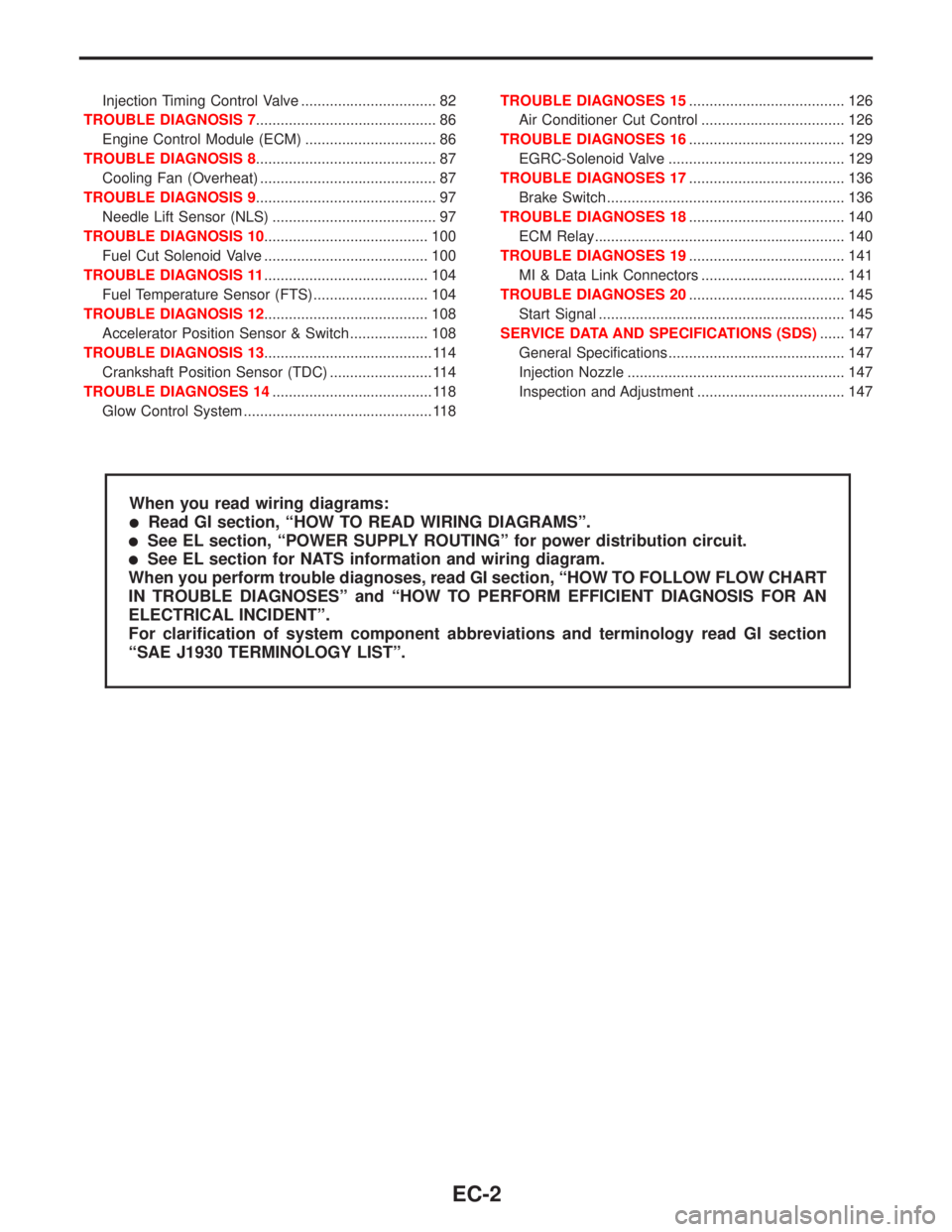
Injection Timing Control Valve ................................. 82
TROUBLE DIAGNOSIS 7............................................ 86
Engine Control Module (ECM) ................................ 86
TROUBLE DIAGNOSIS 8............................................ 87
Cooling Fan (Overheat) ........................................... 87
TROUBLE DIAGNOSIS 9............................................ 97
Needle Lift Sensor (NLS) ........................................ 97
TROUBLE DIAGNOSIS 10........................................ 100
Fuel Cut Solenoid Valve ........................................ 100
TROUBLE DIAGNOSIS 11........................................ 104
Fuel Temperature Sensor (FTS)............................ 104
TROUBLE DIAGNOSIS 12........................................ 108
Accelerator Position Sensor & Switch ................... 108
TROUBLE DIAGNOSIS 13......................................... 114
Crankshaft Position Sensor (TDC) ......................... 114
TROUBLE DIAGNOSES 14....................................... 118
Glow Control System .............................................. 118TROUBLE DIAGNOSES 15...................................... 126
Air Conditioner Cut Control ................................... 126
TROUBLE DIAGNOSES 16...................................... 129
EGRC-Solenoid Valve ........................................... 129
TROUBLE DIAGNOSES 17...................................... 136
Brake Switch .......................................................... 136
TROUBLE DIAGNOSES 18...................................... 140
ECM Relay............................................................. 140
TROUBLE DIAGNOSES 19...................................... 141
MI & Data Link Connectors ................................... 141
TROUBLE DIAGNOSES 20...................................... 145
Start Signal ............................................................ 145
SERVICE DATA AND SPECIFICATIONS (SDS)...... 147
General Specifications ........................................... 147
Injection Nozzle ..................................................... 147
Inspection and Adjustment .................................... 147
When you read wiring diagrams:
lRead GI section, ªHOW TO READ WIRING DIAGRAMSº.
lSee EL section, ªPOWER SUPPLY ROUTINGº for power distribution circuit.
lSee EL section for NATS information and wiring diagram.
When you perform trouble diagnoses, read GI section, ªHOW TO FOLLOW FLOW CHART
IN TROUBLE DIAGNOSESº and ªHOW TO PERFORM EFFICIENT DIAGNOSIS FOR AN
ELECTRICAL INCIDENTº.
For clarification of system component abbreviations and terminology read GI section
ªSAE J1930 TERMINOLOGY LISTº.
EC-2
Page 308 of 2267
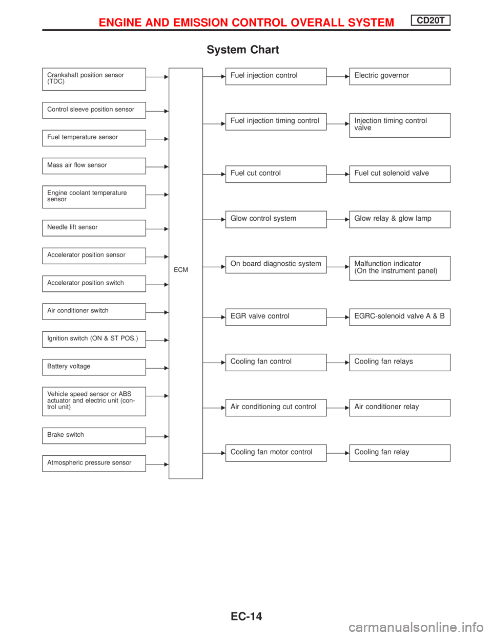
System Chart
Crankshaft position sensor
(TDC)E
ECM
Control sleeve position sensorE
Fuel temperature sensorE
Mass air flow sensorE
Engine coolant temperature
sensorE
Needle lift sensorE
Accelerator position sensorE
Accelerator position switchE
Air conditioner switchE
Ignition switch (ON & ST POS.)E
Battery voltageE
Vehicle speed sensor or ABS
actuator and electric unit (con-
trol unit)E
Brake switchE
Atmospheric pressure sensorE
EFuel injection controlEElectric governor
EFuel injection timing controlEInjection timing control
valve
EFuel cut controlEFuel cut solenoid valve
EGlow control systemEGlow relay & glow lamp
EOn board diagnostic systemEMalfunction indicator
(On the instrument panel)
EEGR valve controlEEGRC-solenoid valve A & B
ECooling fan controlECooling fan relays
EAir conditioning cut controlEAir conditioner relay
ECooling fan motor controlECooling fan relay
ENGINE AND EMISSION CONTROL OVERALL SYSTEMCD20T
EC-14
Page 322 of 2267
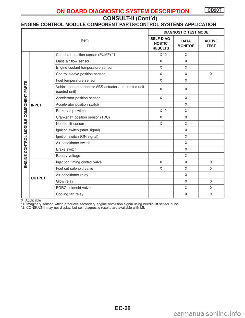
ENGINE CONTROL MODULE COMPONENT PARTS/CONTROL SYSTEMS APPLICATION
ItemDIAGNOSTIC TEST MODE
SELF-DIAG-
NOSTIC
RESULTSD ATA
MONITORACTIVE
TEST
ENGINE CONTROL MODULE COMPONENT PARTS
INPUTCamshaft position sensor (PUMP) *1 X *2 X
Mass air flow sensor X X
Engine coolant temperature sensor X X
Control sleeve position sensor X X X
Fuel temperature sensor X X
Vehicle speed sensor or ABS actuator and electric unit
(control unit)XX
Accelerator position sensor X X
Accelerator position switch X
Brake lamp switch X *2 X
Crankshaft position sensor (TDC) X X
Needle lift sensor X X
Ignition switch (start signal) X
Ignition switch (ON signal) X
Air conditioner switch X
Brake switch X
Battery voltage X
OUTPUTInjection timing control valve X X X
Fuel cut solenoid valve X X X
Air conditioner relay X
Glow relay X X
EGRC-solenoid valve X X
Cooling fan relay X X
X: Applicable
*1: Imaginary sensor, which produces secondary engine revolution signal using needle lift sensor pulse.
*2: CONSULT-II may not display, but self-diagnostic results are available with MI.
ON BOARD DIAGNOSTIC SYSTEM DESCRIPTIONCD20T
CONSULT-II (Cont'd)
EC-28
Page 323 of 2267
![NISSAN PRIMERA 1999 Electronic User Guide SELF-DIAGNOSTIC MODE
Regarding items detected in ªSELF-DIAG RESULTSº mode, refer to ªDiagnostic Trouble chartº.
DATA MONITOR MODE
Monitored item
[Unit]ECM
input
signalsMain
signalsDescription Rema](/img/5/57377/w960_57377-322.png "NISSAN PRIMERA 1999 Electronic User Guide SELF-DIAGNOSTIC MODE
Regarding items detected in ªSELF-DIAG RESULTSº mode, refer to ªDiagnostic Trouble chartº.
DATA MONITOR MODE
Monitored item
[Unit]ECM
input
signalsMain
signalsDescription Rema")
SELF-DIAGNOSTIC MODE
Regarding items detected in ªSELF-DIAG RESULTSº mode, refer to ªDiagnostic Trouble chartº.
DATA MONITOR MODE
Monitored item
[Unit]ECM
input
signalsMain
signalsDescription Remarks
CKPS×RPM
(TDC) [rpm]
qq
lThe engine speed computed from the
crankshaft position sensor (TDC) sig-
nal is displayed.
CMPS×RPM -
PUMP [rpm]
qq
lThe engine speed computed from the
camshaft position sensor (PUMP) sig-
nal is displayed.
COOLAN TEMP/S
[ÉC] or [ÉF]
qq
lThe engine coolant temperature (deter-
mined by the signal voltage of the
engine coolant temperature sensor) is
displayed.lWhen the engine coolant temperature
sensor is open or short-circuited, ECM
enters fail-safe mode. The engine cool-
ant temperature determined by the
ECM is displayed.
VHCL SPEED SE
[km/h] or [mph]
qq
lThe vehicle speed computed from the
vehicle speed sensor signal or ABS
actuator and electric unit (control unit)
signal is displayed.
FUEL TEMP SEN
[ÉC] or [ÉF]
qq
lThe fuel temperature (determined by
the signal voltage of the fuel tempera-
ture sensor) is displayed.
ACCEL POS SEN
[V]
qqlThe accelerator position sensor signal
voltage is displayed.
OFF ACCEL POS
[ON/OFF]
qqlIndicates [ON/OFF] condition from the
accelerator position switch signal.
C/SLEEV POS/S [V]
qqlThe control sleeve position sensor sig-
nal voltage is displayed.
BATTERY VOLT [V]
qqlThe power supply voltage of ECM is
displayed.
START SIGNAL
[ON/OFF]
qqlIndicates [ON/OFF] condition from the
starter signal.lAfter starting the engine, [OFF] is dis-
played regardless of the starter signal.
AIR COND SIG
[ON/OFF]
qq
lIndicates [ON/OFF] condition of the air
conditioner switch as determined by
the air conditioner signal.
BRAKE SW
[ON/OFF]
qlIndicates [ON/OFF] condition of the
stio lamp switch.
BRAKE SW2
[ON/OFF]
qlIndicates [ON/OFF] condition of the
stio lamp switch 2.
IGN SW
[ON/OFF]
qqlIndicates [ON/OFF] condition from igni-
tion switch.
MAS AIR/FL SE [V]
qqlThe signal voltage of the mass air flow
sensor is displayed.lWhen the engine is stopped, a certain
value is indicated.
ACT INJ TIMG [É]
q
lThe actual injection timing angle deter-
mined by the ECM (an approximate
average angle between injection start
and end from TDC) is displayed.
TARGET F/INJ
[mm
3/STROKE]q
lThe target fuel injection quantity
(determined by the ECM according to
the input signal) is indicated.
NOTE:
Any monitored item that does not match the vehicle being diagnosed is deleted from the display automatically.
ON BOARD DIAGNOSTIC SYSTEM DESCRIPTIONCD20T
CONSULT-II (Cont'd)
EC-29
Page 337 of 2267
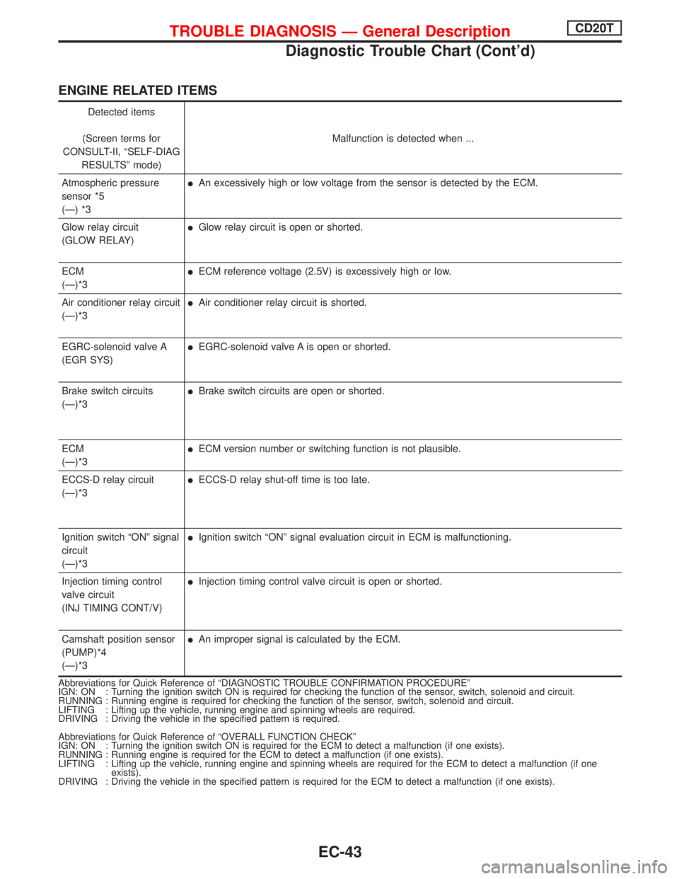
ENGINE RELATED ITEMS
Detected items
(Screen terms for
CONSULT-II, ªSELF-DIAG
RESULTSº mode)Malfunction is detected when ...
Atmospheric pressure
sensor *5
(Ð) *3
lAn excessively high or low voltage from the sensor is detected by the ECM.
Glow relay circuit
(GLOW RELAY)
lGlow relay circuit is open or shorted.
ECM
(Ð)*3
lECM reference voltage (2.5V) is excessively high or low.
Air conditioner relay circuit
(Ð)*3
lAir conditioner relay circuit is shorted.
EGRC-solenoid valve A
(EGR SYS)
lEGRC-solenoid valve A is open or shorted.
Brake switch circuits
(Ð)*3
lBrake switch circuits are open or shorted.
ECM
(Ð)*3
lECM version number or switching function is not plausible.
ECCS-D relay circuit
(Ð)*3
lECCS-D relay shut-off time is too late.
Ignition switch ªONº signal
circuit
(Ð)*3
lIgnition switch ªONº signal evaluation circuit in ECM is malfunctioning.
Injection timing control
valve circuit
(INJ TIMING CONT/V)
lInjection timing control valve circuit is open or shorted.
Camshaft position sensor
(PUMP)*4
(Ð)*3
lAn improper signal is calculated by the ECM.
Abbreviations for Quick Reference of ªDIAGNOSTIC TROUBLE CONFIRMATION PROCEDUREº
IGN: ON : Turning the ignition switch ON is required for checking the function of the sensor, switch, solenoid and circuit.
RUNNING : Running engine is required for checking the function of the sensor, switch, solenoid and circuit.
LIFTING : Lifting up the vehicle, running engine and spinning wheels are required.
DRIVING : Driving the vehicle in the specified pattern is required.
Abbreviations for Quick Reference of ªOVERALL FUNCTION CHECKº
IGN: ON : Turning the ignition switch ON is required for the ECM to detect a malfunction (if one exists).
RUNNING : Running engine is required for the ECM to detect a malfunction (if one exists).
LIFTING : Lifting up the vehicle, running engine and spinning wheels are required for the ECM to detect a malfunction (if one
exists).
DRIVING : Driving the vehicle in the specified pattern is required for the ECM to detect a malfunction (if one exists).
TROUBLE DIAGNOSIS Ð General DescriptionCD20T
Diagnostic Trouble Chart (Cont'd)
EC-43