warning NISSAN PRIMERA 1999 Electronic Owner's Manual
[x] Cancel search | Manufacturer: NISSAN, Model Year: 1999, Model line: PRIMERA, Model: NISSAN PRIMERA 1999Pages: 2267, PDF Size: 35.74 MB
Page 164 of 2267

Removal
WARNING:
Clean brake pads with a vacuum dust collector to minimize
the hazard of airborne particles or other materials.
1. Remove brake cable lock spring.
2. Release parking brake control lever, then disconnect cable
from the caliper.
3. Remove torque member fixing bolts and connecting bolt.
4. Remove brake hose connecting bolt.
5. Plug off the brake hose and cylinder body to prevent air
entering the system.
CAUTION:
Care should be taken as not to let:
lAir enter the cylinder body and brake hose.
lBrake fluid spill from the cylinder body and brake hose.
Disassembly
Remove pin bolts and pins.
NOTE:
Cylinder body can not be disassembled.
Inspection
CALIPER
CAUTION:
Do not drain any brake fluid from cylinder body. Cylinder
body can not be disassembled.
Cylinder Body
Check cylinder body for score, rust, wear, damage or presence
of foreign materials. If any of the above conditions are observed,
replace cylinder body.
Torque Member
Check for wear, cracks or other damage. Replace if necessary.
Pin and Pin Boot
Check for wear, cracks or other damage.
Replace if any of the above conditions are observed.
NBR427
REAR DISC BRAKE TYPE 2
BR-42
Page 166 of 2267

Components
1. Boot
2. Piston
3. Piston cap
4. Spring
5. Wheel cylinder6. Shoe hold-down pin
7. Plug
8. Brake drum
9. Shoe hold-down spring
10. Adjuster11. Retainer ring
12. Return spring (Upper)
13. Return spring (Lower)
14. Spring
15. Toggle lever
Removal
WARNING:
Clean brake lining with a vacuum dust collector to minimize
the hazard of airborne materials.
CAUTION:
Make sure parking brake lever is completely released.
SBR616E
REAR DRUM BRAKE
BR-44
Page 170 of 2267
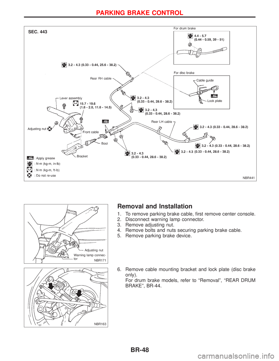
Removal and Installation
1. To remove parking brake cable, first remove center console.
2. Disconnect warning lamp connector.
3. Remove adjusting nut.
4. Remove bolts and nuts securing parking brake cable.
5. Remove parking brake device.
6. Remove cable mounting bracket and lock plate (disc brake
only).
For drum brake models, refer to ªRemovalº, ªREAR DRUM
BRAKEº, BR-44.
NBR441
NBR171 Adjusting nut
Warning lamp connec-
tor
NBR163
PARKING BRAKE CONTROL
BR-48
Page 171 of 2267
Inspection
1. Check control lever for wear or other damage. Replace if
necessary.
2. Check wires for discontinuity or deterioration. Replace if nec-
essary.
3. Check warning lamp and switch. Replace if necessary.
4. Check parts at each connecting portion and, if found
deformed or damaged, replace the parts.
Adjustment
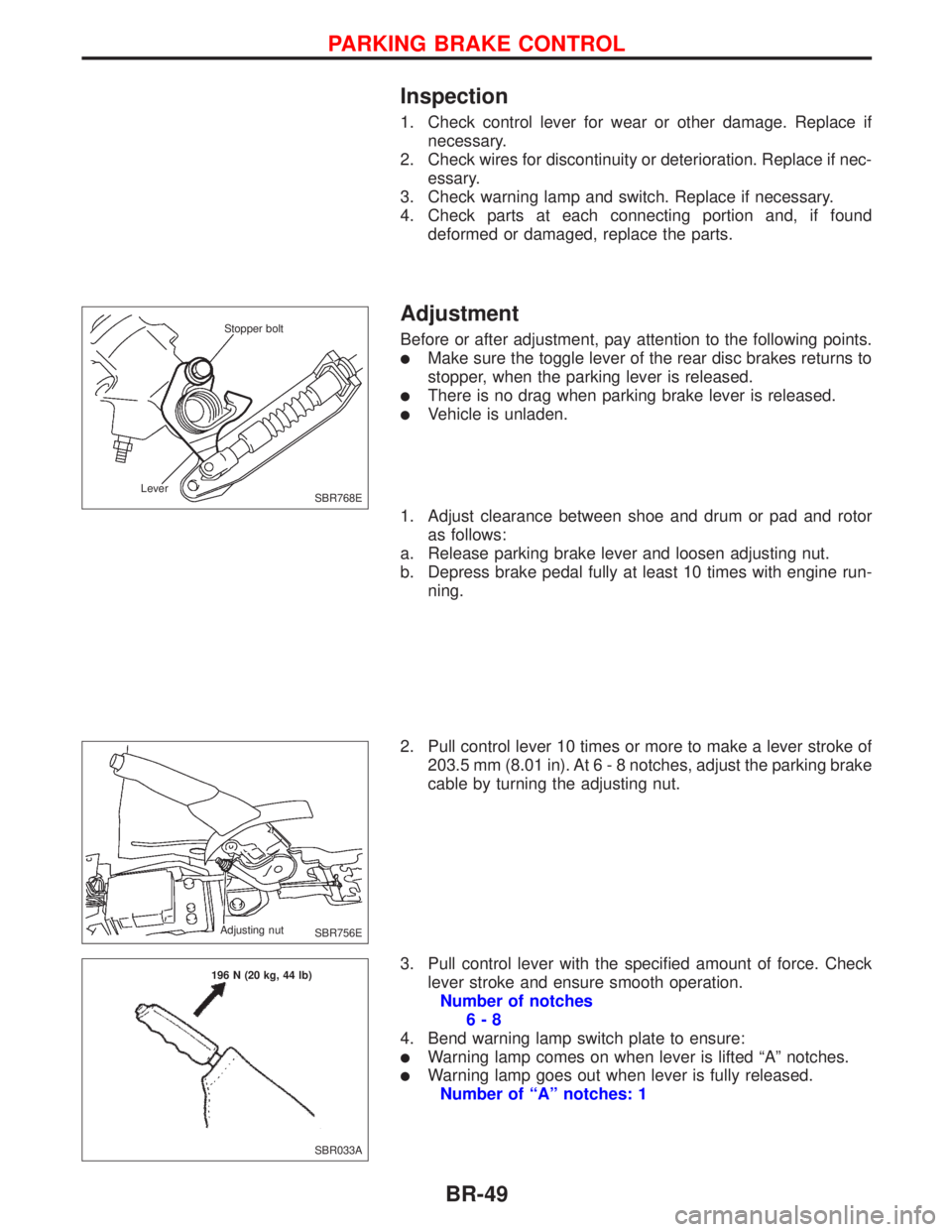
Before or after adjustment, pay attention to the following points.
lMake sure the toggle lever of the rear disc brakes returns to
stopper, when the parking lever is released.
lThere is no drag when parking brake lever is released.
lVehicle is unladen.
1. Adjust clearance between shoe and drum or pad and rotor
as follows:
a. Release parking brake lever and loosen adjusting nut.
b. Depress brake pedal fully at least 10 times with engine run-
ning.
2. Pull control lever 10 times or more to make a lever stroke of
203.5 mm (8.01 in). At6-8notches, adjust the parking brake
cable by turning the adjusting nut.
3. Pull control lever with the specified amount of force. Check
lever stroke and ensure smooth operation.
Number of notches
6-8
4. Bend warning lamp switch plate to ensure:
lWarning lamp comes on when lever is lifted ªAº notches.
lWarning lamp goes out when lever is fully released.
Number of ªAº notches: 1
SBR768E Stopper bolt
Lever
SBR756E Adjusting nut
SBR033A 196 N (20 kg, 44 lb)
PARKING BRAKE CONTROL
BR-49
Page 172 of 2267
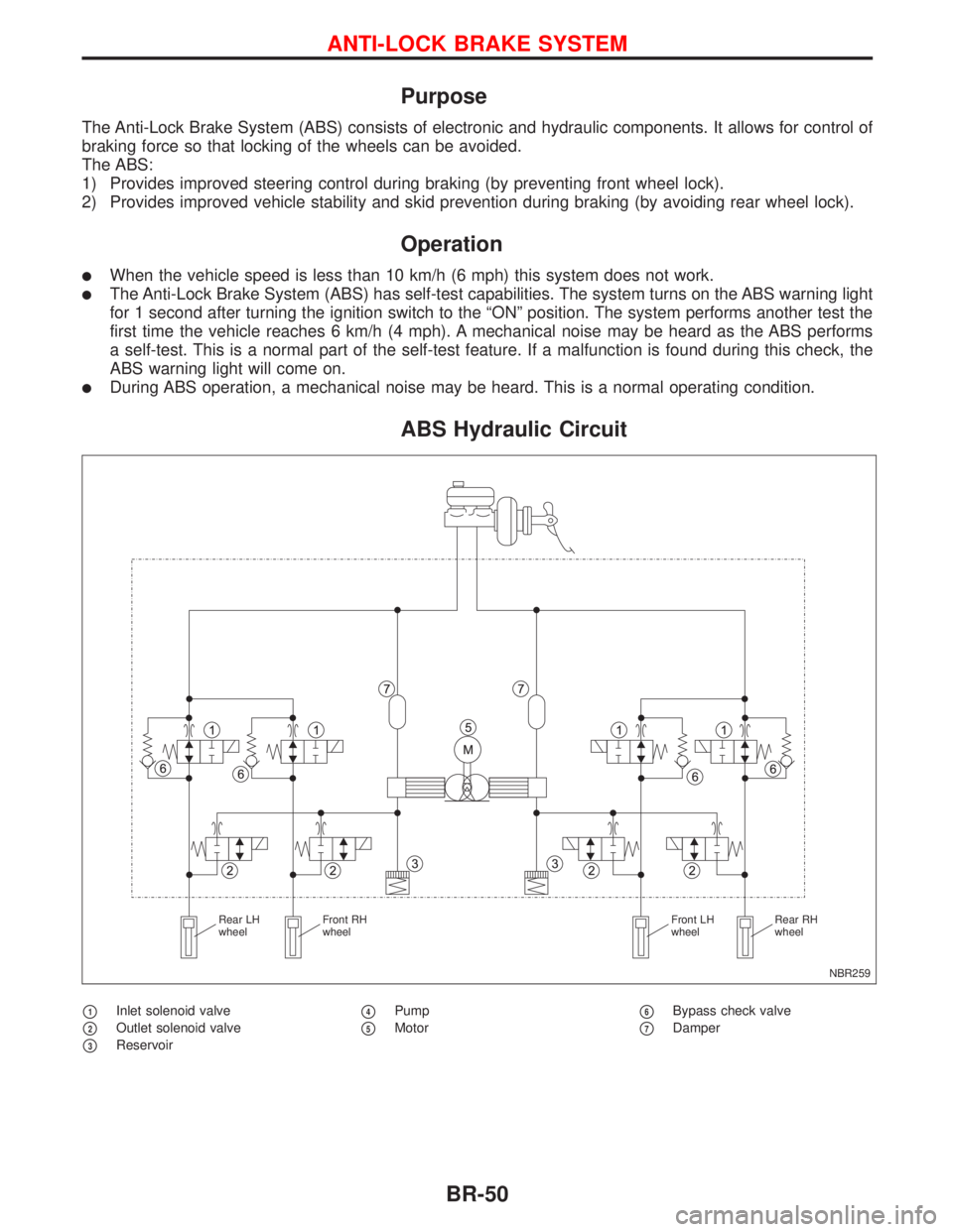
Purpose
The Anti-Lock Brake System (ABS) consists of electronic and hydraulic components. It allows for control of
braking force so that locking of the wheels can be avoided.
The ABS:
1) Provides improved steering control during braking (by preventing front wheel lock).
2) Provides improved vehicle stability and skid prevention during braking (by avoiding rear wheel lock).
Operation
lWhen the vehicle speed is less than 10 km/h (6 mph) this system does not work.
lThe Anti-Lock Brake System (ABS) has self-test capabilities. The system turns on the ABS warning light
for 1 second after turning the ignition switch to the ªONº position. The system performs another test the
first time the vehicle reaches 6 km/h (4 mph). A mechanical noise may be heard as the ABS performs
a self-test. This is a normal part of the self-test feature. If a malfunction is found during this check, the
ABS warning light will come on.
lDuring ABS operation, a mechanical noise may be heard. This is a normal operating condition.
ABS Hydraulic Circuit
p1Inlet solenoid valve
p2Outlet solenoid valve
p3Reservoir
p4Pump
p5Motorp6Bypass check valve
p7Damper
NBR259 Rear LH
wheelFront RH
wheelFront LH
wheelRear RH
wheel
ANTI-LOCK BRAKE SYSTEM
BR-50
Page 173 of 2267
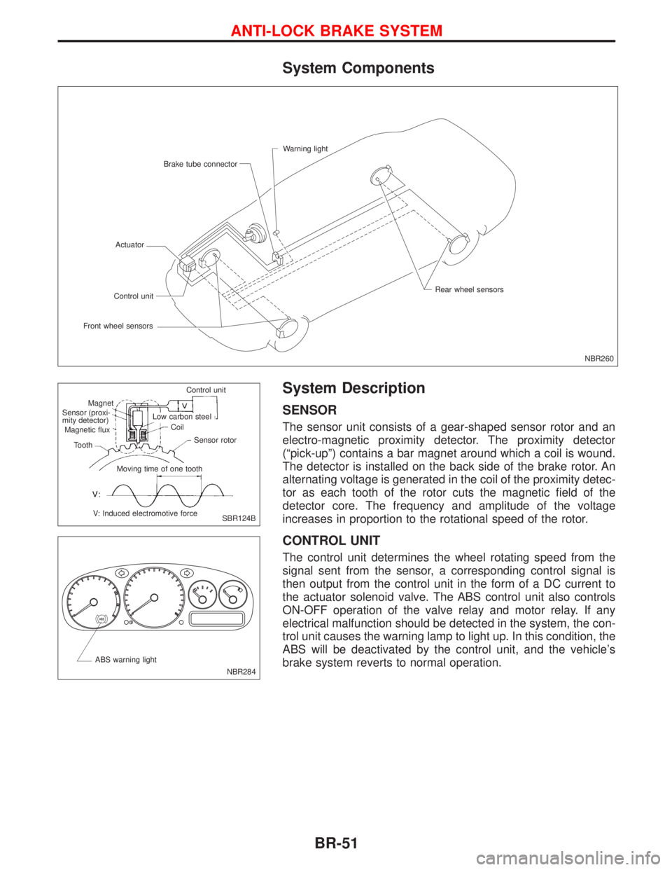
System Components
System Description
SENSOR
The sensor unit consists of a gear-shaped sensor rotor and an
electro-magnetic proximity detector. The proximity detector
(ªpick-upº) contains a bar magnet around which a coil is wound.
The detector is installed on the back side of the brake rotor. An
alternating voltage is generated in the coil of the proximity detec-
tor as each tooth of the rotor cuts the magnetic field of the
detector core. The frequency and amplitude of the voltage
increases in proportion to the rotational speed of the rotor.
CONTROL UNIT
The control unit determines the wheel rotating speed from the
signal sent from the sensor, a corresponding control signal is
then output from the control unit in the form of a DC current to
the actuator solenoid valve. The ABS control unit also controls
ON-OFF operation of the valve relay and motor relay. If any
electrical malfunction should be detected in the system, the con-
trol unit causes the warning lamp to light up. In this condition, the
ABS will be deactivated by the control unit, and the vehicle's
brake system reverts to normal operation.
NBR260 Warning light
Brake tube connector
Actuator
Front wheel sensorsControl unitRear wheel sensors
SBR124B Control unit
Magnet
.Sensor (proxi-
mity detector)
Magnetic flux
Tooth
V: Induced electromotive forceMoving time of one toothSensor rotor Coil Low carbon steel
NBR284 ABS warning light
ANTI-LOCK BRAKE SYSTEM
BR-51
Page 181 of 2267

Preliminary Check
Check brake fluid level in reservoir
tank.
------------------------------------------------------------------------------------------------------------------------------------------------------------------------------------------------------------------------------------------------------------------------------------------------------------
Low fluid level may indicate brake pad
wear or leakage from brake line.
Check brake line for leakage.
OK
ENG
Repair.
F
Check brake booster for operation and
air tightness. Refer to BR-18.
OK
ENG
Replace.
F
Check brake pads and rotor. Refer to
BR-23, 26, 33.
OK
ENG
Replace.
Check brake fluid level in reservoir tank.
OK
ENG
Fill up brake fluid.
Check warning lamp activation.
When ignition switch is turned on,
warning lamp turns on.
OK
ENG
Check fuse, warning
lamp bulb and warning
lamp circuit.
Check warning lamp for deactivation.
When ignition switch is turned on,
warning lamp turns on, then deacti-
vates after 1 second.
OK
ENG
Go to Self-diagnosis,
BR-67 and BR-70.
Drive vehicle at 30 km/h (19 mph) for
at least one minute.
Ensure warning lamp remains off while
driving.
OK
ENG
Go to Self-diagnosis,
BR-67 and BR-70.
END
NBR141 MAX.
MIN.
SBR389C
SBR058C
SBR059C
.
NBR284 ABS warning light
H
H
H
H
H
H
H
H
H
TROUBLE DIAGNOSES
BR-59
Page 182 of 2267
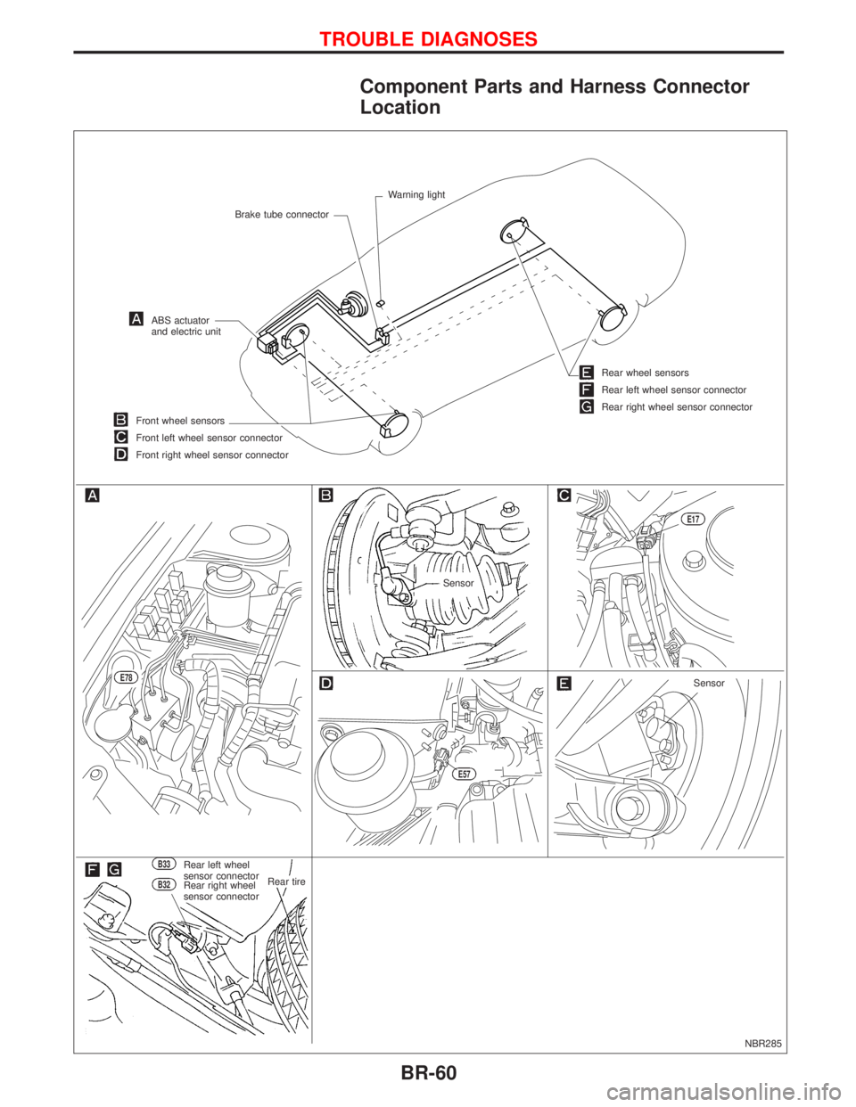
Component Parts and Harness Connector
Location
NBR285
Brake tube connectorWarning light
ABS actuator
and electric unit
Front wheel sensors
Front left wheel sensor connector
Front right wheel sensor connector
Sensor
E17
Rear wheel sensors
Rear left wheel sensor connector
Rear right wheel sensor connector
B33Rear left wheel
sensor connector
B32Rear right wheel
sensor connector.Rear tire
.E78
E57
Sensor
TROUBLE DIAGNOSES
BR-60
Page 184 of 2267

Wiring Diagram Ð ABS Ð
MODELS WITH SELF-DIAGNOSIS FUNCTION
YBR208 BATTERYIGNITION SWITCH
ON or START
FUSE
BLOCK
(J/B)Refer to EL-POWER.
: LHD models
: RHD models: CVT models
: M/T models
RELEASEDDEPRESSEDSTOP LAMP
SWITCH
FUSE
BLOCK
(J/B)COMBINATION METER
(ABS WARNING LAMP)
ABS ACTUATOR
AND ELECTRIC
UNIT
(CONTROL UNIT)
TCM
(TRANSMISSION CON-
TROL MODULE)DATA LINK CON-
NECTOR
Refer to las page (Foldout page).
TROUBLE DIAGNOSES
BR-62
Page 189 of 2267

Self-diagnosis (Only models with data link
connector terminal No. 8)
FUNCTION
lWhen a problem occurs in the ABS, the warning lamp on the
instrument panel comes on. To start the self-diagnostic
results mode, ground the self-diagnostic (check) terminal
located on ªData Link Connector for CONSULT-IIº. The loca-
tion of the malfunction is indicated by the warning lamp flash-
ing.
SELF-DIAGNOSIS PROCEDURE
Drive vehicle over 30 km/h (19 mph) for at
least one minute.
Turn ignition switch to the ªLOCKº position.
Ground terminal ª8º of ªDATA LINK CON-
NECTOR for CONSULT-IIº with a suitable
harness.
Turn ignition switch to ªONº position while
grounding terminal ª8º.
Do not depress brake pedal.
After 3.0 seconds, the warning lamp starts
flashing to indicate the malfunction code
No. (See NOTE.)
Verify the location of the malfunction with
the malfunction code chart. Refer to BR-69.
Then make the necessary repairs following
the diagnostic procedures.
After the malfunctions are repaired, erase
the malfunction codes stored in the control
unit. Refer to BR-68.
Rerun the self-diagnostic results mode to
verify that the malfunction codes have been
erased.
NOTE: The indication ter-
minates after five
minutes.
However, when the
ignition switch is
turned from off to
on, the indication
starts flashing
again. Disconnect the check terminal from the
ground. The self-diagnostic results mode is
now complete.
pA
NBR295
.DATA link connector for
CONSULT-II
(Ground terminal 8 with
a suitable harness.)
NBR284 ABS warning light
NBR305
.DATA link connector
for CONSULT-II
(Disconnect the har-
ness)
H
H
H
H
H
H
H
H
H
TROUBLE DIAGNOSES
BR-67