audio NISSAN PRIMERA 1999 Electronic Owner's Guide
[x] Cancel search | Manufacturer: NISSAN, Model Year: 1999, Model line: PRIMERA, Model: NISSAN PRIMERA 1999Pages: 2267, PDF Size: 35.74 MB
Page 1947 of 2267
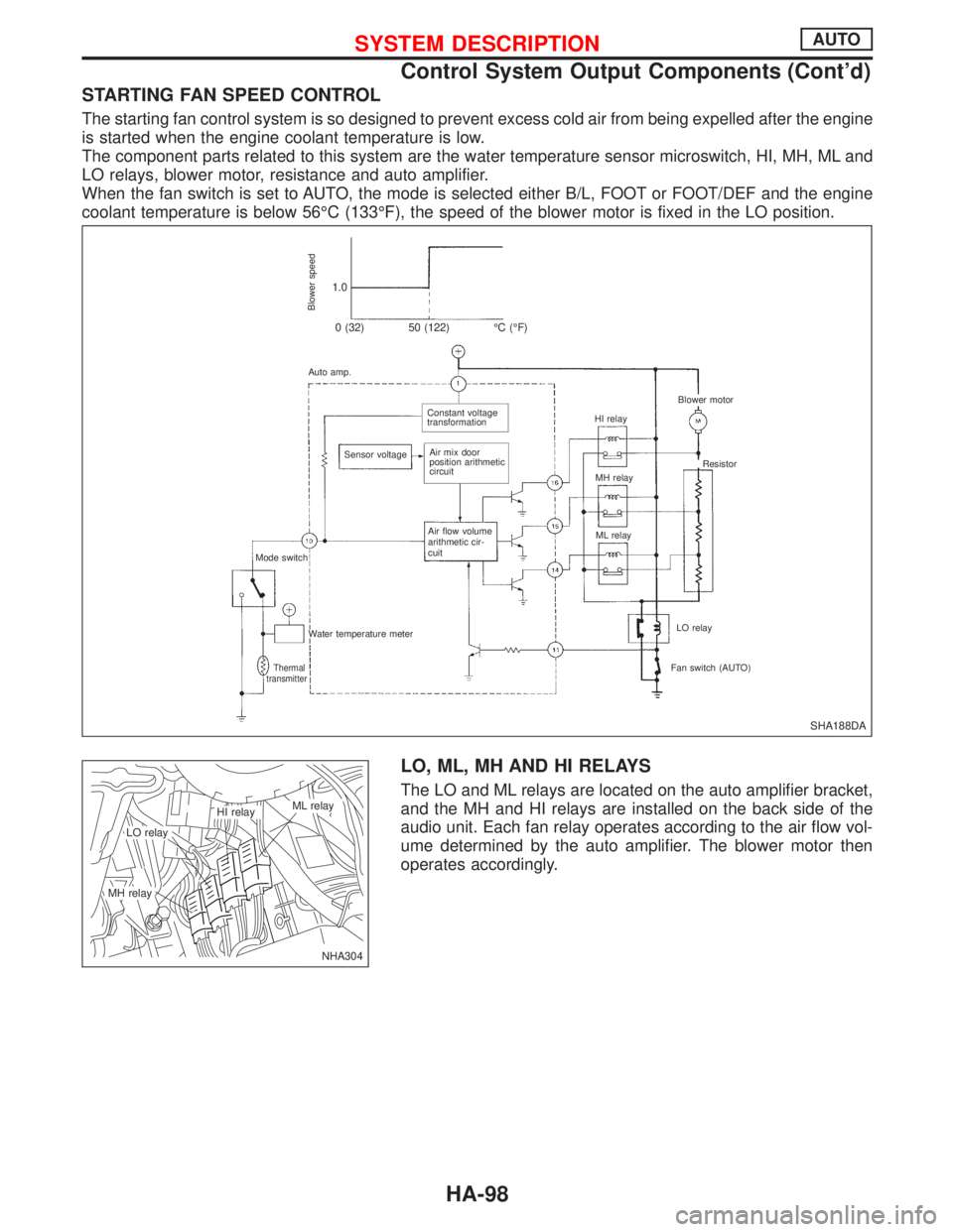
STARTING FAN SPEED CONTROL
The starting fan control system is so designed to prevent excess cold air from being expelled after the engine
is started when the engine coolant temperature is low.
The component parts related to this system are the water temperature sensor microswitch, HI, MH, ML and
LO relays, blower motor, resistance and auto amplifier.
When the fan switch is set to AUTO, the mode is selected either B/L, FOOT or FOOT/DEF and the engine
coolant temperature is below 56ÉC (133ÉF), the speed of the blower motor is fixed in the LO position.
LO, ML, MH AND HI RELAYS
The LO and ML relays are located on the auto amplifier bracket,
and the MH and HI relays are installed on the back side of the
audio unit. Each fan relay operates according to the air flow vol-
ume determined by the auto amplifier. The blower motor then
operates accordingly.
SHA188DA
Blower speed
1.0
0 (32) 50 (122) ÉC (ÉF)
Auto amp.
.Constant voltage
transformation
Sensor voltage
.Air mix door
position arithmetic
circuit
Air flow volume
arithmetic cir-
cuit
Mode switch
Water temperature meter
Thermal
transmitterFan switch (AUTO)LO relay ML relay MH relay HI relay
.Blower motor
Resistor
NHA304
.LO relay
.ML relay.HI relay
.MH relay
SYSTEM DESCRIPTIONAUTO
Control System Output Components (Cont'd)
HA-98
Page 1969 of 2267
A
AAC/V - Wiring diagram....EC-QG-276, EC-SR-265
ABS (anti-lock brake system).........................BR-50
A/C control linkage adjustment (manual
A/C) .............................................................HA-82
A/C control operation (auto A/C) ....................HA-19
A/C diagnostic work flow (auto A/C) ..............HA-26
A/C performance chart ...................................HA-35
A/C performance test diagnoses....................HA-33
A/C relay.........................................................HA-78
A/C service data specification ......................HA-118
A/C switch ......................................................HA-78
A/C symptom chart (auto A/C) .......................HA-28
A/C trouble diagnoses (auto A/C) ..................HA-26
Accelerator control system ...............................FE-3
Accelerator position sensor ...................EC-CD-108
Accelerator position switch ....................EC-CD-108
Accelerator wire adjustment .............................FE-4
A/CCUT - Wiring diagram ......................EC-CD-127
Air bag disposal..............................................RS-27
Air bag precautions ...........................................GI-3
Air bleeding for brake system ..........................BR-8
Air cleaner filter replacement ............MA-23, 34, 44
Air conditioner cut
control .....EC-QG-24, EC-SR-26, EC-CD-20, 126
Air flow meter - See Mass air flow
sensor ............................EC-QG-110, EC-SR-120
Air mix. door motor.........................................HA-92
Alternator ..................................................EL-53, 56
Ambient sensor ..............................................HA-86
Antenna .........................................................EL-229
Anti-lock brake system - See ABS .................BR-50
APS - Wiring diagram ............................EC-CD-109
A/T - Wiring diagram - AT - FTS .....................AT-56
A/T - Wiring diagram - AT - MAIN ...................AT-45
A/T - Wiring diagram - AT - PNP/SW..............AT-50
A/T - Wiring diagram - AT - VSS A/T ..............AT-64
A/T diagnosis communication line .........EC-SR-295
A/T fluid temperature sensor...........................AT-54
A/T trouble diagnoses ...............................AT-29, 30
A/T Wiring diagram - AT - ENG SS ................AT-67
A/T Wiring diagram AT - LPSV .......................AT-76
A/T Wiring diagram AT - TCV .........................AT-71
A/T Wiring diagram AT - TPS..........................AT-81
ATDIAG - Wiring diagram ......................EC-SR-296
Audio .............................................................EL-216
AUDIO - Wiring diagram ...............................EL-219
Audio and A/C control removal and
installation - See Instrument panel .............BT-15
Auto air conditioner - Wiring diagram ............HA-42
Automatic amplifier .........................................HA-87
Automatic transaxle number............................GI-44
Automatic transmission fluid
replacement..........................................MA-49, 50
Auxiliary air control (AAC)
valve ..............................EC-QG-274, EC-SR-263BBack door opener - See Back door ............BT-9, 11
Back door trim.................................................BT-30
Back door window ....................................BT-35, 56
Back-up lamp ................................................EL-107
BACK/L - Wiring diagram..............................EL-107
Ball joint front axle ....................................FA-32, 33
Base idle air volume
initialiging ...........................EC-QG-33, EC-SR-46
Basic inspection ....................EC-QG-72, EC-SR-84
Battery .............................................................EL-29
Body alignment ...............................................BT-60
Brake booster .................................................BR-18
Brake control valve (Proportioning
valve)...........................................................BR-11
Brake fluid change ...........................................BR-7
Brake fluid level .............................................MA-51
Brake fluid level and line check .......................BR-7
Brake hydraulic line ..........................................BR-9
Brake inspection ............................................MA-51
Brake lining wear temporary checking ..........MA-51
Brake pedal ....................................................BR-13
Bulb specifications ........................................EL-137
Bumper, front ....................................................BT-5
Bumper, rear .......................................BT-5, 7, 9, 11
BUZZER - Wiring diagram ............................EL-181
C
Camshaft inspection ...............EM-35, 91, 138, 147,
183, 192, 196
Camshaft position sensor
(CMPS) ..........................EC-QG-238, EC-SR-239
Camshaft position sensor (PHASE) ......EC-QG-238
Canister-See EVAP
canister ..............................EC-QG-25, EC-SR-27
CHARGE - Wiring diagram .............................EL-53
Charging system .............................................EL-53
Chassis and body maintenance ....................MA-48
CHIME - Wiring diagram ...............................EL-181
Cigarette lighter.............................................EL-203
Circuit breaker.................................................EL-22
CKPS - Wiring diagram....EC-QG-234, EC-SR-236,
292, EC-CD-115
Clock .............................................................EL-203
Closed throttle position switch ...............EC-SR-271
Clutch cover ....................................................CL-13
Clutch damper ................................................CL-10
Clutch disc ......................................................CL-13
Clutch fluid level.............................................MA-48
Clutch master cylinder ......................................CL-8
Clutch operating cylinder ..................................CL-9
Clutch release mechanism..............................CL-11
CMPS - Wiring diagram ....EC-QG-240, EC-SR-242
Coil spring (rear) .............................................RA-11
Collision diagnosis..........................................RS-57
Combination meter........................................EL-138
ALPHABETICAL INDEX
IDX-2
Page 2197 of 2267

REMOVAL SATELLITE SENSOR
1. Remove seat belt pre-tensioner. Refer to ªFront Seat Beltº for
details. (RS-3)
2. Disconnect satellite sensor connector.
3. Remove bolt and nuts from satellite sensor unit. Then
remove the satellite sensor.
NOTE:
lTo install, reverse the removal procedure sequence.
Removal Ð Air Bag Module and Spiral Cable
NRS126
7-13
(0.8 - 1.3,
62 - 115)
14.5 - 24.5
(1.5 - 2.5,
11 - 18)
.Ground bolt2.94 - 4.9
(0.30 - 0.50,
26 - 43)
: N´m (kg-m, ft-lb)
: N´m (kg-m, in-lb)Connector
NRS123 Side lid RH
(where fitted) Audio steering switch
(where fitted)
Side lid RH
29-39N´m
(3.0 - 4.0 kg-m, 22 - 29 ft-lb) Spiral
cable
Combination switch
Side lid LHSpecial bolt
7.8 - 13.7 N´m (0.8 - 1.4 kg-m, 69 - 121 in-lb)Lower lid
SEC. 253×484
Air bag module Special bolt
7.8 - 13.7 N´m (0.8 - 1.4 kg-m, 69 - 121 in-lb)
SUPPLEMENTAL RESTRAINT SYSTEM (SRS)
Removal and Installation Ð Diagnosis
Sensor Unit, Seat Belt Pre-tensioner and
Satellite Sensor (Cont'd)
RS-14