change wheel NISSAN PRIMERA 1999 Electronic Repair Manual
[x] Cancel search | Manufacturer: NISSAN, Model Year: 1999, Model line: PRIMERA, Model: NISSAN PRIMERA 1999Pages: 2267, PDF Size: 35.74 MB
Page 15 of 2267
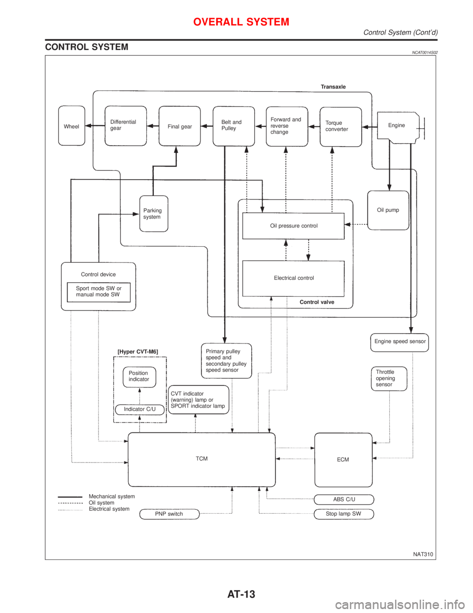
CONTROL SYSTEMNCAT0014S02
NAT310 WheelDifferential
gearFinal gearBelt and
PulleyForward and
reverse
changeTorque
converterEngine Transaxle
Oil pump
Oil pressure control Parking
system
Control device
Sport mode SW or
manual mode SWElectrical control
Control valve
Primary pulley
speed and
secondary pulley
speed sensor
CVT indicator
(warning) lamp or
SPORT indicator lamp [Hyper CVT-M6]
Position
indicator
Indicator C/U
TCM
Mechanical system
Oil system
Electrical system
Stop lamp SWABS C/UECMThrottle
opening
sensor Engine speed sensor
PNP switch
OVERALL SYSTEM
Control System (Cont'd)
AT-13
Page 63 of 2267
Diagnostic ProcedureNCAT0222
1 CHECK PRIMARY SPEED SENSOR
Refer to ªComponent Inspectionº AT-65.
OK or NG
OK (With CONSULT-II)©GO TO 2.
OK (Without CONSULT-II)©GO TO 3.
NG©Repair or replace primary speed sensor.
2 CHECK INPUT SIGNAL (With CONSULT-II)
With CONSULT-II
1. Start engine.
2. Select ªECU INPUT SIGNALSº in ªDATA MONITORº mode for ªCVTº with CONSULT-II.
3. Read out the value of ªI/P PULLY SPDº while driving.
Check the value changes according to driving speed. (Almost same value as engine speed)
OK or NG
OK©GO TO 4.
NG©Check the following items:
IHarness for short or open between TCM, ECM and primary speed sensor (Main har-
ness)
IGround circuit for ECM
Refer to EC section (ªTROUBLE DIAGNOSIS FOR POWER SUPPLYº).
3 CHECK DTC
Perform Diagnostic Trouble Code (DTC) confirmation procedure, AT-62.
OK or NG
OK©INSPECTION END
NG©1. Perform TCM input/output signal inspection.
2. If NG, recheck TCM pin terminals for damage or loose connection with harness con-
nector.
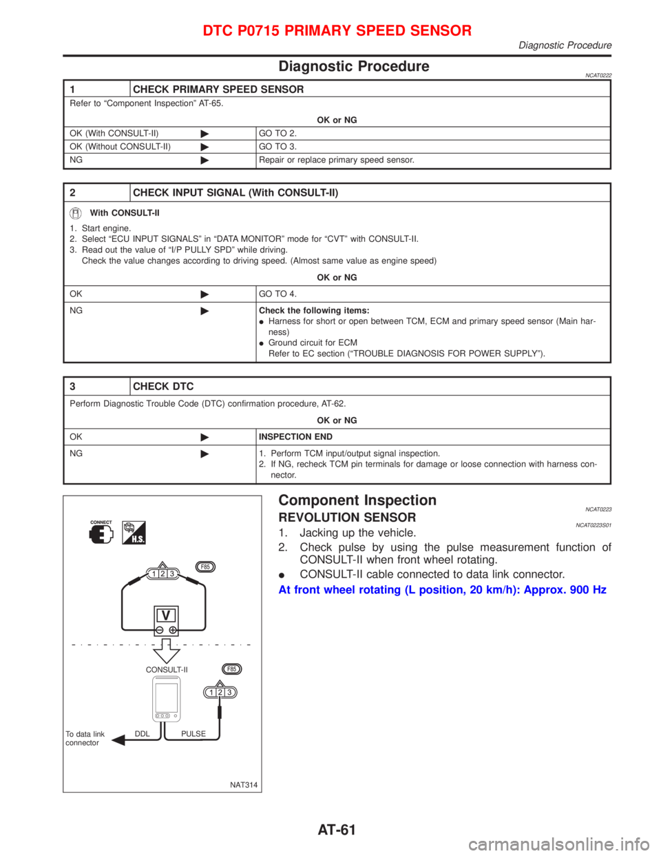
Component InspectionNCAT0223REVOLUTION SENSORNCAT0223S011. Jacking up the vehicle.
2. Check pulse by using the pulse measurement function of
CONSULT-II when front wheel rotating.
ICONSULT-II cable connected to data link connector.
At front wheel rotating (L position, 20 km/h): Approx. 900 Hz
NAT314 CONSULT-II
To data link
connectorDDL PULSE
DTC P0715 PRIMARY SPEED SENSOR
Diagnostic Procedure
AT-61
Page 67 of 2267
Diagnostic ProcedureNCAT0039
1 CHECK SECONDARY SPEED SENSOR
Refer to ªComponent Inspectionº AT-65.
OK or NG
OK (With CONSULT-II)©GO TO 2.
OK (Without CONSULT-II)©GO TO 3.
NG©Repair or replace secondary speed sensor.
2 CHECK INPUT SIGNAL (With CONSULT-II)
With CONSULT-II
1. Start engine.
2. Select ªECU INPUT SIGNALSº in ªDATA MONITORº mode for ªCVTº with CONSULT-II.
3. Read out the value of ªVEHICLE SPEEDº while driving.
Check the value changes according to driving speed.
OK or NG
OK©GO TO 4.
NG©Check the following items:
IHarness for short or open between TCM, ECM and secondary speed sensor (Main
harness)
IGround circuit for ECM
Refer to EC section (ªTROUBLE DIAGNOSIS FOR POWER SUPPLYº).
3 CHECK DTC
Perform Diagnostic Trouble Code (DTC) confirmation procedure, AT-62.
OK or NG
OK©INSPECTION END
NG©1. Perform TCM input/output signal inspection.
2. If NG, recheck TCM pin terminals for damage or loose connection with harness con-
nector.
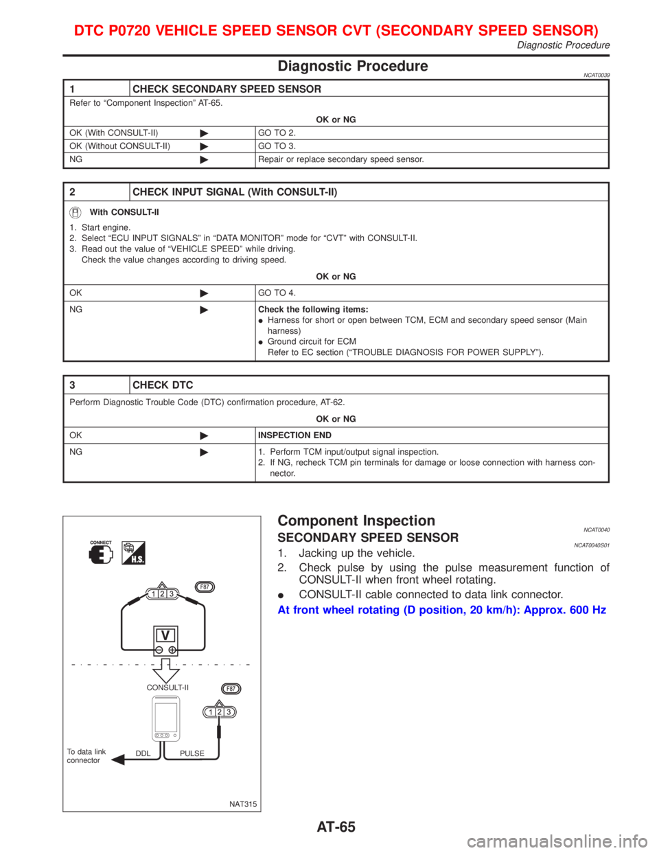
Component InspectionNCAT0040SECONDARY SPEED SENSORNCAT0040S011. Jacking up the vehicle.
2. Check pulse by using the pulse measurement function of
CONSULT-II when front wheel rotating.
ICONSULT-II cable connected to data link connector.
At front wheel rotating (D position, 20 km/h): Approx. 600 Hz
NAT315 CONSULT-II
DDL PULSE To data link
connector
DTC P0720 VEHICLE SPEED SENSOR CVT (SECONDARY SPEED SENSOR)
Diagnostic Procedure
AT-65
Page 159 of 2267
Pin and Pin Boot
Check for wear, cracks or other damage.
Replace if any of the above conditions are observed.
Rotor
Rubbing Surface
Check rotor for roughness, cracks or chips.
Runout
1. Secure rotor to wheel hub with two nuts (M12 x 1.25).
2. Check runout using a dial indicator.
Make sure that axial end play is within the specifications
before measuring. Refer to RA section (ªREAR WHEEL
BEARINGº, ªOn-vehicle Serviceº).
3. Change relative positions of rotor and wheel hub so that
runout is minimized.
Maximum runout:
0.07 mm (0.0028 in)
Thickness
Rotor repair limit:
Standard thickness
10 mm (0.39 in)
Minimum thickness
9 mm (0.35 in)
Thickness variation (At least 8 portions)
Maximum 0.02 mm (0.0008 in)
Assembly
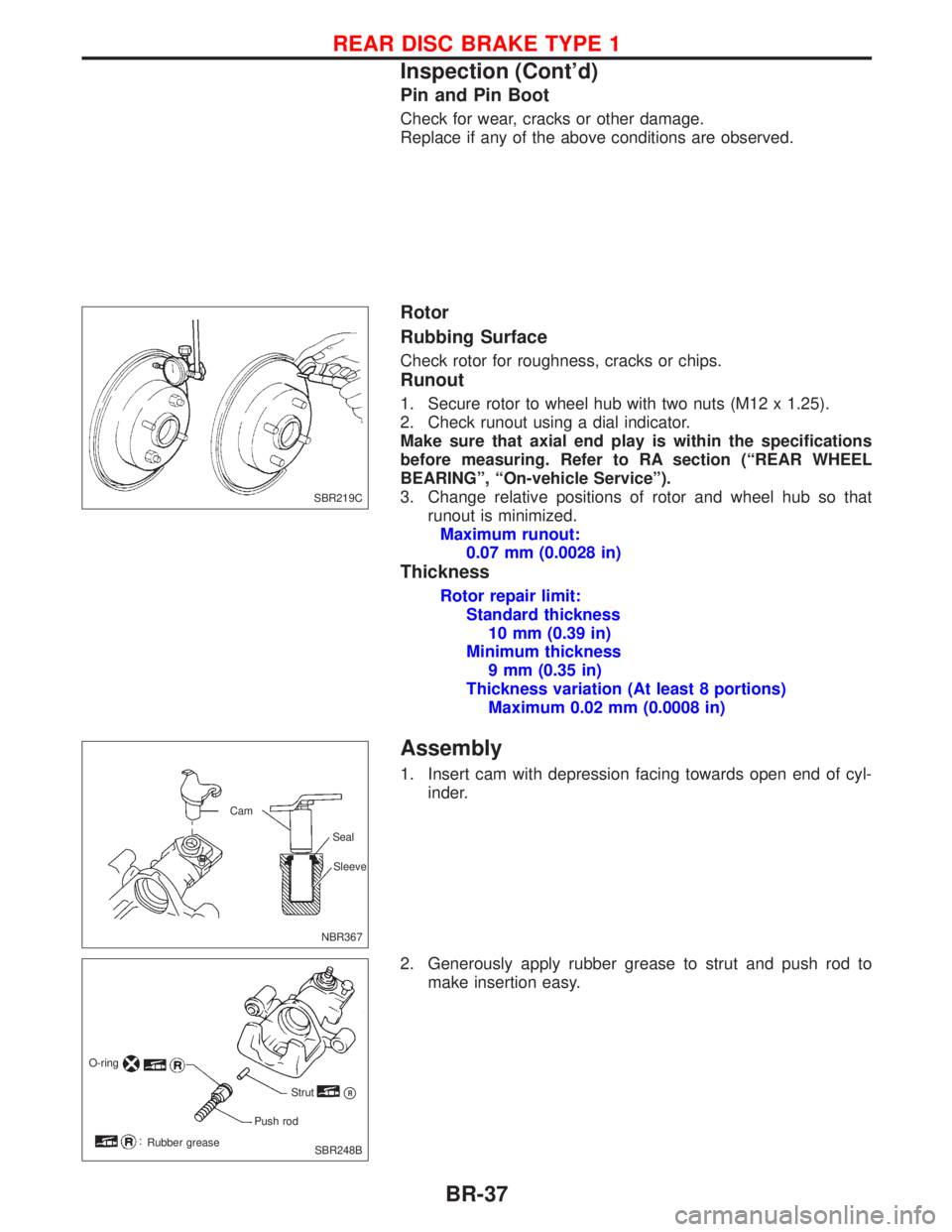
1. Insert cam with depression facing towards open end of cyl-
inder.
2. Generously apply rubber grease to strut and push rod to
make insertion easy.
SBR219C
NBR367Sleeve Seal Cam
O-ring
Strut
pR
Push rod
Rubber grease
SBR248B
REAR DISC BRAKE TYPE 1
Inspection (Cont'd)
BR-37
Page 165 of 2267
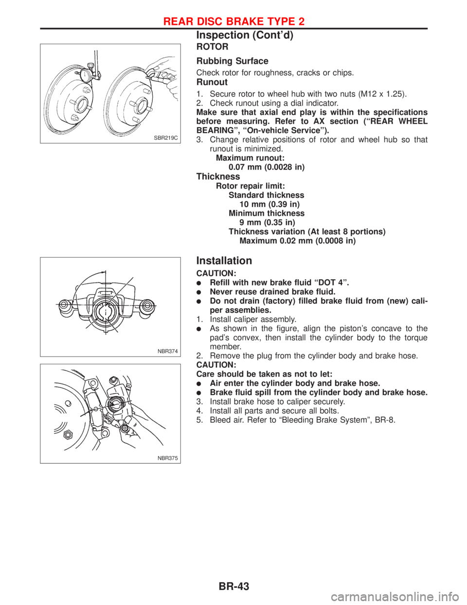
ROTOR
Rubbing Surface
Check rotor for roughness, cracks or chips.
Runout
1. Secure rotor to wheel hub with two nuts (M12 x 1.25).
2. Check runout using a dial indicator.
Make sure that axial end play is within the specifications
before measuring. Refer to AX section (ªREAR WHEEL
BEARINGº, ªOn-vehicle Serviceº).
3. Change relative positions of rotor and wheel hub so that
runout is minimized.
Maximum runout:
0.07 mm (0.0028 in)
Thickness
Rotor repair limit:
Standard thickness
10 mm (0.39 in)
Minimum thickness
9 mm (0.35 in)
Thickness variation (At least 8 portions)
Maximum 0.02 mm (0.0008 in)
Installation
CAUTION:
lRefill with new brake fluid ªDOT 4º.
lNever reuse drained brake fluid.
lDo not drain (factory) filled brake fluid from (new) cali-
per assemblies.
1. Install caliper assembly.
lAs shown in the figure, align the piston's concave to the
pad's convex, then install the cylinder body to the torque
member.
2. Remove the plug from the cylinder body and brake hose.
CAUTION:
Care should be taken as not to let:
lAir enter the cylinder body and brake hose.
lBrake fluid spill from the cylinder body and brake hose.
3. Install brake hose to caliper securely.
4. Install all parts and secure all bolts.
5. Bleed air. Refer to ªBleeding Brake Systemº, BR-8.
SBR219C
NBR374
NBR375
REAR DISC BRAKE TYPE 2
Inspection (Cont'd)
BR-43
Page 528 of 2267
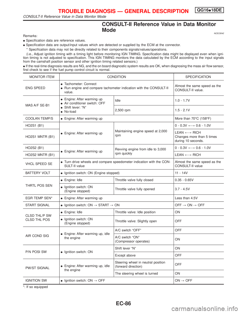
CONSULT-II Reference Value in Data Monitor
Mode
NCEC0042Remarks:
ISpecification data are reference values.
ISpecification data are output/input values which are detected or supplied by the ECM at the connector.
* Specification data may not be directly related to their components signals/values/operations.
(i.e., Adjust ignition timing with a timing light before monitoring IGN TIMING. Specification data might be displayed even when igni-
tion timing is not adjusted to specification. This IGN TIMING monitors the data calculated by the ECM according to the input signals
from the camshaft position sensor and other ignition timing related sensors.)
IIf the real-time diagnosis results are NG, and the on board diagnostic system results are OK, when diagnosing the mass air flow sensor,
first check to see if the fuel pump control circuit is normal.
MONITOR ITEM CONDITION SPECIFICATION
ENG SPEEDITachometer: Connect
IRun engine and compare tachometer indication with the CONSULT-II
value.Almost the same speed as the
CONSULT-II value.
MAS A/F SE-B1IEngine: After warming up
IAir conditioner switch: OFF
IShift lever: ªNº
INo-loadIdle 1.0 - 1.7V
2,500 rpm 1.5 - 2.1V
COOLAN TEMP/SIEngine: After warming up More than 70ÉC (158ÉF)
HO2S1 (B1)
IEngine: After warming upMaintaining engine speed at 2,000
rpm0 - 0.3V+,0.6 - 1.0V
HO2S1 MNTR (B1)LEAN+,RICH
Changes more than 5 times
during 10 seconds.
HO2S2 (B1)
IEngine: After warming upRevving engine from idle to 3,000
rpm quickly0 - 0.3V+,0.6 - 1.0V
HO2S2 MNTR (B1)LEAN+,RICH
VHCL SPEED SEITurn drive wheels and compare speedometer indication with the CON-
SULT-II valueAlmost the same speed as the
CONSULT-II value
BATTERY VOLTIIgnition switch: ON (Engine stopped) 11 - 14V
THRTL POS SENIEngine: Idle Throttle valve fully closed 0.35 - 0.65V
IIgnition switch: ON
(Engine stopped)Throttle valve fully opened 3.7 - 4.5V
EGR TEMP SEN*IEngine: After warming up Less than 4.5V
START SIGNALIIgnition switch: ON,START,ON OFF,ON,OFF
CLSD THL/P SW
CLSD THL POSIEngine: Idle Throttle valve: Idle position ON
IIgnition switch: ON
(Engine stopped)Throttle valve: Slightly open OFF
AIR COND SIGIEngine: After warming up, idle
the engineA/C switch ªOFFº OFF
A/C switch ªONº
(Compressor operates)ON
P/N POSI SWIIgnition switch: ONShift lever ªNº ON
Except above OFF
PW/ST SIGNALIEngine: After warming up, idle
the engineSteering wheel in neutral position
(forward direction)OFF
The steering wheel is turned ON
IGNITION SWIIgnition switch: ON,OFF ON,OFF
*: If so equipped
TROUBLE DIAGNOSIS Ð GENERAL DESCRIPTIONQG16I18DE
CONSULT-II Reference Value in Data Monitor Mode
EC-86
Page 704 of 2267

DescriptionNCEC0248SYSTEM DESCRIPTIONNCEC0248S01
Sensor Input Signal to ECMECM func-
tionActuator
Crankshaft position sensor (POS) Engine speed
EVAP can-
ister purge
controlEVAP canister purge volume
control solenoid valve Mass air flow sensor Amount of intake air
Engine coolant temperature sensor Engine coolant temperature
Battery Battery voltage
Ignition switch Start signal
Throttle position sensor Throttle position
Heated oxygen 1 sensorDensity of oxygen in exhaust gas
(Mixture ratio feedback signal)
Vehicle speed sensor or ABS actuator and
electric unit (control unit)Vehicle speed
This system controls flow rate of fuel vapor from the EVAP canis-
ter. The opening of the vapor by-pass passage in the EVAP canis-
ter purge volume control solenoid valve changes to control the flow
rate. The EVAP canister purge volume control solenoid valve
repeats ON/OFF operation according to the signal sent from the
ECM. The opening of the valve varies for optimum engine control.
The optimum value stored in the ECM is determined by consider-
ing various engine conditions. When the engine is operating, the
flow rate of fuel vapor from the EVAP canister is regulated as the
air flow changes.
COMPONENT DESCRIPTIONNCEC0248S02The EVAP canister purge volume control solenoid valve uses a
ON/OFF duty to control the flow rate of fuel vapor from the EVAP
canister. The EVAP canister purge volume control solenoid valve
is moved by ON/OFF pulses from the ECM. The longer the ON
pulse, the greater the amount of fuel vapor that will flow through the
valve.
CONSULT-II Reference Value in Data Monitor
Mode
NCEC0249
MONITOR ITEM CONDITION SPECIFICATION
PURG VOL C/VIEngine: After warming up
INo-load
ILift up drive wheels and shift to
1st gear position.
IAir conditioner switch ªOFFºIdle 0%
More than 2,000 rpm Ð
SEF337U
DTC P0443 EVAP CANISTER PURGE VOLUME CONTROL
SOLENOID VALVE (CIRCUIT)QG16I18DE
Description
EC-262
Page 898 of 2267
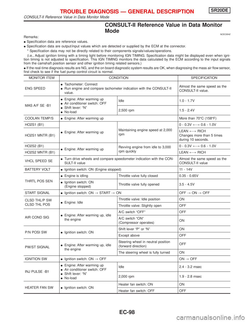
CONSULT-II Reference Value in Data Monitor
Mode
NCEC0042Remarks:
ISpecification data are reference values.
ISpecification data are output/input values which are detected or supplied by the ECM at the connector.
* Specification data may not be directly related to their components signals/values/operations.
(i.e., Adjust ignition timing with a timing light before monitoring IGN TIMING. Specification data might be displayed even when igni-
tion timing is not adjusted to specification. This IGN TIMING monitors the data calculated by the ECM according to the input signals
from the camshaft position sensor and other ignition timing related sensors.)
IIf the real-time diagnosis results are NG, and the on board diagnostic system results are OK, when diagnosing the mass air flow sensor,
first check to see if the fuel pump control circuit is normal.
MONITOR ITEM CONDITION SPECIFICATION
ENG SPEEDITachometer: Connect
IRun engine and compare tachometer indication with the CONSULT-II
value.Almost the same speed as the
CONSULT-II value.
MAS A/F SE -B1IEngine: After warming up
IAir conditioner switch: OFF
IShift lever: ªNº
INo-loadIdle 1.0 - 1.7V
2,500 rpm 1.5 - 2.4V
COOLAN TEMP/SIEngine: After warming up More than 70ÉC (158ÉF)
HO2S1 (B1)
IEngine: After warming upMaintaining engine speed at 2,000
rpm0 - 0.3V+,0.6 - 1.0V
HO2S1 MNTR (B1)LEAN+,RICH
Changes more than 5 times
during 10 seconds.
HO2S2 (B1)
IEngine: After warming upRevving engine from idle to 3,000
rpm quickly0 - 0.3V+,0.6 - 1.0V
HO2S2 MNTR (B1)LEAN+,RICH
VHCL SPEED SEITurn drive wheels and compare speedometer indication with the CON-
SULT-II valueAlmost the same speed as the
CONSULT-II value
BATTERY VOLTIIgnition switch: ON (Engine stopped) 11 - 14V
THRTL POS SENIEngine is idling Throttle valve fully closed 0.35 - 0.65V
IIgnition switch: ON
(Engine stopped)Throttle valve fully opened 3.5 - 4.5V
START SIGNALIIgnition switch: ON,START,ON OFF,ON,OFF
CLSD THL/P SW
CLSD THL POSIEngine: IdleThrottle valve: Idle position ON
Throttle valve: Slightly open OFF
AIR COND SIGIEngine: After warming up, idle
the engineA/C switch ªOFFº OFF
A/C switch ªONº
(Compressor operates)ON
P/N POSI SWIIgnition switch: ONShift lever ªPº or ªNº ON
Except above OFF
PW/ST SIGNALIEngine: After warming up, idle
the engineSteering wheel in neutral position
(forward direction)OFF
The steering wheel is fully turned ON
IGNITION SWIIgnition switch: ON,OFF ON,OFF
INJ PULSE -B1IEngine: After warming up
IAir conditioner switch: OFF
IShift lever: ªNº
INo-loadIdle 2.4 - 3.2 msec
2,000 rpm 1.9 - 2.8 msec
HEATER FAN SWIIgnition switch: ONHeater fan switch: ON ON
Heater fan switch: OFF OFF
TROUBLE DIAGNOSIS Ð GENERAL DESCRIPTIONSR20DE
CONSULT-II Reference Value in Data Monitor Mode
EC-98
Page 1024 of 2267
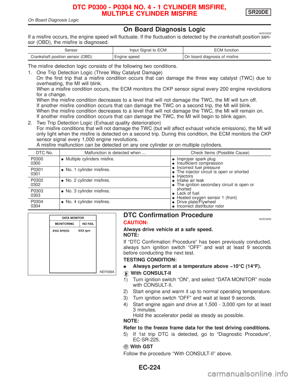
On Board Diagnosis LogicNCEC0202If a misfire occurs, the engine speed will fluctuate. If the fluctuation is detected by the crankshaft position sen-
sor (OBD), the misfire is diagnosed.
Sensor Input Signal to ECM ECM function
Crankshaft position sensor (OBD) Engine speed On board diagnosis of misfire
The misfire detection logic consists of the following two conditions.
1. One Trip Detection Logic (Three Way Catalyst Damage)
On the first trip that a misfire condition occurs that can damage the three way catalyst (TWC) due to
overheating, the MI will blink.
When a misfire condition occurs, the ECM monitors the CKP sensor signal every 200 engine revolutions
for a change.
When the misfire condition decreases to a level that will not damage the TWC, the MI will turn off.
If another misfire condition occurs that can damage the TWC on a second trip, the MI will blink.
When the misfire condition decreases to a level that will not damage the TWC, the MI will remain on.
If another misfire condition occurs that can damage the TWC, the MI will begin to blink again.
2. Two Trip Detection Logic (Exhaust quality deterioration)
For misfire conditions that will not damage the TWC (but will affect exhaust vehicle emissions), the MI will
only light when the misfire is detected on a second trip. During this condition, the ECM monitors the CKP
sensor signal every 1,000 engine revolutions.
A misfire malfunction can be detected on any one cylinder or on multiple cylinders.
DTC No. Malfunction is detected when ... Check Items (Possible Cause)
P0300
0300IMultiple cylinders misfire.IImproper spark plug
IInsufficient compression
IIncorrect fuel pressure
IThe injector circuit is open or shorted
IInjectors
IIntake air leak
IThe ignition secondary circuit is open or
shorted
ILack of fuel
IHeated oxygen sensor 1 (front)
IDrive plate/Flywheel
IIncorrect distributor rotor P0301
0301INo. 1 cylinder misfires.
P0302
0302INo. 2 cylinder misfires.
P0303
0303INo. 3 cylinder misfires.
P0304
0304INo. 4 cylinder misfires.
DTC Confirmation ProcedureNCEC0203CAUTION:
Always drive vehicle at a safe speed.
NOTE:
If ªDTC Confirmation Procedureº has been previously conducted,
always turn ignition switch ªOFFº and wait at least 9 seconds
before conducting the next test.
TESTING CONDITION:
IAlways perform at a temperature above þ10ÉC (14ÉF).
With CONSULT-II
1) Turn ignition switch ªONº, and select ªDATA MONITORº mode
with CONSULT-II.
2) Start engine and warm it up to normal operating temperature.
3) Turn ignition switch ªOFFº and wait at least 9 seconds.
4) Start engine again and drive at 1,500 - 3,000 rpm for at least
3 minutes.
Hold the accelerator pedal as steady as possible.
NOTE:
Refer to the freeze frame data for the test driving conditions.
5) If 1st trip DTC is detected, go to ªDiagnostic Procedureº,
EC-SR-225.
With GST
Follow the procedure ªWith CONSULT-IIº above.
NEF068A
DTC P0300 - P0304 NO.4-1CYLINDER MISFIRE,
MULTIPLE CYLINDER MISFIRESR20DE
On Board Diagnosis Logic
EC-224
Page 1034 of 2267
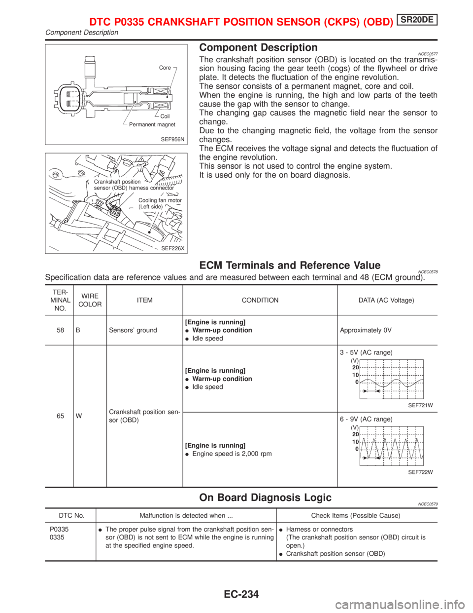
Component DescriptionNCEC0577The crankshaft position sensor (OBD) is located on the transmis-
sion housing facing the gear teeth (cogs) of the flywheel or drive
plate. It detects the fluctuation of the engine revolution.
The sensor consists of a permanent magnet, core and coil.
When the engine is running, the high and low parts of the teeth
cause the gap with the sensor to change.
The changing gap causes the magnetic field near the sensor to
change.
Due to the changing magnetic field, the voltage from the sensor
changes.
The ECM receives the voltage signal and detects the fluctuation of
the engine revolution.
This sensor is not used to control the engine system.
It is used only for the on board diagnosis.
ECM Terminals and Reference ValueNCEC0578Specification data are reference values and are measured between each terminal and 48 (ECM ground).
TER-
MINAL
NO.WIRE
COLORITEM CONDITION DATA (AC Voltage)
58 B Sensors' ground[Engine is running]
IWarm-up condition
IIdle speedApproximately 0V
65 WCrankshaft position sen-
sor (OBD)[Engine is running]
IWarm-up condition
IIdle speed3 - 5V (AC range)
SEF721W
[Engine is running]
IEngine speed is 2,000 rpm6 - 9V (AC range)
SEF722W
On Board Diagnosis LogicNCEC0579
DTC No. Malfunction is detected when ... Check Items (Possible Cause)
P0335
0335IThe proper pulse signal from the crankshaft position sen-
sor (OBD) is not sent to ECM while the engine is running
at the specified engine speed.IHarness or connectors
(The crankshaft position sensor (OBD) circuit is
open.)
ICrankshaft position sensor (OBD)
SEF956N Core
Permanent magnetCoil
SEF226X Crankshaft position
sensor (OBD) harness connector
Cooling fan motor
(Left side)
DTC P0335 CRANKSHAFT POSITION SENSOR (CKPS) (OBD)SR20DE
Component Description
EC-234