clutch NISSAN PRIMERA 1999 Electronic Repair Manual
[x] Cancel search | Manufacturer: NISSAN, Model Year: 1999, Model line: PRIMERA, Model: NISSAN PRIMERA 1999Pages: 2267, PDF Size: 35.74 MB
Page 1 of 2267
Edition:May 2001
GENERA LINFORMATIONGI
MAINTENANCEMA
ENGIN EMECHANICALEM
ENGIN ELUBRICATIO N&LC
ENGIN ECONTRO LSYSTEMQG16/18DE
ENGIN ECONTRO LSYSTEMSR20DE
ENGIN ECONTRO LSYSTEMCD20T
ACCELERATO RCONTROL,FE
CLUTCHCL
MANUA LTRANSAXLEMT
AUTOMATI CTRANSAXLEAT
FRON TAXL E& FRON TSUSPENSIONFA
REA RAXL E& REA RSUSPENSIONRA
BRAK ESYSTEMBR
STEERIN GSYSTEMST
RESTRAIN TSYSTEMRS
BOD Y& TRIMBT
HEATE R&AIR CONDITIONERHA
ELECTRICA LSYSTEMEL
ALPHABETICA LINDEXIDX
PRIMERA
NISSA NEUROP EN.V.
Page 3 of 2267
AUTOMATIC TRANSAXLE
SECTION
AT(H×CVT)
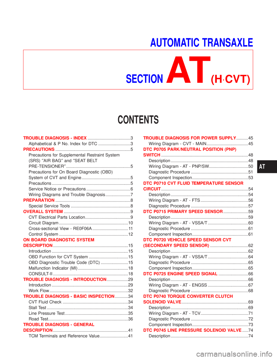
CONTENTS
TROUBLE DIAGNOSIS - INDEX....................................3
Alphabetical & P No. Index for DTC ...........................3
PRECAUTIONS...............................................................5
Precautions for Supplemental Restraint System
(SRS)²AIR BAG²and²SEAT BELT
PRE-TENSIONER²......................................................5
Precautions for On Board Diagnostic (OBD)
System of CVT and Engine .........................................5
Precautions ..................................................................5
Service Notice or Precautions .....................................6
Wiring Diagrams and Trouble Diagnosis .....................7
PREPARATION...............................................................8
Special Service Tools ..................................................8
OVERALL SYSTEM........................................................9
CVT Electrical Parts Location......................................9
Circuit Diagram ..........................................................10
Cross-sectional View - RE0F06A .............................. 11
Control System ..........................................................12
ON BOARD DIAGNOSTIC SYSTEM
DESCRIPTION...............................................................15
Introduction ................................................................15
OBD Function for CVT System .................................15
OBD Diagnostic Trouble Code (DTC) .......................15
Malfunction Indicator (MI) ..........................................18
CONSULT-II ...............................................................18
TROUBLE DIAGNOSIS - INTRODUCTION..................29
Introduction ................................................................29
Work Flow ..................................................................32
TROUBLE DIAGNOSIS - BASIC INSPECTION...........34
CVT Fluid Check .......................................................34
Stall Test ....................................................................34
Line Pressure Test .....................................................35
Road Test...................................................................36
TROUBLE DIAGNOSIS - GENERAL
DESCRIPTION...............................................................41
TCM Terminals and Reference Value........................41TROUBLE DIAGNOSIS FOR POWER SUPPLY..........45
Wiring Diagram - CVT - MAIN...................................45
DTC P0705 PARK/NEUTRAL POSITION (PNP)
SWITCH.........................................................................48
Description .................................................................48
Wiring Diagram - AT - PNP/SW.................................50
Diagnostic Procedure ................................................51
Component Inspection ...............................................53
DTC P0710 CVT FLUID TEMPERATURE SENSOR
CIRCUIT.........................................................................54
Description .................................................................54
Wiring Diagram - AT - FTS ........................................56
Diagnostic Procedure ................................................57
DTC P0715 PRIMARY SPEED SENSOR.....................59
Description .................................................................59
Wiring Diagram - AT - VSSA/T ..................................60
Diagnostic Procedure ................................................61
Component Inspection ...............................................61
DTC P0720 VEHICLE SPEED SENSOR CVT
(SECONDARY SPEED SENSOR)................................62
Description .................................................................62
Wiring Diagram - AT - VSSA/T ..................................64
Diagnostic Procedure ................................................65
Component Inspection ...............................................65
DTC P0725 ENGINE SPEED SIGNAL.........................66
Description .................................................................66
Wiring Diagram - AT - ENGSS ..................................67
Diagnostic Procedure ................................................68
DTC P0740 TORQUE CONVERTER CLUTCH
SOLENOID VALVE........................................................69
Description .................................................................69
Wiring Diagram - AT - TCV........................................71
Diagnostic Procedure ................................................72
Component Inspection ...............................................73
DTC P0745 LINE PRESSURE SOLENOID VALVE.....74
Description .................................................................74
AT
Page 13 of 2267

Cross-sectional View Ð RE0F06ANCAT0011
SAT668J Primary pulley
Steel belt
Sun gear
Side cover
Internal gear
Secondary pulley
Final gearDifferential caseSpeedometer drive gear Idler gear Reduction gear Taper roller bearingOutput gear Parking gear Input shaft Torque converter Converter housing
Oil pump
Forward clutch Reverse brake
Planet carrier
OVERALL SYSTEM
Cross-sectional View Ð RE0F06A
AT-11
Page 14 of 2267
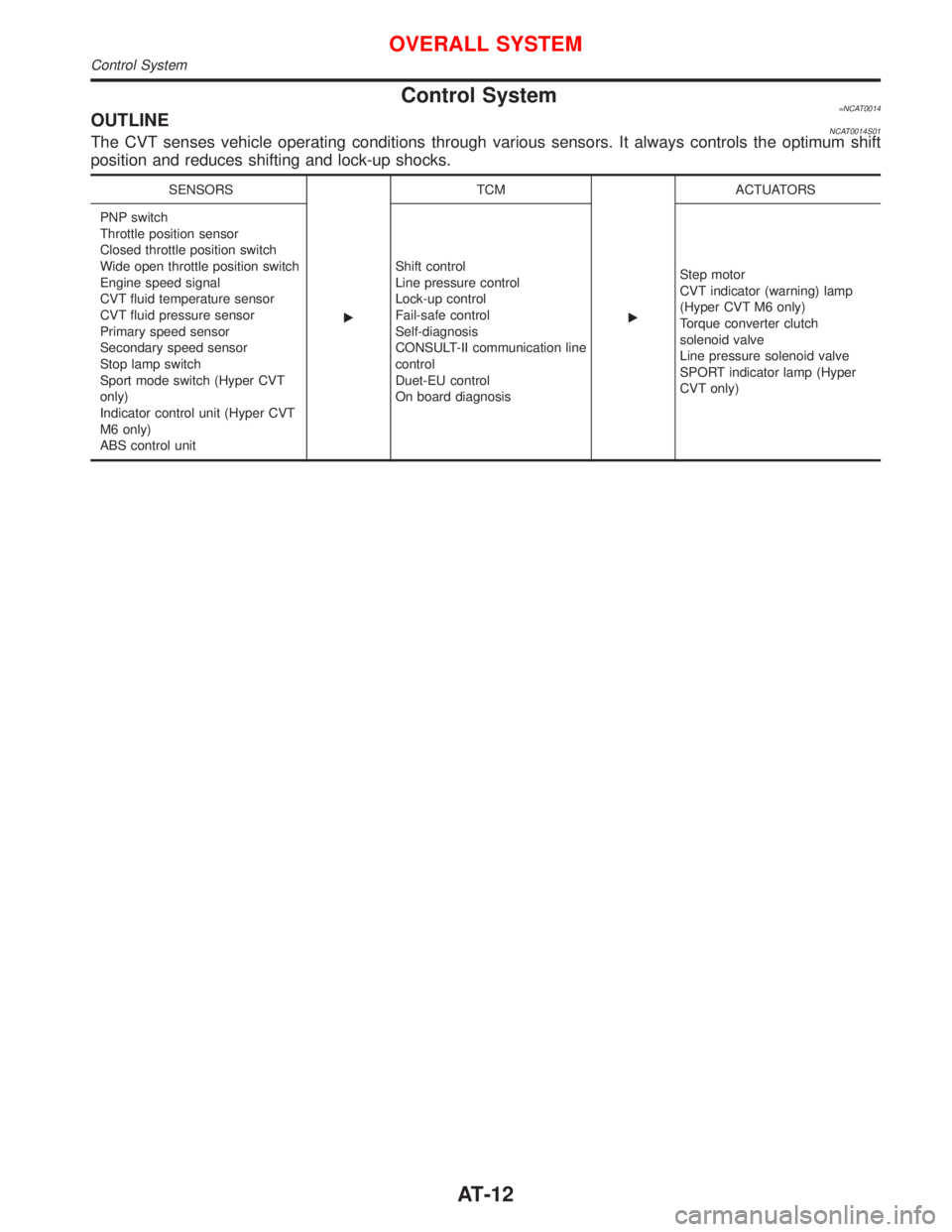
Control System=NCAT0014OUTLINENCAT0014S01The CVT senses vehicle operating conditions through various sensors. It always controls the optimum shift
position and reduces shifting and lock-up shocks.
SENSORS
ETCM
EACTUATORS
PNP switch
Throttle position sensor
Closed throttle position switch
Wide open throttle position switch
Engine speed signal
CVT fluid temperature sensor
CVT fluid pressure sensor
Primary speed sensor
Secondary speed sensor
Stop lamp switch
Sport mode switch (Hyper CVT
only)
Indicator control unit (Hyper CVT
M6 only)
ABS control unitShift control
Line pressure control
Lock-up control
Fail-safe control
Self-diagnosis
CONSULT-II communication line
control
Duet-EU control
On board diagnosisStep motor
CVT indicator (warning) lamp
(Hyper CVT M6 only)
Torque converter clutch
solenoid valve
Line pressure solenoid valve
SPORT indicator lamp (Hyper
CVT only)
OVERALL SYSTEM
Control System
AT-12
Page 16 of 2267
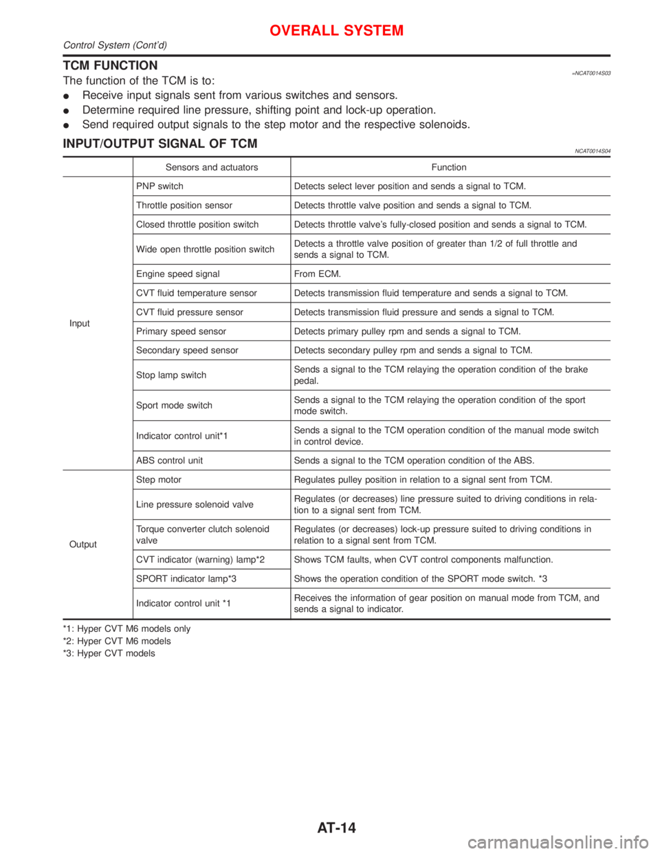
TCM FUNCTION=NCAT0014S03The function of the TCM is to:
IReceive input signals sent from various switches and sensors.
IDetermine required line pressure, shifting point and lock-up operation.
ISend required output signals to the step motor and the respective solenoids.
INPUT/OUTPUT SIGNAL OF TCMNCAT0014S04
Sensors and actuators Function
InputPNP switch Detects select lever position and sends a signal to TCM.
Throttle position sensor Detects throttle valve position and sends a signal to TCM.
Closed throttle position switch Detects throttle valve's fully-closed position and sends a signal to TCM.
Wide open throttle position switchDetects a throttle valve position of greater than 1/2 of full throttle and
sends a signal to TCM.
Engine speed signal From ECM.
CVT fluid temperature sensor Detects transmission fluid temperature and sends a signal to TCM.
CVT fluid pressure sensor Detects transmission fluid pressure and sends a signal to TCM.
Primary speed sensor Detects primary pulley rpm and sends a signal to TCM.
Secondary speed sensor Detects secondary pulley rpm and sends a signal to TCM.
Stop lamp switchSends a signal to the TCM relaying the operation condition of the brake
pedal.
Sport mode switchSends a signal to the TCM relaying the operation condition of the sport
mode switch.
Indicator control unit*1Sends a signal to the TCM operation condition of the manual mode switch
in control device.
ABS control unit Sends a signal to the TCM operation condition of the ABS.
OutputStep motor Regulates pulley position in relation to a signal sent from TCM.
Line pressure solenoid valveRegulates (or decreases) line pressure suited to driving conditions in rela-
tion to a signal sent from TCM.
Torque converter clutch solenoid
valveRegulates (or decreases) lock-up pressure suited to driving conditions in
relation to a signal sent from TCM.
CVT indicator (warning) lamp*2 Shows TCM faults, when CVT control components malfunction.
SPORT indicator lamp*3 Shows the operation condition of the SPORT mode switch. *3
Indicator control unit *1Receives the information of gear position on manual mode from TCM, and
sends a signal to indicator.
*1: Hyper CVT M6 models only
*2: Hyper CVT M6 models
*3: Hyper CVT models
OVERALL SYSTEM
Control System (Cont'd)
AT-14
Page 21 of 2267

SELF-DIAGNOSTIC PROCEDURE
(WITH CONSULT-II)
NCAT0022S021. Turn on CONSULT-II and touch ªENGINEº for OBD detected
items or touch ªCVTº for TCM self-diagnosis.
If CVT is not displayed, check TCM power supply and ground
circuit. Refer to AT-41. If result is NG, refer to EL section
(ªPOWER SUPPLY ROUTINGº).
2. Touch ªSELF DIAGNOSISº.
Display shows malfunction experienced since the last erasing
operation.
CONSULT-II performs REAL-TIME SELF-DIAGNOSIS.
Also, any malfunction detected while in this mode will be dis-
played at real time.
SELF-DIAGNOSTIC RESULT TEST MODENCAT0022S03
Detected items
(Screen terms for CONSULT-II, ªSELF
DIAGNOSISº test mode)
Malfunction is detected when ...TCM self-diagnosis OBD (DTC)
Available by
CVT or SPORT
indicator lamp
ªCVTº on CON-
SULT-IIAvailable by
malfunction
indicator lamp*2,
ªENGINEº on CON-
SULT-II or GST ªCVTº ªENGINEº
PNP switch circuitITCM does not receive the correct volt-
age signal (based on the gear posi-
tion) from the switch.Ð P0705
PNP SW/CIRCUITPNP SW/CIRC
Primary speed sensorITCM does not receive the proper volt-
age signal from the sensor.
X P0715
I/P PULLY SPD SIGPRI SPEED SIG/
CIRC
Secondary speed sensorITCM does not receive the proper volt-
age signal from the sensor.
X P0720
VEHICLE SPEED
SIGVEH SPD SEN/CIR
A/T
T/C clutch solenoid valveITCM detects an improper voltage drop
when it tries to operate the solenoid
valve.X P0740
T/C CLUTCH
SOL/VTCC SOLENOID/
CIRC
Line pressure solenoid valveITCM detects an improper voltage drop
when it tries to operate the solenoid
valve.X P0745
LINE PRESSURE
S/VL/PRESS SOL/
CIRC
Throttle position sensor,
Throttle position switchITCM receives an excessively low or
high voltage from the sensor.
X P1705
THROTTLE POSI
SENTP SEN/CIRC A/T
SAT651J
SAT584J
ON BOARD DIAGNOSTIC SYSTEM DESCRIPTION
CONSULT-II (Cont'd)
AT-19
Page 24 of 2267
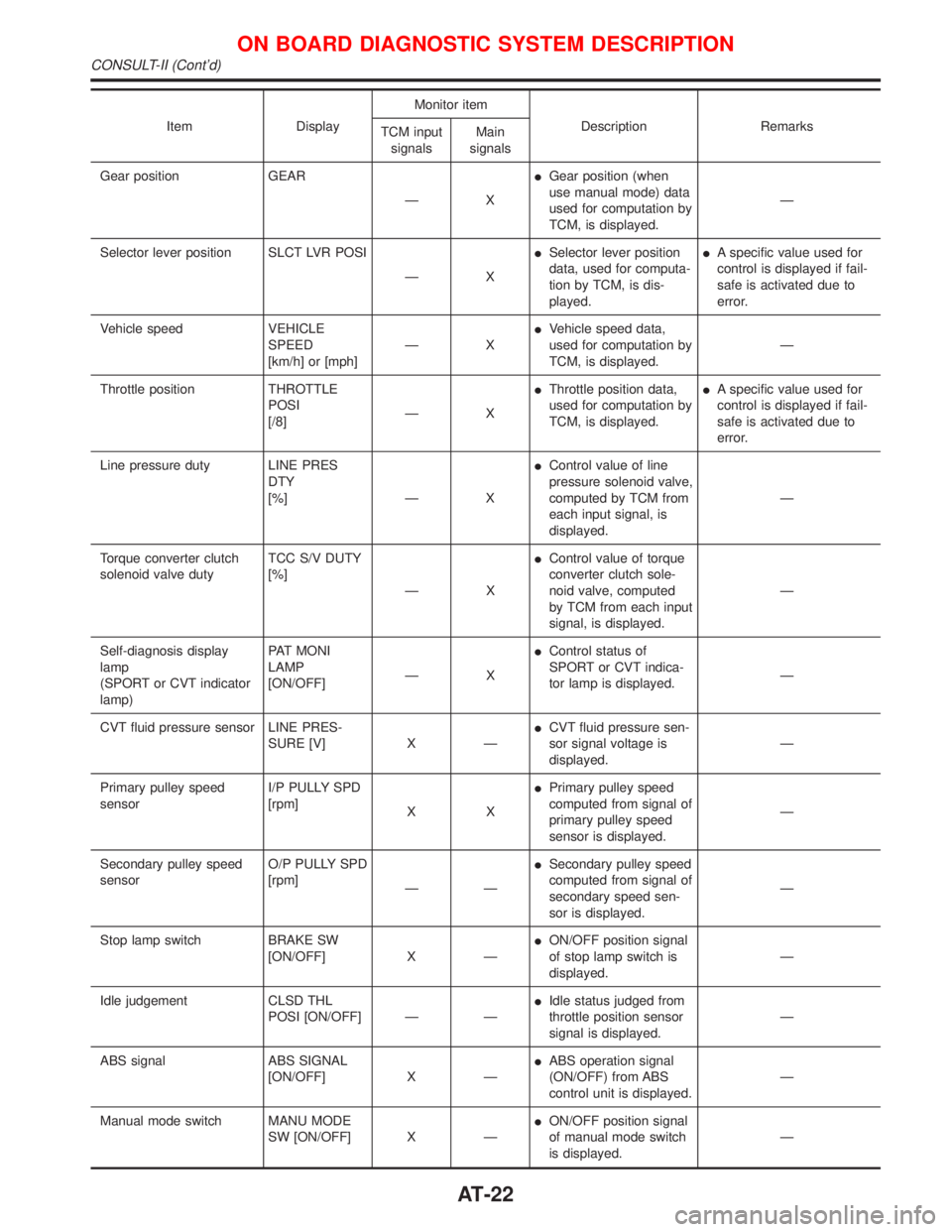
Item DisplayMonitor item
Description Remarks
TCM input
signalsMain
signals
Gear position GEAR
ÐXIGear position (when
use manual mode) data
used for computation by
TCM, is displayed.Ð
Selector lever position SLCT LVR POSI
ÐXISelector lever position
data, used for computa-
tion by TCM, is dis-
played.IA specific value used for
control is displayed if fail-
safe is activated due to
error.
Vehicle speed VEHICLE
SPEED
[km/h] or [mph]ÐXIVehicle speed data,
used for computation by
TCM, is displayed.Ð
Throttle position THROTTLE
POSI
[/8]ÐXIThrottle position data,
used for computation by
TCM, is displayed.IA specific value used for
control is displayed if fail-
safe is activated due to
error.
Line pressure duty LINE PRES
DTY
[%] Ð XIControl value of line
pressure solenoid valve,
computed by TCM from
each input signal, is
displayed.Ð
Torque converter clutch
solenoid valve dutyTCC S/V DUTY
[%]
ÐXIControl value of torque
converter clutch sole-
noid valve, computed
by TCM from each input
signal, is displayed.Ð
Self-diagnosis display
lamp
(SPORT or CVT indicator
lamp)PAT MONI
LAMP
[ON/OFF]ÐXIControl status of
SPORT or CVT indica-
tor lamp is displayed.Ð
CVT fluid pressure sensor LINE PRES-
SURE [V] X ÐICVT fluid pressure sen-
sor signal voltage is
displayed.Ð
Primary pulley speed
sensorI/P PULLY SPD
[rpm]
XXIPrimary pulley speed
computed from signal of
primary pulley speed
sensor is displayed.Ð
Secondary pulley speed
sensorO/P PULLY SPD
[rpm]
ÐÐISecondary pulley speed
computed from signal of
secondary speed sen-
sor is displayed.Ð
Stop lamp switch BRAKE SW
[ON/OFF] X ÐION/OFF position signal
of stop lamp switch is
displayed.Ð
Idle judgement CLSD THL
POSI [ON/OFF] Ð ÐIIdle status judged from
throttle position sensor
signal is displayed.Ð
ABS signal ABS SIGNAL
[ON/OFF] X ÐIABS operation signal
(ON/OFF) from ABS
control unit is displayed.Ð
Manual mode switch MANU MODE
SW [ON/OFF] X ÐION/OFF position signal
of manual mode switch
is displayed.Ð
ON BOARD DIAGNOSTIC SYSTEM DESCRIPTION
CONSULT-II (Cont'd)
AT-22
Page 29 of 2267
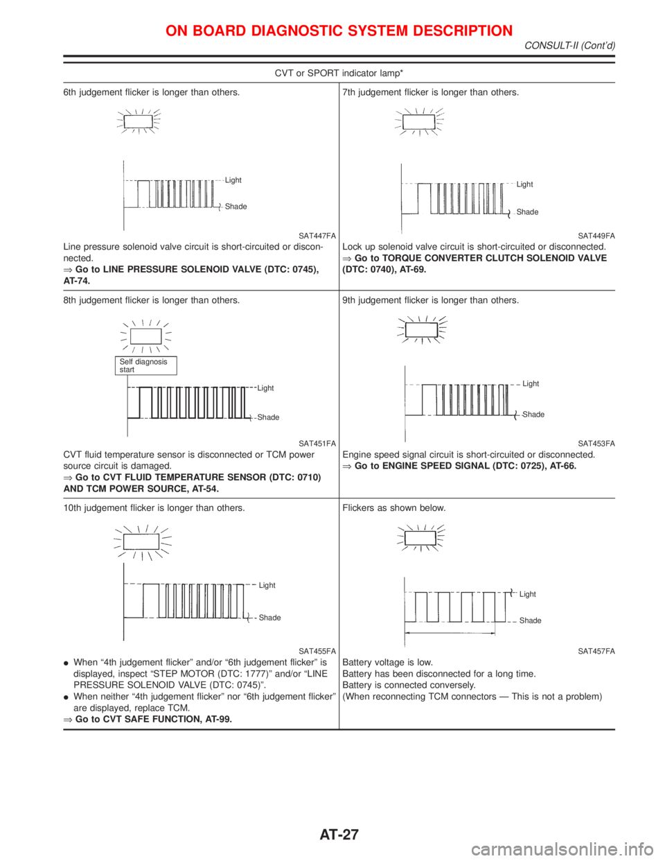
CVT or SPORT indicator lamp*
6th judgement flicker is longer than others.
SAT447FA
Line pressure solenoid valve circuit is short-circuited or discon-
nected.
ÞGo to LINE PRESSURE SOLENOID VALVE (DTC: 0745),
AT-74.
Light
Shade
7th judgement flicker is longer than others.
SAT449FA
Lock up solenoid valve circuit is short-circuited or disconnected.
ÞGo to TORQUE CONVERTER CLUTCH SOLENOID VALVE
(DTC: 0740), AT-69.
Light
Shade
8th judgement flicker is longer than others.
SAT451FA
CVT fluid temperature sensor is disconnected or TCM power
source circuit is damaged.
ÞGo to CVT FLUID TEMPERATURE SENSOR (DTC: 0710)
AND TCM POWER SOURCE, AT-54.
Self diagnosis
start
Light
Shade
9th judgement flicker is longer than others.
SAT453FA
Engine speed signal circuit is short-circuited or disconnected.
ÞGo to ENGINE SPEED SIGNAL (DTC: 0725), AT-66.
Light
Shade
10th judgement flicker is longer than others.
SAT455FA Light
Shade
IWhen ª4th judgement flickerº and/or ª6th judgement flickerº is
displayed, inspect ªSTEP MOTOR (DTC: 1777)º and/or ªLINE
PRESSURE SOLENOID VALVE (DTC: 0745)º.
IWhen neither ª4th judgement flickerº nor ª6th judgement flickerº
are displayed, replace TCM.
ÞGo to CVT SAFE FUNCTION, AT-99.Flickers as shown below.
SAT457FA
Battery voltage is low.
Battery has been disconnected for a long time.
Battery is connected conversely.
(When reconnecting TCM connectors Ð This is not a problem)
Light
Shade
ON BOARD DIAGNOSTIC SYSTEM DESCRIPTION
CONSULT-II (Cont'd)
AT-27
Page 33 of 2267
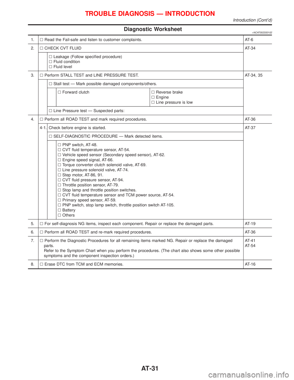
Diagnostic Worksheet=NCAT0023S0102
1.lRead the Fail-safe and listen to customer complaints. AT-6
2.lCHECK CVT FLUIDAT-34
lLeakage (Follow specified procedure)
lFluid condition
lFluid level
3.lPerform STALL TEST and LINE PRESSURE TEST. AT-34, 35
lStall test Ð Mark possible damaged components/others.
lForward clutchlReverse brake
lEngine
lLine pressure is low
lLine Pressure test Ð Suspected parts:
4.lPerform all ROAD TEST and mark required procedures. AT-36
4-1. Check before engine is started.AT-37
lSELF-DIAGNOSTIC PROCEDURE Ð Mark detected items.
lPNP switch, AT-48.
lCVT fluid temperature sensor, AT-54.
lVehicle speed sensor (Secondary speed sensor), AT-62.
lEngine speed signal, AT-66.
lTorque converter clutch solenoid valve, AT-69.
lLine pressure solenoid valve, AT-74.
lStep motor, AT-86, 91.
lCVT fluid pressure sensor, AT-94.
lThrottle position sensor, AT-79.
lStop lamp and throttle position switches.
lCVT fluid temperature sensor and TCM power source, AT-54.
lPrimary speed sensor, AT-59.
lPNP switch, stop lamp switch, throttle position switch AT-105.
lBattery
lOthers
5.lFor self-diagnosis NG items, inspect each component. Repair or replace the damaged parts. AT-19
6.lPerform all ROAD TEST and re-mark required procedures. AT-36
7.lPerform the Diagnostic Procedures for all remaining items marked NG. Repair or replace the damaged
parts.
Refer to the Symptom Chart when you perform the procedures. (The chart also shows some other possible
symptoms and the component inspection orders.)AT-41
AT-54
8.lErase DTC from TCM and ECM memories. AT-16
TROUBLE DIAGNOSIS Ð INTRODUCTION
Introduction (Cont'd)
AT-31
Page 43 of 2267
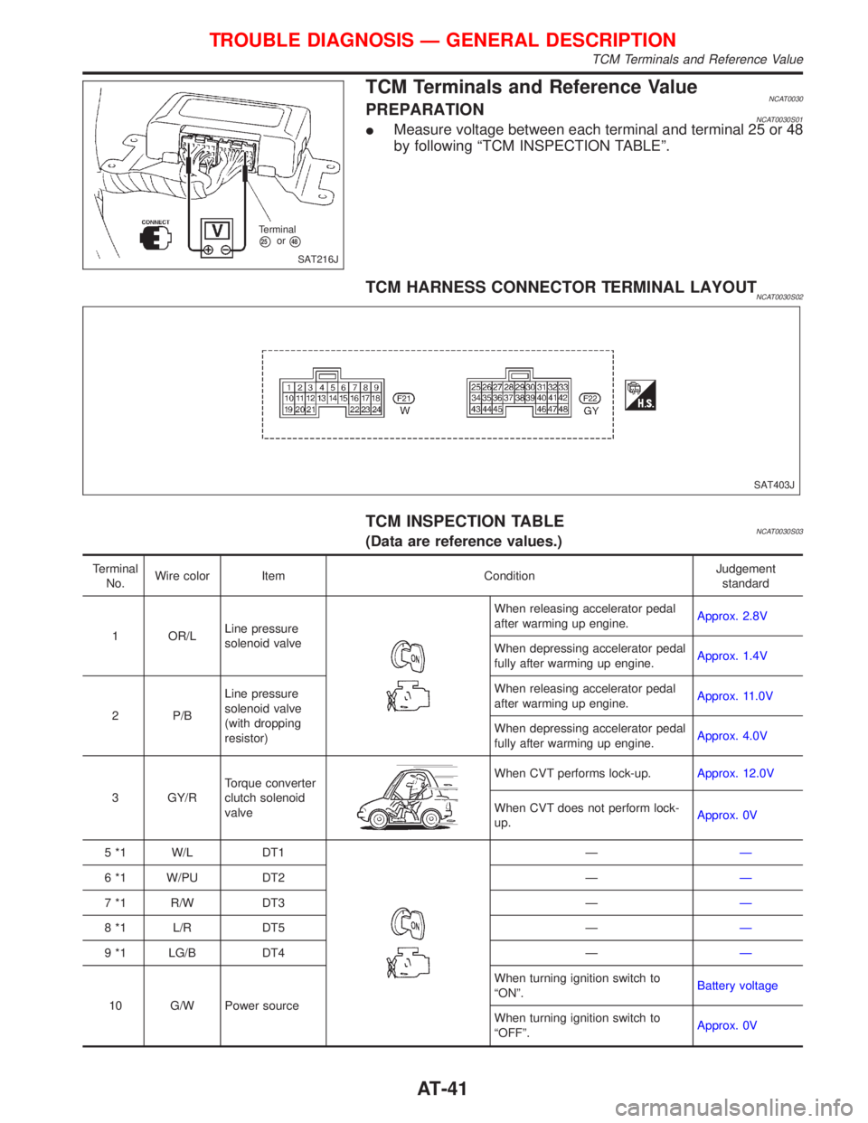
TCM Terminals and Reference ValueNCAT0030PREPARATIONNCAT0030S01IMeasure voltage between each terminal and terminal 25 or 48
by following ªTCM INSPECTION TABLEº.
TCM HARNESS CONNECTOR TERMINAL LAYOUTNCAT0030S02
TCM INSPECTION TABLENCAT0030S03(Data are reference values.)
Terminal
No.Wire color Item ConditionJudgement
standard
1 OR/LLine pressure
solenoid valve
When releasing accelerator pedal
after warming up engine.Approx. 2.8V
When depressing accelerator pedal
fully after warming up engine.Approx. 1.4V
2 P/BLine pressure
solenoid valve
(with dropping
resistor)When releasing accelerator pedal
after warming up engine.Approx. 11.0V
When depressing accelerator pedal
fully after warming up engine.Approx. 4.0V
3 GY/RTorque converter
clutch solenoid
valve
When CVT performs lock-up.Approx. 12.0V
When CVT does not perform lock-
up.Approx. 0V
5 *1 W/L DT1
ÐÐ
6 *1 W/PU DT2 ÐÐ
7 *1 R/W DT3 ÐÐ
8 *1 L/R DT5 ÐÐ
9 *1 LG/B DT4 ÐÐ
10 G/W Power sourceWhen turning ignition switch to
ªONº.Battery voltage
When turning ignition switch to
ªOFFº.Approx. 0V
SAT216J Terminal
p25orp48
SAT403J
TROUBLE DIAGNOSIS Ð GENERAL DESCRIPTION
TCM Terminals and Reference Value
AT-41