servo NISSAN PRIMERA 1999 Electronic Repair Manual
[x] Cancel search | Manufacturer: NISSAN, Model Year: 1999, Model line: PRIMERA, Model: NISSAN PRIMERA 1999Pages: 2267, PDF Size: 35.74 MB
Page 129 of 2267
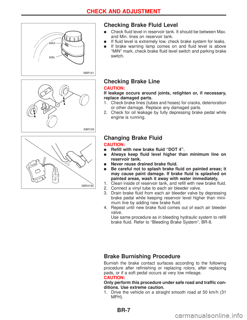
Checking Brake Fluid Level
lCheck fluid level in reservoir tank. It should be between Max.
and Min. lines on reservoir tank.
lIf fluid level is extremely low, check brake system for leaks.
lIf brake warning lamp comes on and fluid level is above
ªMINº mark, check brake fluid level switch and parking brake
switch.
Checking Brake Line
CAUTION:
If leakage occurs around joints, retighten or, if necessary,
replace damaged parts.
1. Check brake lines (tubes and hoses) for cracks, deterioration
or other damage. Replace any damaged parts.
2. Check for oil leakage by fully depressing brake pedal while
engine is running.
Changing Brake Fluid
CAUTION:
lRefill with new brake fluid ªDOT 4º.
lAlways keep fluid level higher than minimum line on
reservoir tank.
lNever reuse drained brake fluid.
lBe careful not to splash brake fluid on painted areas; it
may cause paint damage. If brake fluid is splashed on
painted areas, wash it away with water immediately.
1. Clean inside of reservoir tank, and refill with new brake fluid.
2. Connect a vinyl tube to each air bleeder valve.
3. Drain brake fluid from each air bleeder valve by depressing
brake pedal while keeping reservoir level higher than mini-
mum line by adding new brake fluid.
4. Repeat until new brake fluid comes out of each air bleeder
valve.
Use same procedure as in bleeding hydraulic system to refill
brake fluid. Refer to ªBleeding Brake Systemº, BR-8.
Brake Burnishing Procedure
Burnish the brake contact surfaces according to the following
procedure after refinishing or replacing rotors, after replacing
pads, or if a soft pedal occurs at very low mileage.
CAUTION:
Only perform this procedure under safe road and traffic con-
ditions. Use extreme caution.
1. Drive the vehicle on a straight smooth road at 50 km/h (31
MPH).
NBR141 MAX.
MIN.
ABR159
SBR419C
CHECK AND ADJUSTMENT
BR-7
Page 130 of 2267
2. Use medium brake pedal/foot effort to bring the vehicle to a
complete stop from 50 km/h (31 MPH). Adjust brake pedal/
foot pressure such that vehicle stopping time equals 3 to 5
seconds.
3. To cool the brake system, drive the vehicle at 50 km/h (31
MPH) for 1 minute without stopping.
4. Repeat steps 1 to 3, 10 times or more to complete the bur-
nishing procedure.
Bleeding Brake System
CAUTION:
lCarefully monitor brake fluid level at master cylinder
during bleeding operation.
lIf master cylinder is suspected to have air inside, bleed
air from master cylinder first. Refer to ªInstallationº,
ªMASTER CYLINDERº, BR-17.
lFill reservoir with new brake fluid ªDOT 4º. Make sure it
is full at all times while bleeding air out of system.
lPlace a container under master cylinder to avoid spillage
of brake fluid.
lFor models with ABS, turn ignition switch to the OFF
position and disconnect ABS fuse or battery cable.
lBleed air in the following order:
RHD models
Left rear brake,Right front brake,Right rear brake,Left
front brake
LHD models
Right rear brake,Left front brake,Left rear brake,Right
front brake.
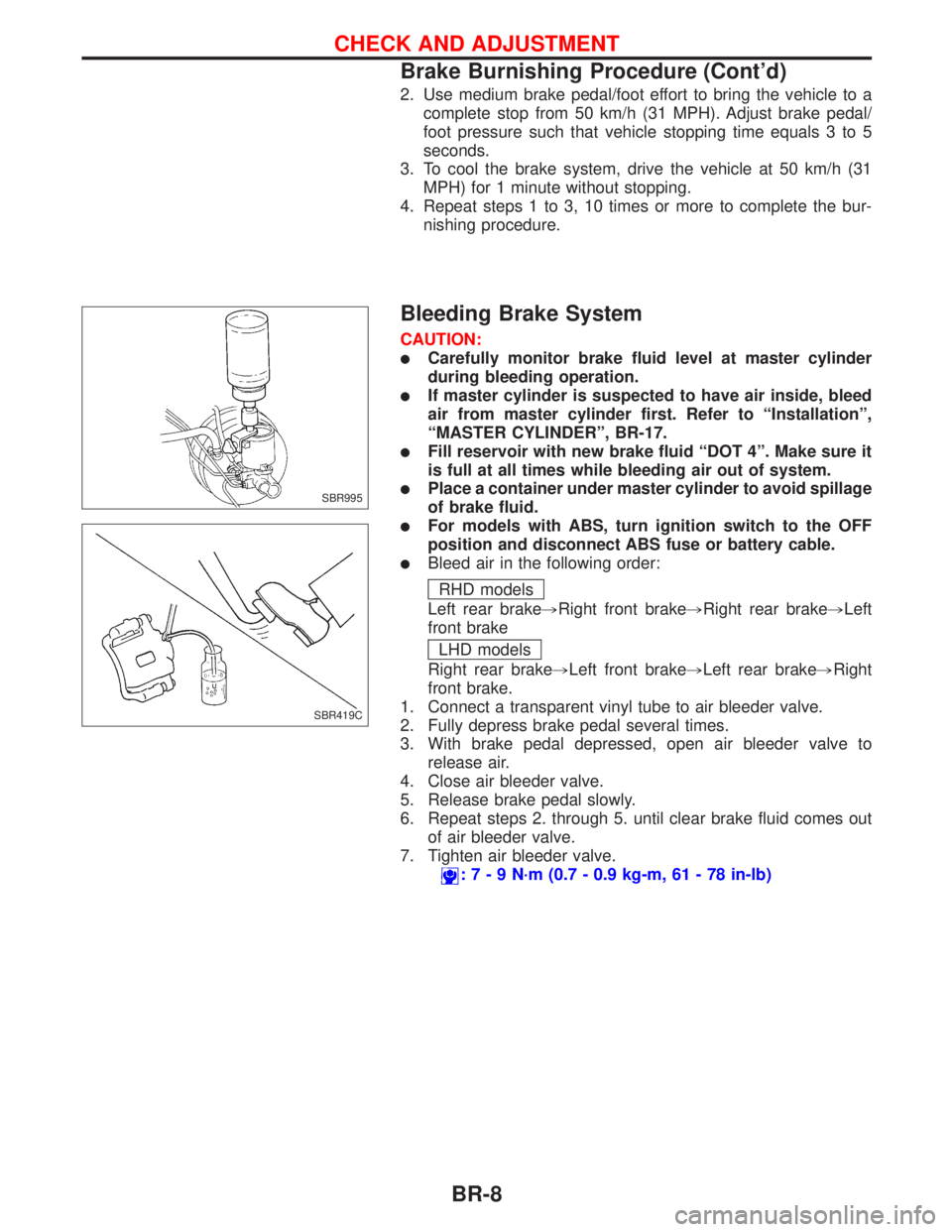
1. Connect a transparent vinyl tube to air bleeder valve.
2. Fully depress brake pedal several times.
3. With brake pedal depressed, open air bleeder valve to
release air.
4. Close air bleeder valve.
5. Release brake pedal slowly.
6. Repeat steps 2. through 5. until clear brake fluid comes out
of air bleeder valve.
7. Tighten air bleeder valve.
:7-9N´m(0.7 - 0.9 kg-m, 61 - 78 in-lb)
SBR995
SBR419C
CHECK AND ADJUSTMENT
Brake Burnishing Procedure (Cont'd)
BR-8
Page 137 of 2267
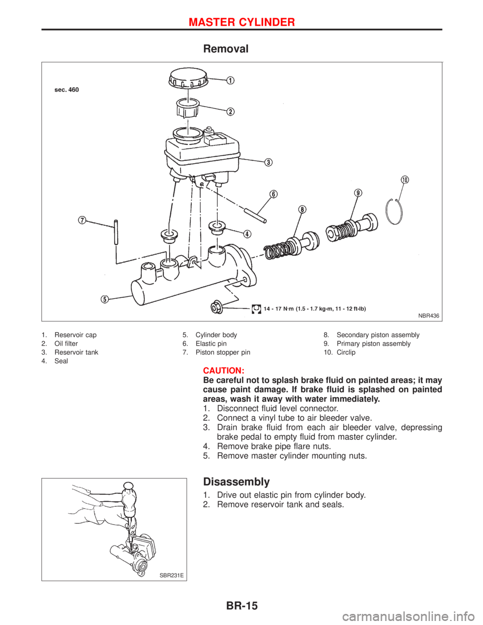
Removal
1. Reservoir cap
2. Oil filter
3. Reservoir tank
4. Seal5. Cylinder body
6. Elastic pin
7. Piston stopper pin8. Secondary piston assembly
9. Primary piston assembly
10. Circlip
CAUTION:
Be careful not to splash brake fluid on painted areas; it may
cause paint damage. If brake fluid is splashed on painted
areas, wash it away with water immediately.
1. Disconnect fluid level connector.
2. Connect a vinyl tube to air bleeder valve.
3. Drain brake fluid from each air bleeder valve, depressing
brake pedal to empty fluid from master cylinder.
4. Remove brake pipe flare nuts.
5. Remove master cylinder mounting nuts.
Disassembly
1. Drive out elastic pin from cylinder body.
2. Remove reservoir tank and seals.
NBR436
SBR231E
MASTER CYLINDER
BR-15
Page 138 of 2267
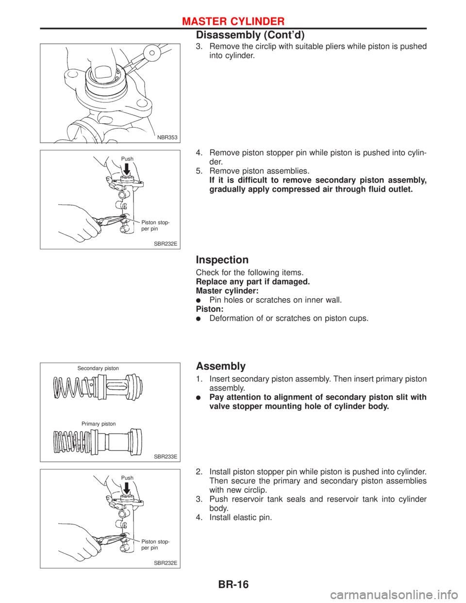
3. Remove the circlip with suitable pliers while piston is pushed
into cylinder.
4. Remove piston stopper pin while piston is pushed into cylin-
der.
5. Remove piston assemblies.
If it is difficult to remove secondary piston assembly,
gradually apply compressed air through fluid outlet.
Inspection
Check for the following items.
Replace any part if damaged.
Master cylinder:
lPin holes or scratches on inner wall.
Piston:
lDeformation of or scratches on piston cups.
Assembly
1. Insert secondary piston assembly. Then insert primary piston
assembly.
lPay attention to alignment of secondary piston slit with
valve stopper mounting hole of cylinder body.
2. Install piston stopper pin while piston is pushed into cylinder.
Then secure the primary and secondary piston assemblies
with new circlip.
3. Push reservoir tank seals and reservoir tank into cylinder
body.
4. Install elastic pin.
NBR353
Push
Piston stop-
per pin
SBR232E
Secondary piston
Primary piston
SBR233E
Push
Piston stop-
per pin
SBR232E
MASTER CYLINDER
Disassembly (Cont'd)
BR-16
Page 139 of 2267
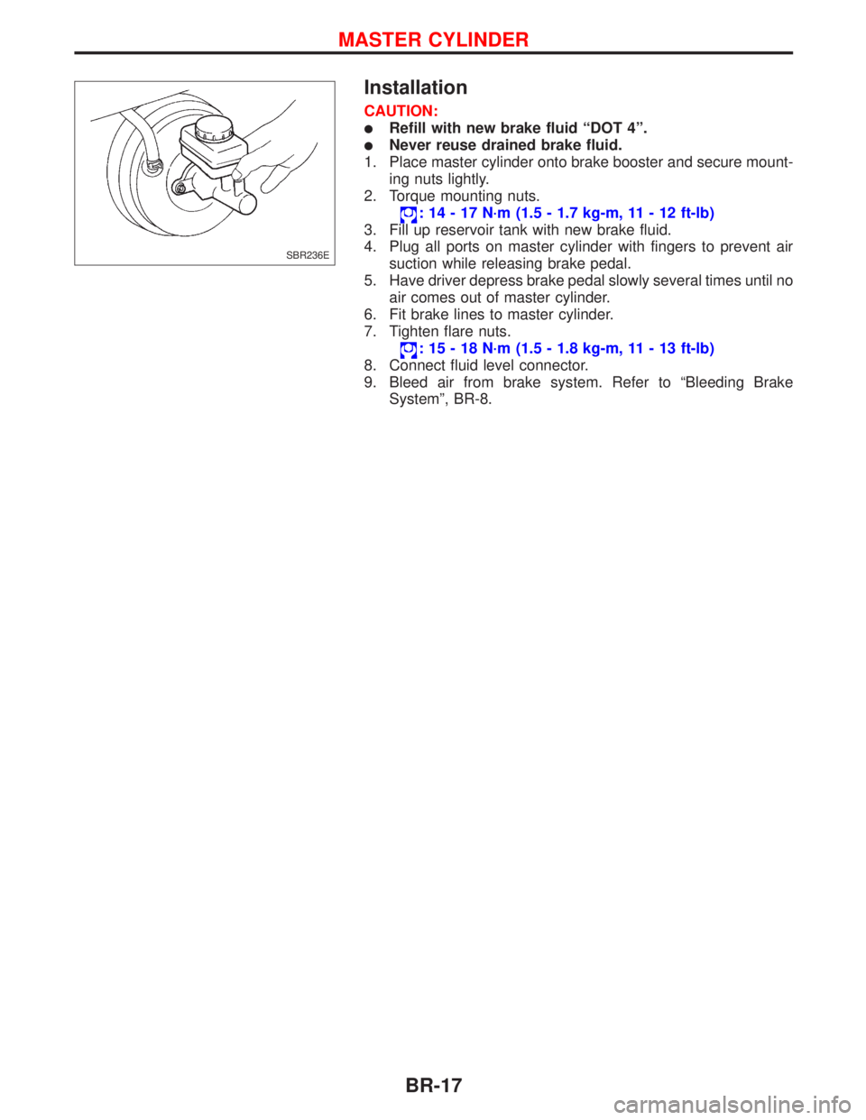
Installation
CAUTION:
lRefill with new brake fluid ªDOT 4º.
lNever reuse drained brake fluid.
1. Place master cylinder onto brake booster and secure mount-
ing nuts lightly.
2. Torque mounting nuts.
: 14 - 17 N´m (1.5 - 1.7 kg-m, 11 - 12 ft-lb)
3. Fill up reservoir tank with new brake fluid.
4. Plug all ports on master cylinder with fingers to prevent air
suction while releasing brake pedal.
5. Have driver depress brake pedal slowly several times until no
air comes out of master cylinder.
6. Fit brake lines to master cylinder.
7. Tighten flare nuts.
: 15 - 18 N´m (1.5 - 1.8 kg-m, 11 - 13 ft-lb)
8. Connect fluid level connector.
9. Bleed air from brake system. Refer to ªBleeding Brake
Systemº, BR-8.
SBR236E
MASTER CYLINDER
BR-17
Page 142 of 2267
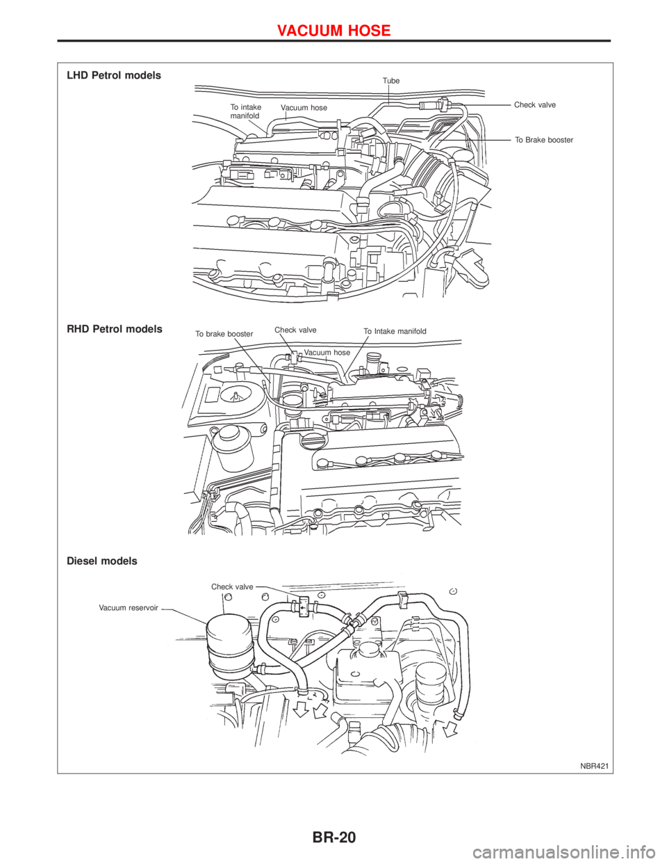
NBR421
Diesel models
Tube
Check valve
To Intake manifold
Check valveCheck valve
Vacuum reservoirLHD Petrol models
RHD Petrol models
To Brake booster Vacuum hose To intake
manifold
.Vacuum hose To brake booster
VACUUM HOSE
BR-20
Page 146 of 2267
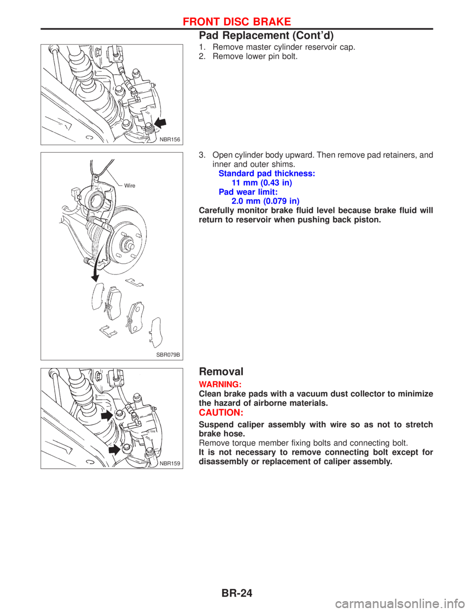
1. Remove master cylinder reservoir cap.
2. Remove lower pin bolt.
3. Open cylinder body upward. Then remove pad retainers, and
inner and outer shims.
Standard pad thickness:
11 mm (0.43 in)
Pad wear limit:
2.0 mm (0.079 in)
Carefully monitor brake fluid level because brake fluid will
return to reservoir when pushing back piston.
Removal
WARNING:
Clean brake pads with a vacuum dust collector to minimize
the hazard of airborne materials.
CAUTION:
Suspend caliper assembly with wire so as not to stretch
brake hose.
Remove torque member fixing bolts and connecting bolt.
It is not necessary to remove connecting bolt except for
disassembly or replacement of caliper assembly.
NBR156
SBR079B Wire
NBR159
FRONT DISC BRAKE
Pad Replacement (Cont'd)
BR-24
Page 150 of 2267
CAUTION:
Do not use any sharp tools or cleaning agents which con-
tains mineral oil. Damage to the installation can occur.
10. Clean the cylinder body and guide grooves in the torque
member.
11. Check the dust cover and guide sleeves for damage.
12. Measure the amount of wear on the brake pad
Standard pad thickness:
11 mm (0.43 in)
Pad wear limit:
2.0 mm (0.079 in)
14. Press the piston fully back with a suitable tool.
CAUTION:
Carefully monitor brake fluid level to avoid brake fluid from
returning to the reservoir when pushing back the piston.
Installation
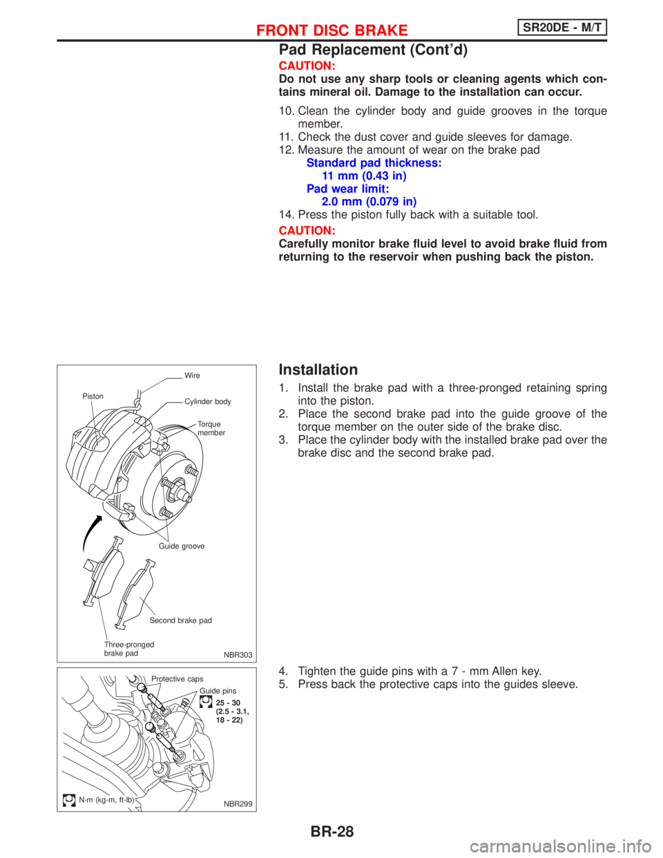
1. Install the brake pad with a three-pronged retaining spring
into the piston.
2. Place the second brake pad into the guide groove of the
torque member on the outer side of the brake disc.
3. Place the cylinder body with the installed brake pad over the
brake disc and the second brake pad.
4. Tighten the guide pins witha7-mmAllen key.
5. Press back the protective caps into the guides sleeve.
NBR303
Wire
Cylinder body
Torque
member
Guide groove
Second brake pad
Three-pronged
brake pad Piston
Guide pins
25-30
(2.5 - 3.1,
18 - 22) Protective caps
.N´m (kg-m, ft-lb)NBR299
FRONT DISC BRAKESR20DE - M/T
Pad Replacement (Cont'd)
BR-28
Page 156 of 2267
lIt is not necessary to remove connecting bolt except for
disassembly or replacement of caliper assembly. In this
case, suspend cylinder body with wire so as not to
stretch brake hose.
lBurnish the brake contact surfaces after refinishing or
replacing rotors, after replacing pads, or if a soft pedal
occurs at very low mileage.
Refer to ªBrake Burnishing Procedureº, ªCHECK AND
ADJUSTMENTº, BR-7.
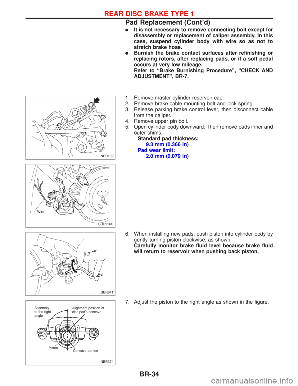
1. Remove master cylinder reservoir cap.
2. Remove brake cable mounting bolt and lock spring.
3. Release parking brake control lever, then disconnect cable
from the caliper.
4. Remove upper pin bolt.
5. Open cylinder body downward. Then remove pads inner and
outer shims.
Standard pad thickness:
9.3 mm (0.366 in)
Pad wear limit:
2.0 mm (0.079 in)
6. When installing new pads, push piston into cylinder body by
gently turning piston clockwise, as shown.
Carefully monitor brake fluid level because brake fluid
will return to reservoir when pushing back piston.
7. Adjust the piston to the right angle as shown in the figure.
NBR192
SBR916C Wire
SBR641
NBR374 Alignment position of
disc pad's concave
Concave portion Piston Assembly
to the right
angle
REAR DISC BRAKE TYPE 1
Pad Replacement (Cont'd)
BR-34
Page 157 of 2267
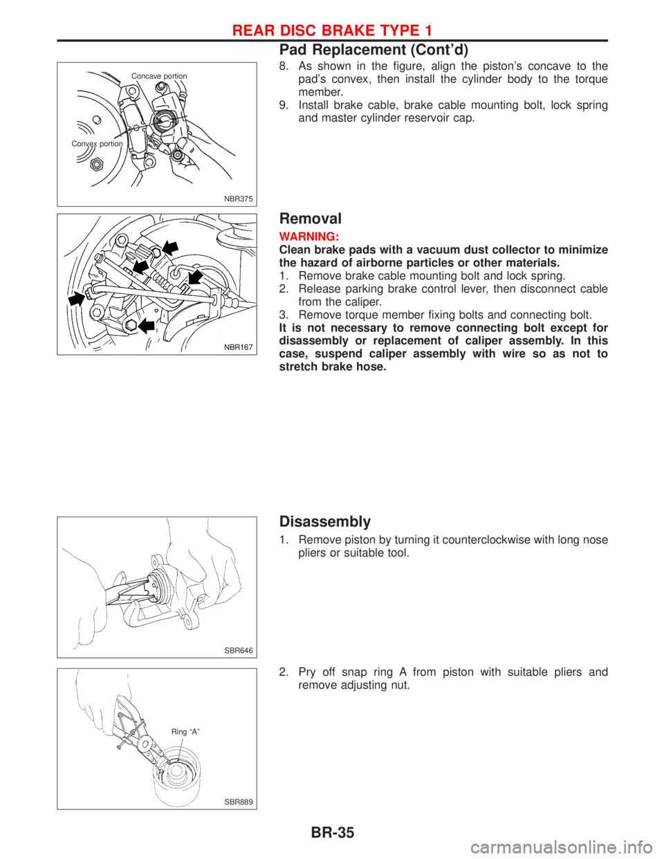
8. As shown in the figure, align the piston's concave to the
pad's convex, then install the cylinder body to the torque
member.
9. Install brake cable, brake cable mounting bolt, lock spring
and master cylinder reservoir cap.
Removal
WARNING:
Clean brake pads with a vacuum dust collector to minimize
the hazard of airborne particles or other materials.
1. Remove brake cable mounting bolt and lock spring.
2. Release parking brake control lever, then disconnect cable
from the caliper.
3. Remove torque member fixing bolts and connecting bolt.
It is not necessary to remove connecting bolt except for
disassembly or replacement of caliper assembly. In this
case, suspend caliper assembly with wire so as not to
stretch brake hose.
Disassembly
1. Remove piston by turning it counterclockwise with long nose
pliers or suitable tool.
2. Pry off snap ring A from piston with suitable pliers and
remove adjusting nut.
NBR375 Concave portion
Convex portion
NBR167
SBR646
SBR889 Ring ªAº
REAR DISC BRAKE TYPE 1
Pad Replacement (Cont'd)
BR-35