tire size NISSAN PRIMERA 1999 Electronic Repair Manual
[x] Cancel search | Manufacturer: NISSAN, Model Year: 1999, Model line: PRIMERA, Model: NISSAN PRIMERA 1999Pages: 2267, PDF Size: 35.74 MB
Page 1745 of 2267
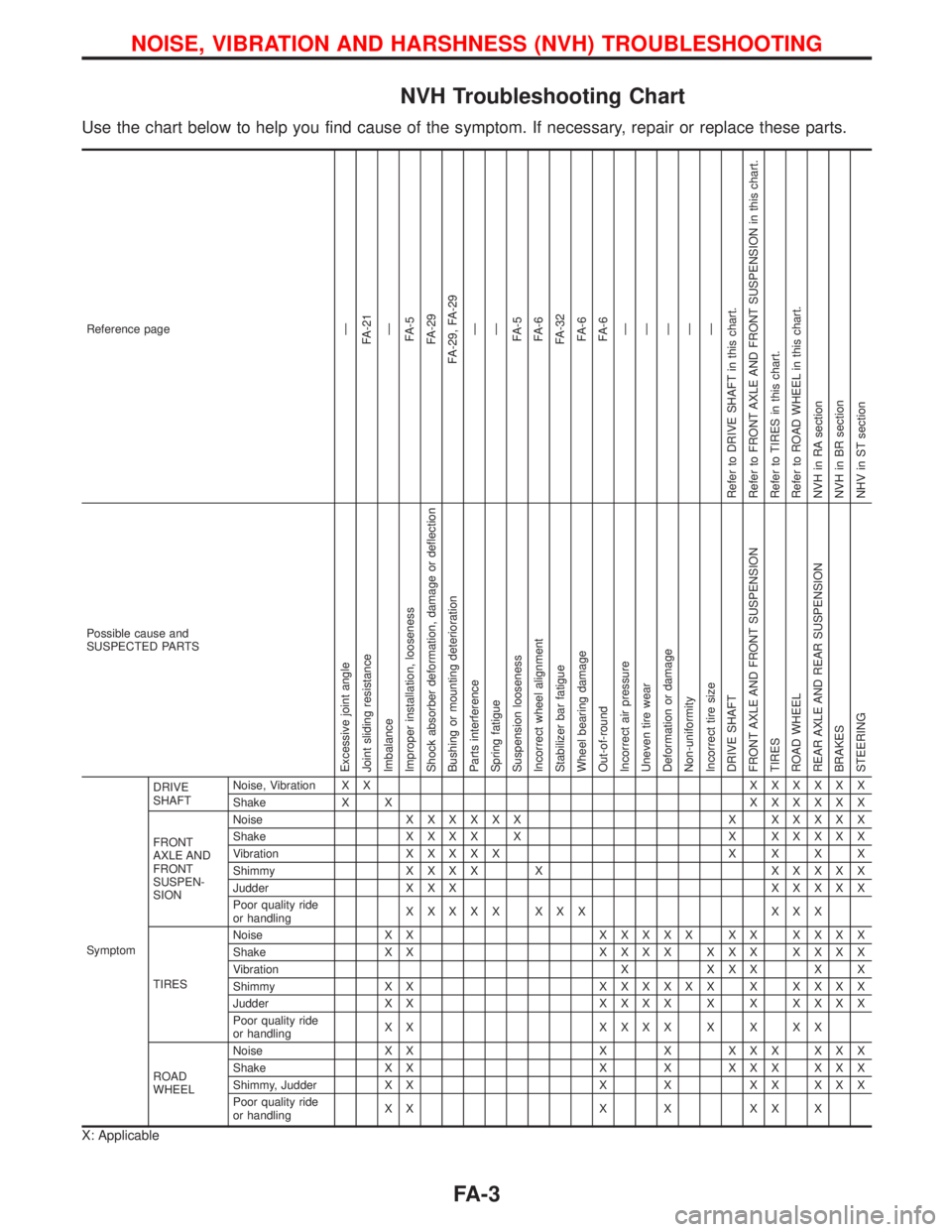
NVH Troubleshooting Chart
Use the chart below to help you find cause of the symptom. If necessary, repair or replace these parts.
Reference pageÐ
FA-21
Ð
FA-5
FA-29
FA-29, FA-29
Ð
Ð
FA-5
FA-6
FA-32
FA-6
FA-6
Ð
Ð
Ð
Ð
Ð
Refer to DRIVE SHAFT in this chart.
Refer to FRONT AXLE AND FRONT SUSPENSION in this chart.
Refer to TIRES in this chart.
Refer to ROAD WHEEL in this chart.
NVH in RA section
NVH in BR section
NHV in ST section
Possible cause and
SUSPECTED PARTS
Excessive joint angle
Joint sliding resistance
Imbalance
Improper installation, looseness
Shock absorber deformation, damage or deflection
Bushing or mounting deterioration
Parts interference
Spring fatigue
Suspension looseness
Incorrect wheel alignment
Stabilizer bar fatigue
Wheel bearing damage
Out-of-round
Incorrect air pressure
Uneven tire wear
Deformation or damage
Non-uniformity
Incorrect tire size
DRIVE SHAFT
FRONT AXLE AND FRONT SUSPENSION
TIRES
ROAD WHEEL
REAR AXLE AND REAR SUSPENSION
BRAKES
STEERING
SymptomDRIVE
SHAFTNoise, Vibration X XXXXXXX
Shake X XXXXXXX
FRONT
AXLE AND
FRONT
SUSPEN-
SIONNoiseXXXXXX X XXXXX
ShakeXXXX X X XXXXX
VibrationXXXXXXXXX
ShimmyXXXX X XXXXX
Judder X X XXXXXX
Poor quality ride
or handlingXXXXX XXX XXX
TIRESNoise X XXXXXX XX XXXX
Shake X XXXXX XXX XXXX
Vibration X X X X X X
Shimmy X XXXXXXX X XXXX
Judder X XXXXX X X XXXX
Poor quality ride
or handlingXX XXXXXXXX
ROAD
WHEELNoise X X X X X X X X X X
Shake X X X X X X X X X X
Shimmy, Judder X X X X X X X X X
Poor quality ride
or handlingXX X X XX X
X: Applicable
NOISE, VIBRATION AND HARSHNESS (NVH) TROUBLESHOOTING
FA-3
Page 1840 of 2267
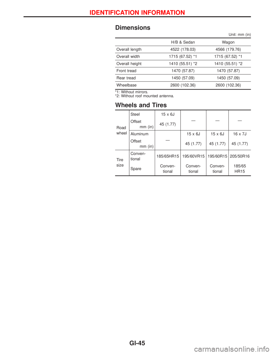
Dimensions
Unit: mm (in)
H/B & Sedan Wagon
Overall length 4522 (178.03) 4566 (179.76)
Overall width 1715 (67.52) *1 1715 (67.52) *1
Overall height 1410 (55.51) *2 1410 (55.51) *2
Front tread 1470 (57.87) 1470 (57.87)
Rear tread 1450 (57.09) 1450 (57.09)
Wheelbase 2600 (102.36) 2600 (102.36)
*1: Without mirrors.
*2: Without roof mounted antenna.
Wheels and Tires
Road
wheelSteel 15 x 6J
ÐÐÐ
Offset
mm (in)45 (1.77)
Aluminum
Ð15x6J 15x6J 16x7J
Offset
mm (in)45 (1.77) 45 (1.77) 45 (1.77)
Tire
sizeConven-
tional185/65HR15 195/60VR15 195/60R15 205/50R16
SpareConven-
tionalConven-
tionalConven-
tional185/65
HR15
IDENTIFICATION INFORMATION
GI-45
Page 1974 of 2267
S/SIG - Wiring diagram ....EC-QG-333, EC-SR-313,
EC-CD-145
Stabilizer bar (front) ........................................FA-32
Stall test (A/T) .................................................AT-34
Standardized relay ............................................EL-8
START - Wiring diagram .................................EL-37
Start signal .................EC-QG-38, 332, EC-SR-312,
EC-CD-145
Starter .......................................................EL-37, 43
Starting system ...............................................EL-37
Steering gear and linkage inspection ............MA-53
Steering knuckle........................................FA-11, 12
Stop lamp ......................................................EL-104
STOP/L - Wiring diagram..............................EL-104
Sun roof, electric ...........................................EL-230
Sunload sensor ..............................................HA-86
Sunroof .....................................................BT-31, 46
Super lock .............................................EL-245, 265
Supplemental Restraint System .......................RS-8
Supplemental restraint system - Wiring
diagram .......................................................RS-33
Symbols and abbreviations .............................GI-38
Symptom matrix chart ...........EC-QG-82, EC-SR-94
Synchronizer (M/T) ......................MT-22, 27, 59, 65
System readiness test (SRT) code ..........EC-SR-50
T
Tachometer ...........................................EL-141, 146
Tail lamp ........................................................EL-100
TCM circuit diagram ........................................AT-10
TCM inspection table ......................................AT-41
Temperature control cable and linkage
adjustment ..................................................HA-83
THEFT - Wiring diagram ...............................EL-316
Theft warning system ....................................EL-311
Thermal protector .........................................HA-113
Thermo control amp .......................................HA-80
Thermostat ..........................................LC-11, 23, 34
Third link (front susp.) .....................................FA-29
Three way catalyst ............EC-QG-258, EC-SR-246
Three way catalyst precautions.........................GI-6
Throttle position sensor
(TPS) .............................EC-QG-125, EC-SR-137
Throttle position sensor
adjustment .........................EC-QG-72, EC-SR-84
Throttle position switch ...............EC-SR-271, AT-85
Tightening torque of standard bolts.................GI-50
Time control system ......................................EL-306
Timing belt....................................................EM-131
Timing chain.............................................EM-19, 75
Tire rotation ....................................................MA-53
Tire size ...........................................................GI-45
Torque converter installation .........................AT-117
Torque convertor clutch solenoid valve...........AT-69
Tow truck towing ..............................................GI-46
Towing point.....................................................GI-49
TP/SW - Wiring diagram ........................EC-SR-273
TPS - Wiring diagram .......EC-QG-128, EC-SR-140
Transmission case (M/T) ................................MT-39Transverse link (front) .....................................FA-32
Trim .................................................................BT-18
Triple pressure switch ....................................HA-79
Trouble diagnoses ...........................................GI-35
Trunk lid ............................................................BT-7
Trunk lid opener - See Trunk lid .......................BT-7
Trunk room lamp...................................EL-130, 131
Trunk room trim...............................................BT-28
Turbocharger........................................EM-156, 201
Turbocharger precautions..................................GI-6
TURN - Wiring diagram.................................EL-118
Turn signal lamp............................................EL-117
Two trip detection logic .........EC-QG-36, EC-SR-48
U
Upper link (front susp.) ...................................FA-29
V
Vacuum hose (brake system).........................BR-20
Vacuum hose drawing (Engine
control) ............EC-QG-19, EC-SR-21, EC-CD-13
Valve clearance .............................EM-40, 179, 191
Valve guide..............EM-36, 93, 142, 180, 189, 197
Valve lifter ..............................EM-40, 145, 179, 198
Valve seat................EM-38, 95, 143, 182, 190, 198
Valve spring.............EM-39, 96, 145, 179, 189, 197
Vehicle identification number...........................GI-43
Vehicle speed sensor
(VSS) ..........EC-QG-267, EC-SR-255, EC-CD-70
Viscosity number (SAE) .................................MA-17
VSS - Wiring
diagram .......EC-QG-269, EC-SR-257, EC-CD-71
W
WARN - Wiring diagram ...............................EL-167
Warning buzzer .............................................EL-180
Warning chime ..............................................EL-180
Warning lamps ..............................................EL-165
Washer, front .................................................EL-186
Washer, rear..................................................EL-193
Water cock control rod adjustment ................HA-82
Water pump ........................................LC-10, 22, 33
Water temperature gauge .....................EL-141, 146
Weatherstrip - See Exterior ............................BT-31
Wheel alignment (front) ..................................FA-35
Wheel alignment (rear).....................................RA-6
Wheel balance ...............................................MA-53
Wheel bearing (front axle) ....................FA-6, 12, 35
Wheel bearing (rear) ........................................RA-5
Wheel hub (front) ............................................FA-12
Wheel hub (rear) ..............................................RA-7
Wheel sensors (ABS) .....................................BR-53
Wheel size .......................................................GI-45
Wheelbase (Dimensions) ................................GI-45
ALPHABETICAL INDEX
IDX-7
Page 2013 of 2267
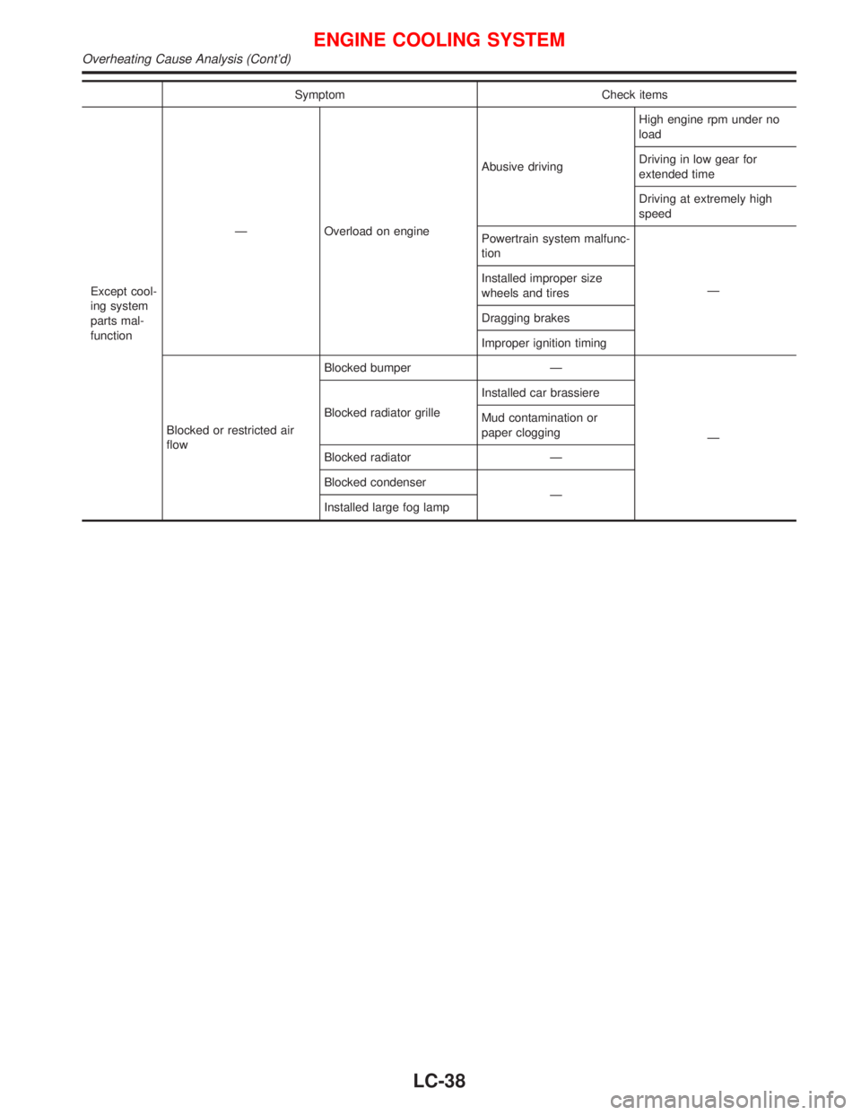
Symptom Check items
Except cool-
ing system
parts mal-
function—Overload on engineAbusive drivingHigh engine rpm under no
load
Driving in low gear for
extended time
Driving at extremely high
speed
Powertrain system malfunc-
tion
— Installed improper size
wheels and tires
Dragging brakes
Improper ignition timing
Blocked or restricted air
flowBlocked bumper—
— Blocked radiator grilleInstalled car brassiere
Mud contamination or
paper clogging
Blocked radiator—
Blocked condenser
—
Installed large fog lamp
ENGINE COOLING SYSTEM
Overheating Cause Analysis (Cont’d)
LC-38
Page 2191 of 2267
Precautions for SRS ªAIR BAGº and ªSEAT
BELT PRE-TENSIONERº Service
lDo not use electrical test equipment to check the SRS unless instructed to do in this Service Manual.
lBefore servicing the SRS, turn ignition switch ªOFFº, disconnect both battery cables and wait at least 3
minutes.
For approximately 3 minutes after the cables are removed, it is still possible for the air bag and seat belt
pre-tensioner to deploy. Therefore, do not work on any SRS connectors or wires until at least 3 minutes
have passed.
lDiagnosis sensor unit must always be installed with their arrow marks ªSº pointing towards the front of
the vehicle for proper operation. Also check diagnosis sensor unit for cracks, deformities or rust before
installation and replace as required.
lThe spiral cable must be aligned with the neutral position since its rotations are limited. Do not attempt
to turn steering wheel or column after removal of steering gear.
lHandle air bag module carefully. Always place driver's and passenger's air bag modules with the pad
side facing upward and place side air bag module (built-in type) standing with stud bolt side setting bot-
tom.
lConduct self-diagnosis to check entire SRS for proper function after replacing any components.
lAfter air bag inflates, the front instrument panel assembly should be replaced if damaged.
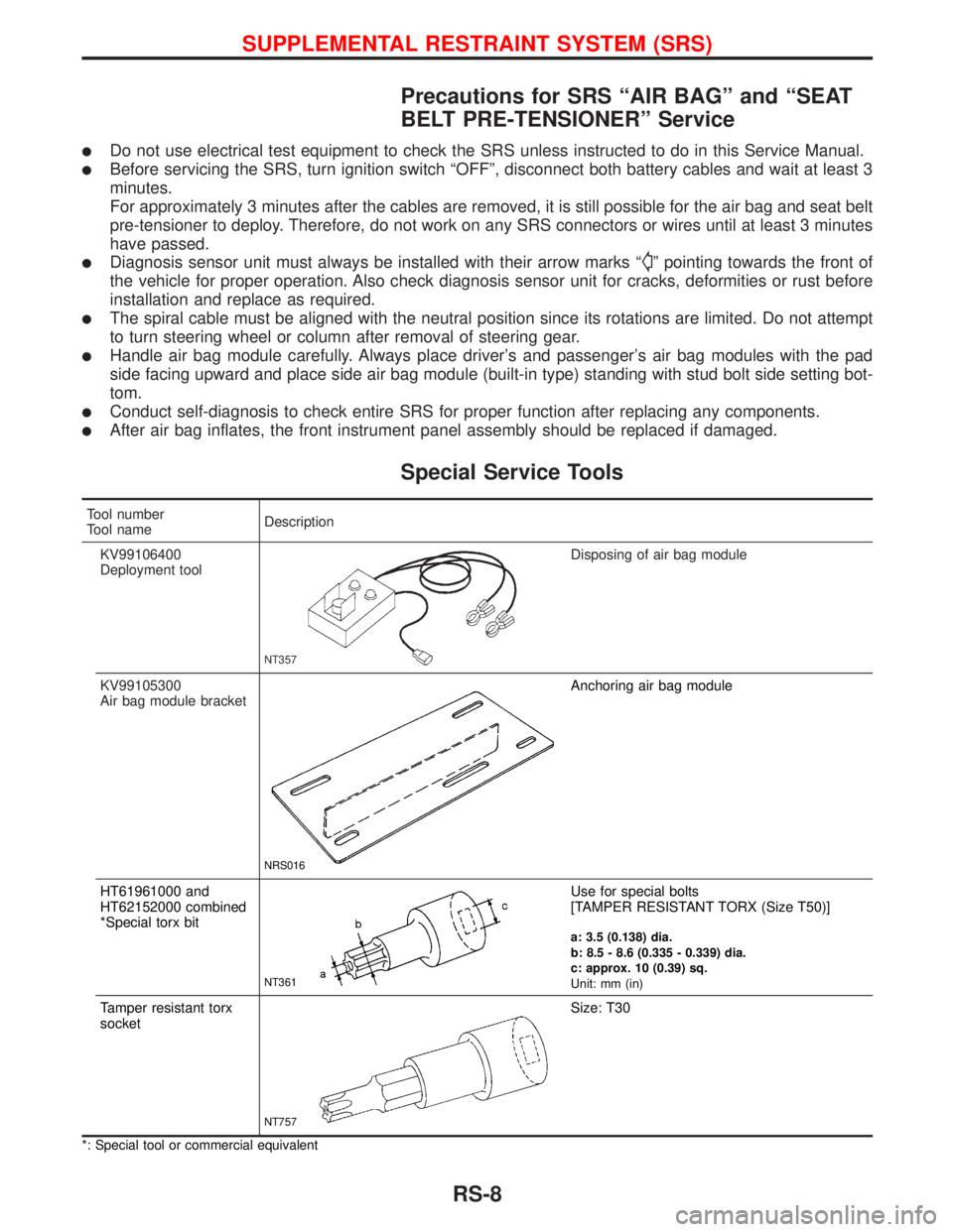
Special Service Tools
Tool number
Tool nameDescription
KV99106400
Deployment tool
NT357
Disposing of air bag module
KV99105300
Air bag module bracket
NRS016
Anchoring air bag module
HT61961000 and
HT62152000 combined
*Special torx bit
NT361
Use for special bolts
[TAMPER RESISTANT TORX (Size T50)]
a: 3.5 (0.138) dia.
b: 8.5 - 8.6 (0.335 - 0.339) dia.
c: approx. 10 (0.39) sq.
Unit: mm (in)
Tamper resistant torx
socket
NT757
Size: T30
*: Special tool or commercial equivalent
SUPPLEMENTAL RESTRAINT SYSTEM (SRS)
RS-8