window NISSAN PRIMERA 1999 Electronic Repair Manual
[x] Cancel search | Manufacturer: NISSAN, Model Year: 1999, Model line: PRIMERA, Model: NISSAN PRIMERA 1999Pages: 2267, PDF Size: 35.74 MB
Page 215 of 2267
BODY & TRIM
SECTION
BT
CONTENTS
PRECAUTIONS............................................................. 2
Service Notice............................................................ 2
Supplemental Restraint System (SRS)²AIR
BAG²and²SEAT BELT PRE-TENSIONER²............. 2
GENERAL SERVICING................................................. 3
Clip and Fastener ...................................................... 3
BODY END.................................................................... 5
Body Front End.......................................................... 5
Body Rear End and Opener ...................................... 7
DOOR........................................................................... 13
Front Door................................................................ 13
Rear Door ................................................................ 14
INSTRUMENT PANEL................................................. 15
INTERIOR TRIM.......................................................... 18
Side and Floor Trim ................................................. 18
Door Trim ................................................................. 24
Roof Trim ................................................................. 25
Trunk Room Trim ..................................................... 28
Luggage Room Trim ................................................ 29Back Door Trim ........................................................ 30
EXTERIOR................................................................... 31
SEAT............................................................................ 40
Front Seat ................................................................ 40
Heated Seat ............................................................. 42
Rear Seat................................................................. 43
SUNROOF.................................................................... 46
Trouble Diagnoses................................................... 49
WINDSHIELD AND WINDOWS.................................. 53
Windshield and Rear Window ................................. 54
Side Window ............................................................ 55
Back Door Window .................................................. 56
MIRROR....................................................................... 58
Door Mirror............................................................... 58
Rearview Mirror ....................................................... 59
BODY ALIGNMENT..................................................... 60
Engine Compartment ............................................... 60
Underbody ............................................................... 62
BT
Page 238 of 2267
Door Trim
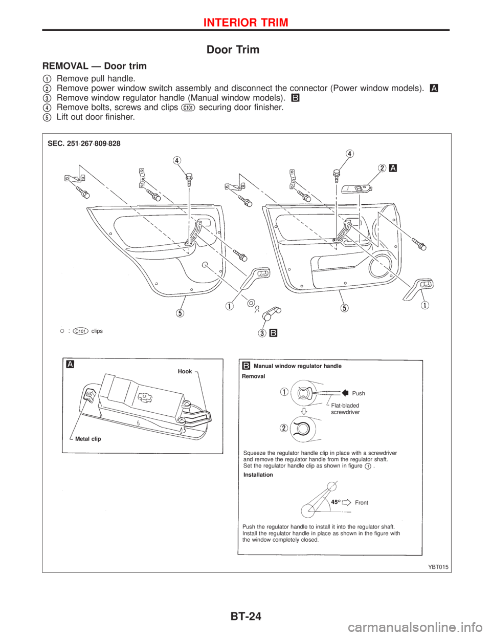
REMOVAL Ð Door trim
p1Remove pull handle.
p2Remove power window switch assembly and disconnect the connector (Power window models).
p3Remove window regulator handle (Manual window models).
p4Remove bolts, screws and clipsC101securing door finisher.
p5Lift out door finisher.
YBT015 clips
Metal clipHookManual window regulator handle
Removal
Push
Flat-bladed
screwdriver
Squeeze the regulator handle clip in place with a screwdriver
and remove the regulator handle from the regulator shaft.
Set the regulator handle clip as shown in figure
p1.
Installation
Front
Push the regulator handle to install it into the regulator shaft.
Install the regulator handle in place as shown in the figure with
the window completely closed.
SEC. 251×267×809×828
INTERIOR TRIM
BT-24
Page 249 of 2267
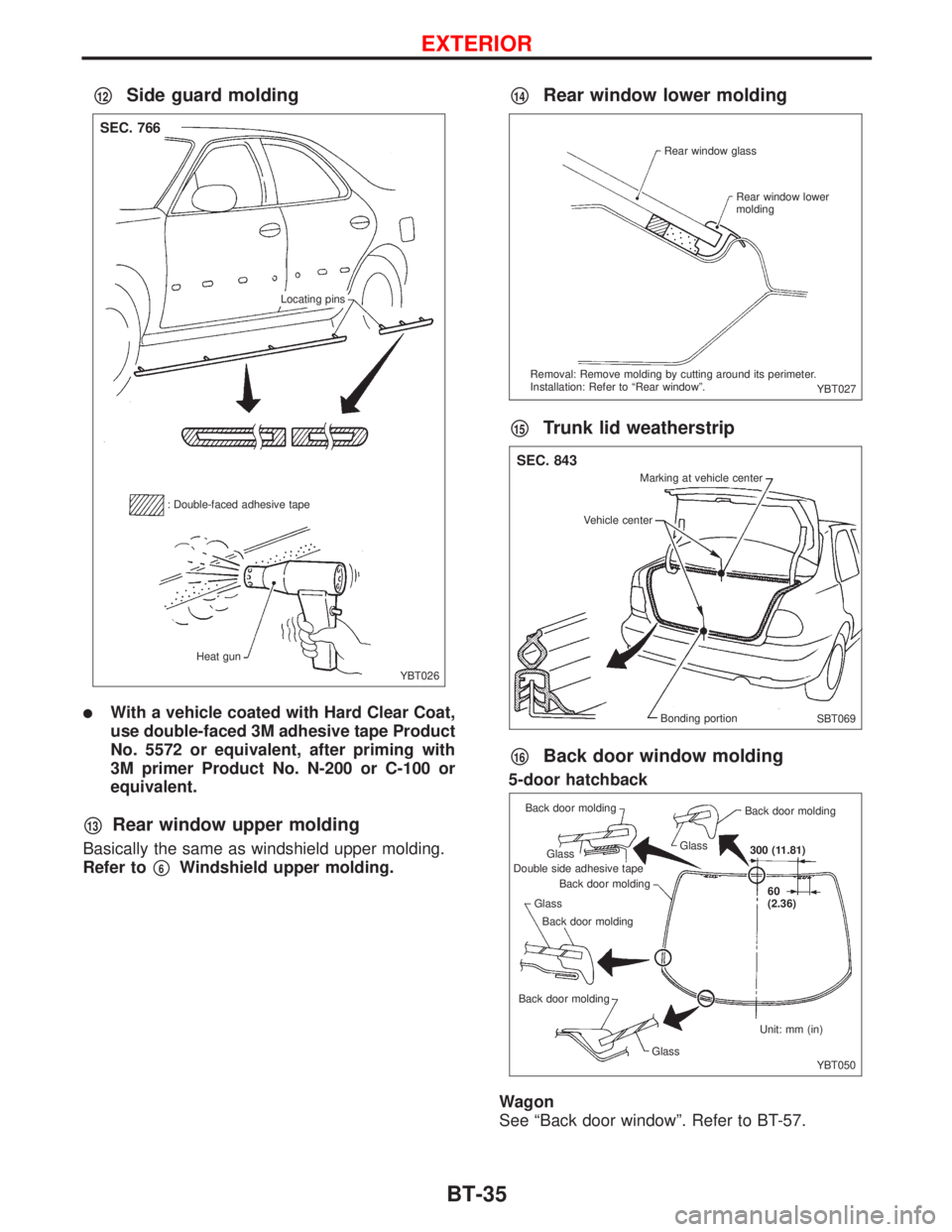
p12Side guard molding
lWith a vehicle coated with Hard Clear Coat,
use double-faced 3M adhesive tape Product
No. 5572 or equivalent, after priming with
3M primer Product No. N-200 or C-100 or
equivalent.
p13Rear window upper molding
Basically the same as windshield upper molding.
Refer to
p6Windshield upper molding.
p14Rear window lower molding
p15Trunk lid weatherstrip
p16Back door window molding
5-door hatchback
Wagon
See ªBack door windowº. Refer to BT-57.
YBT026
SEC. 766
Locating pins
: Double-faced adhesive tape
Heat gun
YBT027 Rear window glass
Rear window lower
molding
Removal: Remove molding by cutting around its perimeter.
Installation: Refer to ªRear windowº.
SBT069
SEC. 843
Marking at vehicle center
Vehicle center
Bonding portion
YBT050 300 (11.81)
60
(2.36)
Unit: mm (in)
Glass Back door moldingBack door molding GlassBack door molding Double side adhesive tapeGlass Back door molding
Back door molding
Glass
EXTERIOR
BT-35
Page 267 of 2267
REMOVAL
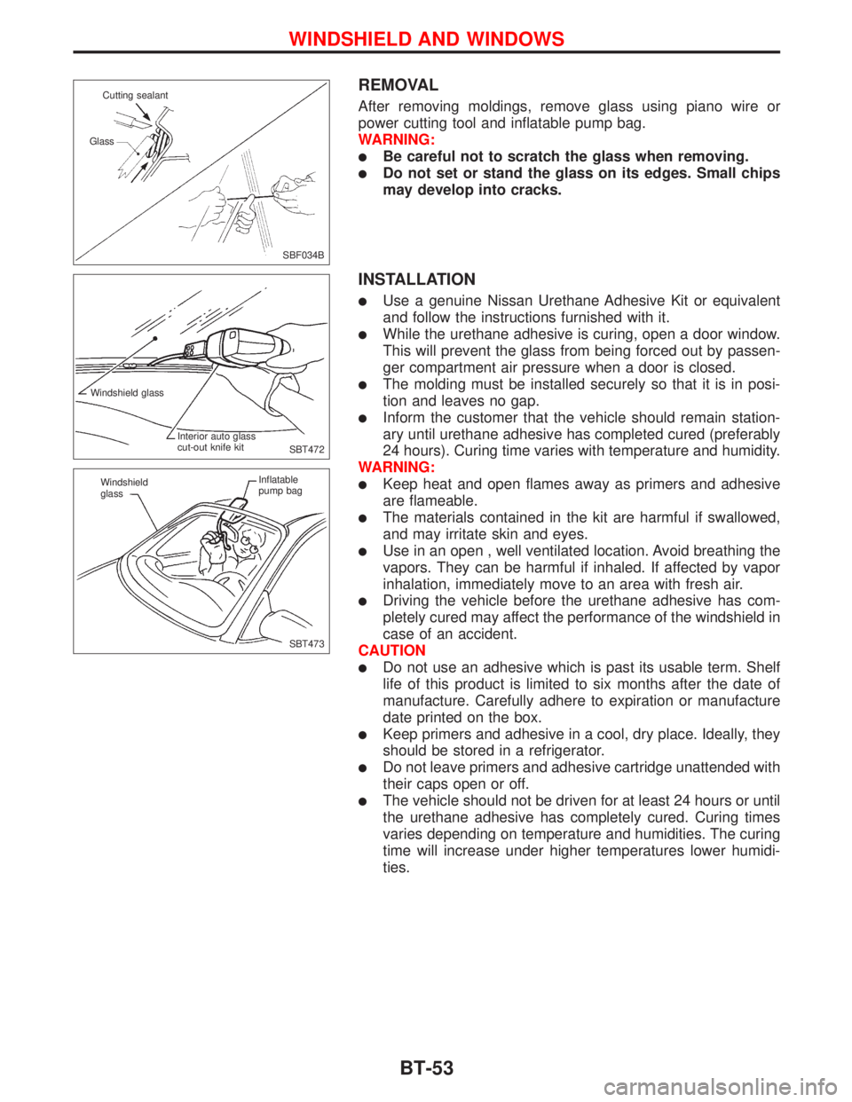
After removing moldings, remove glass using piano wire or
power cutting tool and inflatable pump bag.
WARNING:
lBe careful not to scratch the glass when removing.
lDo not set or stand the glass on its edges. Small chips
may develop into cracks.
INSTALLATION
lUse a genuine Nissan Urethane Adhesive Kit or equivalent
and follow the instructions furnished with it.
lWhile the urethane adhesive is curing, open a door window.
This will prevent the glass from being forced out by passen-
ger compartment air pressure when a door is closed.
lThe molding must be installed securely so that it is in posi-
tion and leaves no gap.
lInform the customer that the vehicle should remain station-
ary until urethane adhesive has completed cured (preferably
24 hours). Curing time varies with temperature and humidity.
WARNING:
lKeep heat and open flames away as primers and adhesive
are flameable.
lThe materials contained in the kit are harmful if swallowed,
and may irritate skin and eyes.
lUse in an open , well ventilated location. Avoid breathing the
vapors. They can be harmful if inhaled. If affected by vapor
inhalation, immediately move to an area with fresh air.
lDriving the vehicle before the urethane adhesive has com-
pletely cured may affect the performance of the windshield in
case of an accident.
CAUTION
lDo not use an adhesive which is past its usable term. Shelf
life of this product is limited to six months after the date of
manufacture. Carefully adhere to expiration or manufacture
date printed on the box.
lKeep primers and adhesive in a cool, dry place. Ideally, they
should be stored in a refrigerator.
lDo not leave primers and adhesive cartridge unattended with
their caps open or off.
lThe vehicle should not be driven for at least 24 hours or until
the urethane adhesive has completely cured. Curing times
varies depending on temperature and humidities. The curing
time will increase under higher temperatures lower humidi-
ties.
SBF034B Cutting sealant
Glass
SBT472 Windshield glass
Interior auto glass
cut-out knife kit
SBT473 Windshield
glassInflatable
pump bag
WINDSHIELD AND WINDOWS
BT-53
Page 268 of 2267
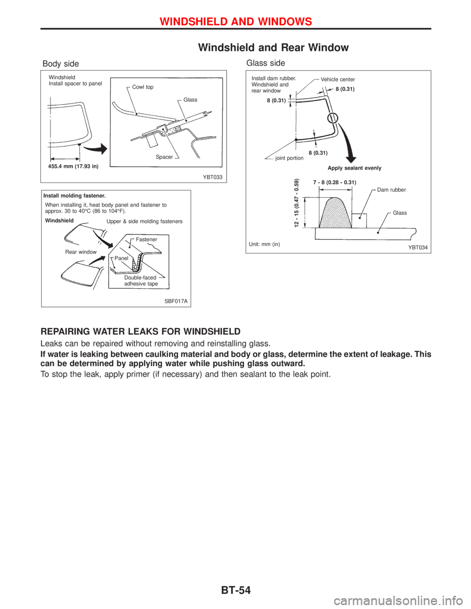
Windshield and Rear Window
REPAIRING WATER LEAKS FOR WINDSHIELD
Leaks can be repaired without removing and reinstalling glass.
If water is leaking between caulking material and body or glass, determine the extent of leakage. This
can be determined by applying water while pushing glass outward.
To stop the leak, apply primer (if necessary) and then sealant to the leak point.
YBT033
Body side
SBF017A
Glass side
YBT034
Windshield
Install spacer to panel
Cowl top
Glass
Spacer
455.4 mm (17.93 in)Install dam rubber.
Windshield and
rear window
8 (0.31)Vehicle center
joint portion
Apply sealant evenly
12 - 15 (0.47 - 0.59)
Dam rubber
Glass
Unit: mm (in)7 - 8 (0.28 - 0.31) 8 (0.31)8 (0.31)Install molding fastener.
When installing it, heat body panel and fastener to
approx. 30 to 40ÉC (86 to 104ÉF).
Windshield
Upper & side molding fasteners
Fastener
Panel
Double-faced
adhesive tape Rear window
WINDSHIELD AND WINDOWS
BT-54
Page 269 of 2267
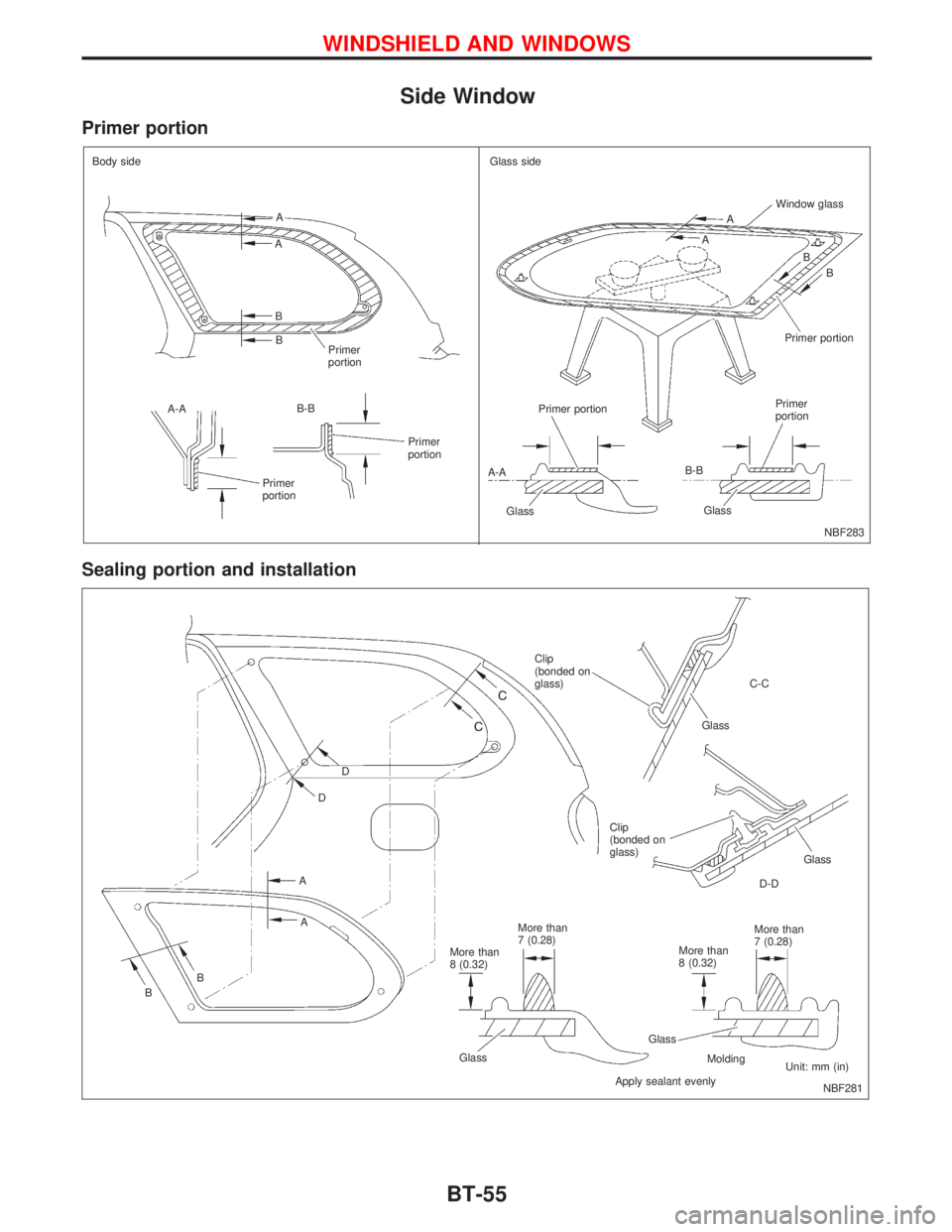
Side Window
Primer portion
Sealing portion and installation
NBF283 Body side
.A
A
B
B
Primer
portion
A-AB-B
Primer
portion
Primer
portionGlass side
A
AWindow glass
B
Primer portion
Primer portion
A-A
GlassB-B
GlassPrimer
portionB
D
D
A
A
B
BClip
(bonded on
glass)C-C
Glass
Clip
(bonded on
glass)
Glass
D-D
More than
7 (0.28)
More than
8 (0.32)
Glass
Molding
Apply sealant evenlyUnit: mm (in) More than
7 (0.28)
More than
8 (0.32)
Glass
NBF281
WINDSHIELD AND WINDOWS
BT-55
Page 270 of 2267
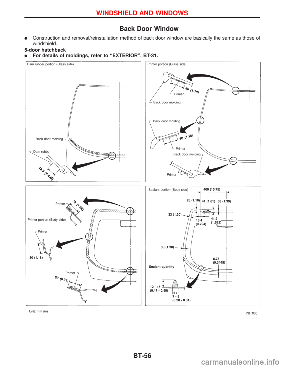
Back Door Window
lConstruction and removal/reinstallation method of back door window are basically the same as those of
windshield.
5-door hatchback
lFor details of moldings, refer to ªEXTERIORº, BT-31.
YBT035 Primer portion (Body side)Primer
Primer
30 (1.18)
PrimerSealant quantity
12-15
(0.47 - 0.59)
7-8
(0.28 - 0.31) 33 (1.30)33 (1.30)
8.75
(0.3445) 18.4
(0.724)41.2
(1.622) 28 (1.10)
41 (1.61) 33 (1.30)400 (15.75)
Sealant portion (Body side) Primer portion (Glass side) Dam rubber portion (Glass side)
Back door molding
Dam rubberPrimer
Back door molding
Back door molding
Primer
Back door molding
Primer
Unit: mm (in)
WINDSHIELD AND WINDOWS
BT-56
Page 271 of 2267
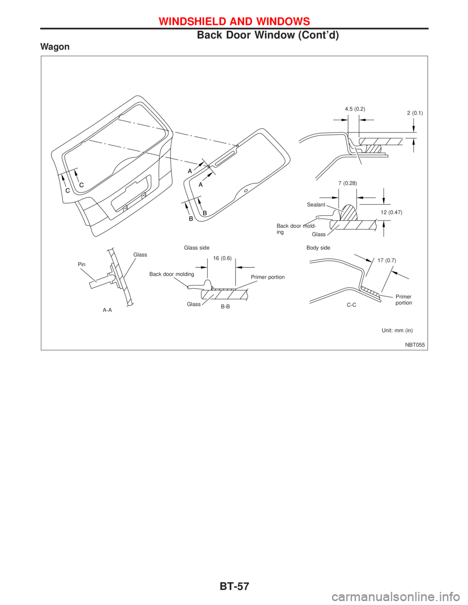
Wagon
NBT055
Glass
Pin
.A-AGlass side
16 (0.6)
Primer portion
Glass
B-BBody side
17 (0.7)
Primer
portion
C-C
Unit: mm (in) Glass Sealant7 (0.28)
12 (0.47) 4.5 (0.2)
2 (0.1)
Back door moldingBack door mold-
ing
WINDSHIELD AND WINDOWS
Back Door Window (Cont'd)
BT-57
Page 475 of 2267
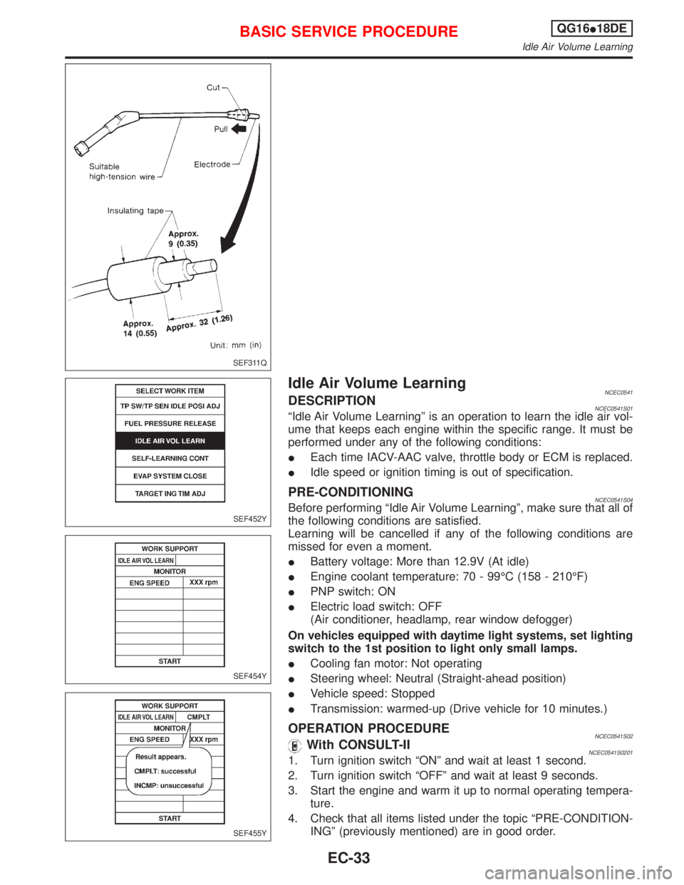
Idle Air Volume LearningNCEC0541DESCRIPTIONNCEC0541S01ªIdle Air Volume Learningº is an operation to learn the idle air vol-
ume that keeps each engine within the specific range. It must be
performed under any of the following conditions:
IEach time IACV-AAC valve, throttle body or ECM is replaced.
IIdle speed or ignition timing is out of specification.
PRE-CONDITIONINGNCEC0541S04Before performing ªIdle Air Volume Learningº, make sure that all of
the following conditions are satisfied.
Learning will be cancelled if any of the following conditions are
missed for even a moment.
IBattery voltage: More than 12.9V (At idle)
IEngine coolant temperature: 70 - 99ÉC (158 - 210ÉF)
IPNP switch: ON
IElectric load switch: OFF
(Air conditioner, headlamp, rear window defogger)
On vehicles equipped with daytime light systems, set lighting
switch to the 1st position to light only small lamps.
ICooling fan motor: Not operating
ISteering wheel: Neutral (Straight-ahead position)
IVehicle speed: Stopped
ITransmission: warmed-up (Drive vehicle for 10 minutes.)
OPERATION PROCEDURENCEC0541S02With CONSULT-IINCEC0541S02011. Turn ignition switch ªONº and wait at least 1 second.
2. Turn ignition switch ªOFFº and wait at least 9 seconds.
3. Start the engine and warm it up to normal operating tempera-
ture.
4. Check that all items listed under the topic ªPRE-CONDITION-
INGº (previously mentioned) are in good order.
SEF311Q
SEF452Y
SEF454Y
SEF455Y
BASIC SERVICE PROCEDUREQG16I18DE
Idle Air Volume Learning
EC-33
Page 514 of 2267
Basic InspectionNCEC0038Precaution:
Perform Basic Inspection without electrical or mechanical
loads applied;
IHeadlamp switch is OFF,
On vehicle equipped with daytime light system, set lighting
switch to the 1st position to light only small lamps.
IAir conditioner switch is OFF,
IRear window defogger switch is OFF,
ISteering wheel is in the straight-ahead position, etc.
1 INSPECTION START
1. Check service records for any recent repairs that may indicate a related problem, or a current need for scheduled
maintenance.
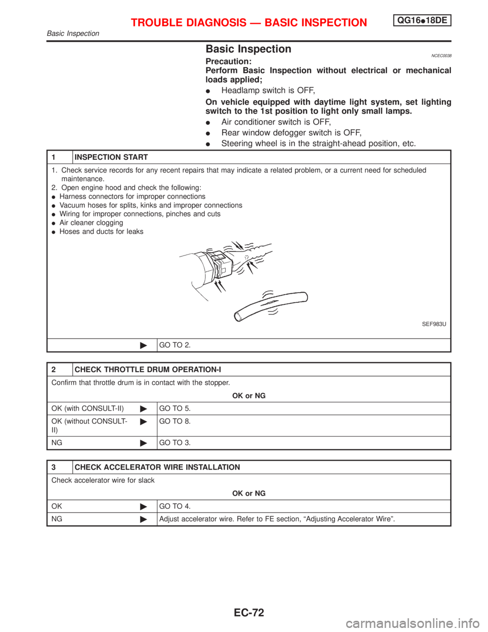
2. Open engine hood and check the following:
IHarness connectors for improper connections
IVacuum hoses for splits, kinks and improper connections
IWiring for improper connections, pinches and cuts
IAir cleaner clogging
IHoses and ducts for leaks
SEF983U
©GO TO 2.
2 CHECK THROTTLE DRUM OPERATION-I
Confirm that throttle drum is in contact with the stopper.
OK or NG
OK (with CONSULT-II)©GO TO 5.
OK (without CONSULT-
II)©GO TO 8.
NG©GO TO 3.
3 CHECK ACCELERATOR WIRE INSTALLATION
Check accelerator wire for slack
OK or NG
OK©GO TO 4.
NG©Adjust accelerator wire. Refer to FE section, ªAdjusting Accelerator Wireº.
TROUBLE DIAGNOSIS Ð BASIC INSPECTIONQG16I18DE
Basic Inspection
EC-72