diagram NISSAN PULSAR 1987 Workshop Manual
[x] Cancel search | Manufacturer: NISSAN, Model Year: 1987, Model line: PULSAR, Model: NISSAN PULSAR 1987Pages: 238, PDF Size: 28.91 MB
Page 4 of 238

FRONT SUSPENSION............................ 156
Specifications......................................................... 156
Front suspension tr ouble shooting ........................ 156
Description ............................................................ 157
Steering knuckle.................................................... 157
Suspension unit..................................................... 159
Control arm ........................................................... 161
Stabiliser bar ........................................................ 162
Suspension and steering angles .......................... 163
REAR SUSPENSION................................ 164
Specifications ........................................................ 164
Rear suspension tr ouble shooting ........................ 164
Description ............................................................ 165
Rear hub ............................................................... 166
Suspension unit .................................................... 167
Control arm ........................................................... 169
Knuckle assembly.................................................. 170
Stabiliser bar ........................................................ 170
Rear wheel alignment ........................................... 171
BRAKES...................................................... 172
Specifications......................................................... 172
Brakes trouble shooting ........................................ 172
Description ............................................................ 174
Master cyli nder...................................................... 175
Brake servo unit .................................................... 177
Front brakes ......................................................... 178
Rear disc brakes................................................... 181
Rear drum brakes ................................................. 184
Handbrake cable and le ver assembly ................... 186
Brake adjustments ................................................ 187
Brake pedal ........................................................... 187
Hydraulic system................................................... 188
ELECTRICAL SYSTEM............................ 190
Specifications......................................................... 190
Battery and charging system trouble shooting ....... 190
Battery and starting system trouble shooting ........ 191
Lighting system trouble shooting ........................... 192
Turn signal lamp trouble shooting ........................ 192
Test equipment and so me applications................. 193
Battery ................................................................... 194
Alternator ............................................................... 196
Starter motor ......................................................... 201
Ignition system ...................................................... 206
Steering wheel ....................................................... 206
Switches and controls........................................... 206
Instrument cluster.................................................. 209
Blower fan .............................................................. 209
Radio/cassette...................................................... 209
lamp units ............................................................ 210
Windscreen wiper ................................................. 213
Fuses, fusible links and relays ............................. 215
Trailer wiring ......................................................... 216
Wiring diagrams ................................................... 218
BODY........................................................... 225
Windscreen and re ar glass .................................. 225
Front doors ........................................................... 225
Rear doors............................................................ 228
Engine bonnet...................................................... 231
Tailgate and lock — hatchback ............................ 231
Luggage compartment lid and lock — sedan ........ 233
Radiator grille.............................................................. 234
Centre console...................................................... 234 Dashboard ............................................................ 235
Scat belts ............................................................. 236
Seats .................................................................... 236
Vehicle cleaning ........................................................... 237
CONVERSION TABLES.......................... 238
Page 24 of 238
24 Wheels and Tires
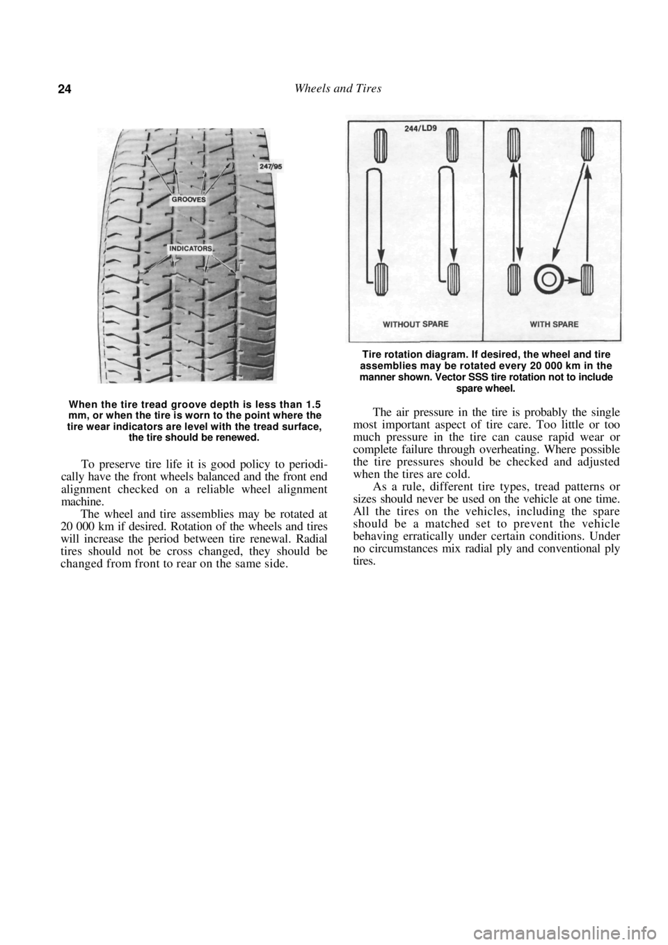
When the tire tread groove depth is less than 1.5
mm, or when the tire is worn to the point where the
tire wear indicators are level with the tread surface,
the tire should be renewed.
To preserve tire life it is good policy to periodi-
cally have the front wheels balanced and the front end
alignment checked on a reliable wheel alignment
machine.
The wheel and tire assemblies may be rotated at
20 000 km if desired. Rotation of the wheels and tires
will increase the period between tire renewal. Radial
tires should not be cross changed, they should be
changed from front to rear on the same side.
Tire rotation diagram. If desired, the wheel and tire
assemblies may be rotated every 20 000 km in the
manner shown. Vector SSS tire rotation not to include
spare wheel.
The air pressure in the tire is probably the single
most important aspect of tire care. Too little or too
much pressure in the tire can cause rapid wear or
complete failure through overheating. Where possible
the tire pressures should be checked and adjusted
when the tires are cold.
As a rule, different tire types, tread patterns or
sizes should never be used on the vehicle at one time.
All the tires on the vehicles, including the spare
should be a matched set to prevent the vehicle
behaving erratically under certain conditions. Under
no circumstances mix radial ply and conventional ply
tires.
Page 80 of 238
Cooling and Heating Systems
11. BLOWER FAN
TO REMOVE AND INSTAL
(1) Disconnect the negative battery terminal.
(2) Working below the glov e compartment, dis-
connect the wiring connector to the blower fan motor.
(3) Remove the bolts retaining the blower fan
motor and carefully lower the motor while disconnect-
ing the drain hose.
Installation is a reversal of the removal procedure
with attention to the following points:
( t ) Tighten all bolts securely.
(2) Check that the blow er fan operates correctly.
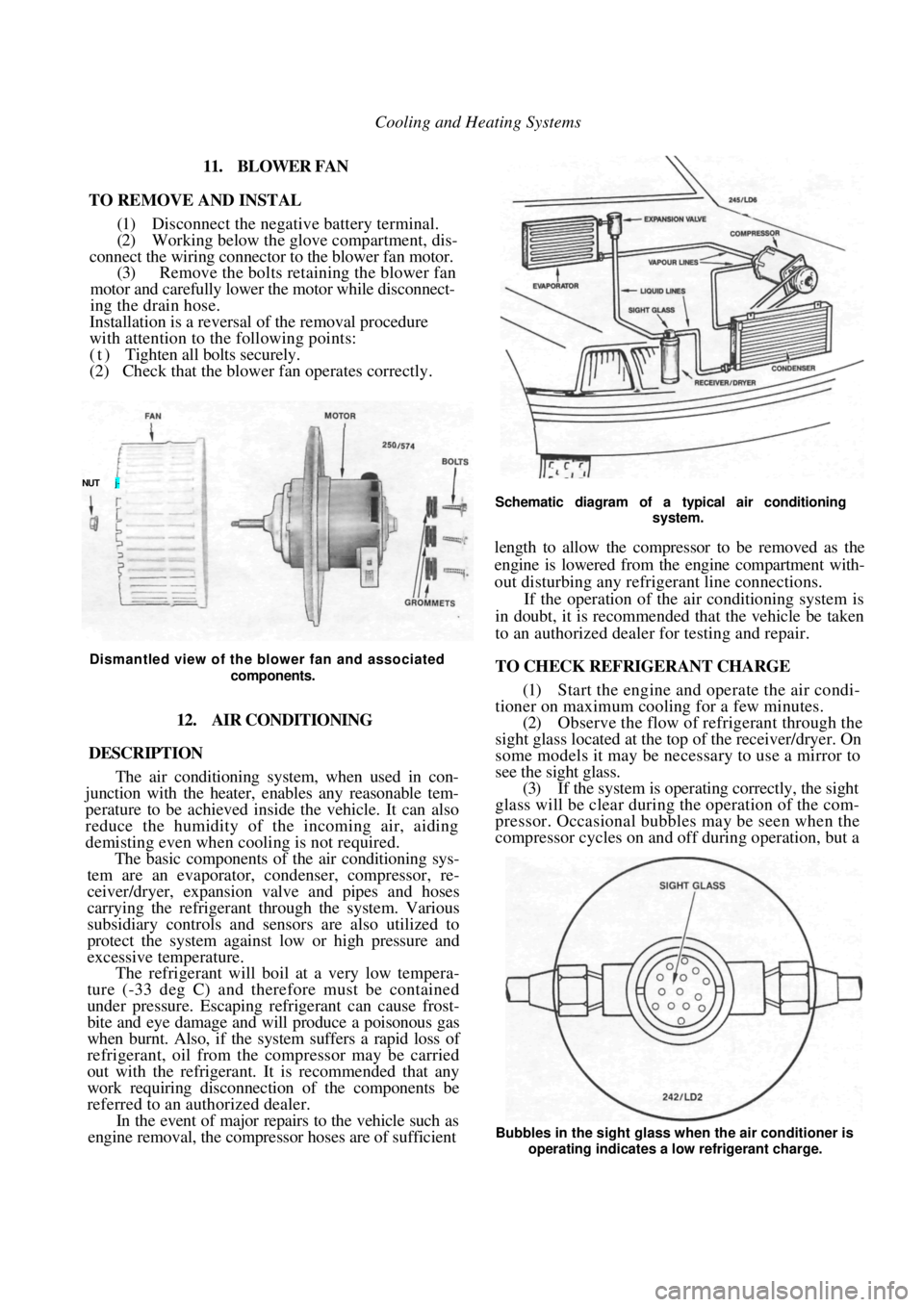
Dismantled view of the blower fan and associated
components.
12. AIR CONDITIONING
DESCRIPTION
The air conditioning system, when used in con-
junction with the heater, enables any reasonable tem-
perature to be achieved inside the vehicle. It can also
reduce the humidity of the incoming air, aiding
demisting even when cooling is not required.
The basic components of the air conditioning sys-
tem are an evaporator, co ndenser, compressor, re-
ceiver/dryer, expansion valve and pipes and hoses
carrying the refrigerant through the system. Various
subsidiary controls and sensors are also utilized to
protect the system against low or high pressure and
excessive temperature.
The refrigerant will boil at a very low tempera-
ture (-33 deg C) and therefore must be contained
under pressure. Escaping refrigerant can cause frost-
bite and eye damage and will produce a poisonous gas
when burnt. Also, if the system suffers a rapid loss of
refrigerant, oil from the compressor may be carried
out with the refrigerant. It is recommended that any
work requiring disconnection of the components be
referred to an au thorized dealer.
In the event of major repair s to the vehicle such as
engine removal, the compress or hoses are of sufficient
Schematic diagram of a typical air conditioning
system.
length to allow the compressor to be removed as the
engine is lowered from the engine compartment with-
out disturbing any refrigerant line connections.
If the operation of the air conditioning system is
in doubt, it is recommended that the vehicle be taken
to an authorized dealer for testing and repair.
TO CHECK REFRIGERANT CHARGE
(1) Start the engine and operate the air condi-
tioner on maximum cooling for a few minutes.
(2) Observe the flow of refrigerant through the
sight glass located at the top of the receiver/dryer. On
some models it may be necessary to use a mirror to
see the sight glass. (3) If the system is operating correctly, the sight
glass will be clear during the operation of the com-
pressor. Occasional bubbles may be seen when the
compressor cycles on and off during operation, but a
NUT j-
Bubbles in the sight glass when the air conditioner is
operating indicates a low refrigerant charge.
Page 86 of 238
86 Fuel and Engine Management
other. The fuel pressure is maintained at a constant
pressure relevant to the manifold vacuum. A dispos-
able paper element fuel filter is mounted on the engine
bulkhead.
The amount of fuel injected is relevant to the time
the injector remains open. The basic time the injector
remains open is governed by the control unit which
uses information from the various sensors to give
optimum engine efficiency for given conditions.
The idle air control (IAC) valve controls the fast
idle speed during engine warm up and maintains the
basic idle speed at a set value by compensating for
loads such as air conditioning or the selection of Drive
on automatic transaxle models.
The throttle body assembly is mounted to the
inlet manifold and controls the amount of air entering
the engine by the action of the throttle valve.
Efficient operation of the EFI system depends on
accurate signals being receiv ed by the control unit and
controlled air flow beyond the throttle valve. There-
fore it is essential that all air, fuel and electrical
connections be clean and tight.
3. SERVICE PRECAUTIONS AND
PROCEDURES
Electronic ignition systems can produce danger-
ously high voltages in both the primary and secondary
circuits. For this reason, extreme care must be taken
when working on or near the ignition system.
Do not start the engine if the battery terminals are
not clean and tight.
Do not use the fast charge or boost settings on a
battery charger to start the engine.
Do not disconnect the battery terminals while the
engine is running.
Disconnect the battery terminals before charging
the battery.
Disconnect the negative ba ttery terminal before
working on the engine management system.
Do not subject the control unit to temperatures
above 80 deg C.
Ensure that all wiring connectors are clean and
tight.
Disconnect the battery terminals and the control
unit wiring connectors before attempting any welding
operations.
Do not direct a steam cleaning or pressure
washing nozzle at engine management components
when cleaning the engine.
Ensure that the ignition is Off prior to disconnect-
ing the battery terminals, fusible links or the control
unit wiring connectors.
TO CONNECT ELECTRICAL TEST
EQUIPMENT
NOTE: Some types of tachometers, timing
lights and ignition system analysers are not
compatible with this engine management
system and may result in incorrect readings.
It is therefore recommended that the man-
ufacturer of the lest equipment be consulted
before proceeding to use the equipment.
If a test procedure requires the use of a
test lamp or voltmeter, ensure that only the
specified instrument is used to prevent mis-
leading diagnosis.
MULTIMETER
It is essential that in all tests where voltage or
resistance is to be measur ed, a digital display multi-
meter with a minimum 10 megohms impedance be
used.
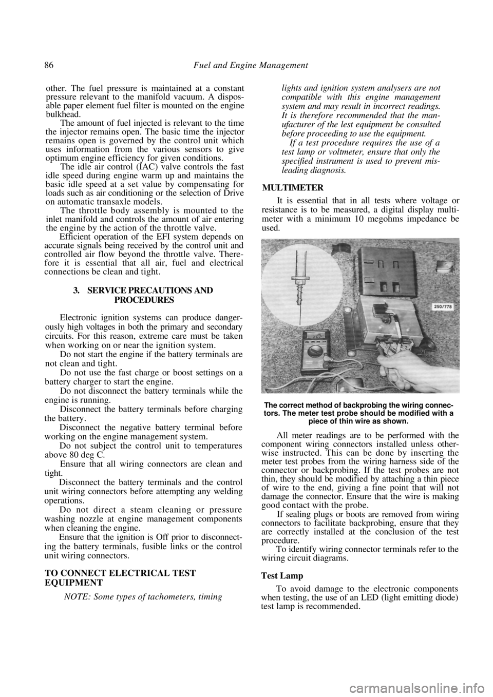
The correct method of backprobing the wiring connec-
tors. The meter test probe should be modified with a piece of thin wire as shown.
All meter readings are to be performed with the
component wiring connectors installed unless other-
wise instructed. This can be done by inserting the
meter test probes from the wiring harness side of the
connector or backprobing. If the test probes are not
thin, they should be modified by attaching a thin piece
of wire to the end, giving a fine point that will not
damage the connector. Ensure that the wire is making
good contact with the probe.
If sealing plugs or boots are removed from wiring
connectors to facilitate bac kprobing, ensure that they
are correctly installed at the conclusion of the test
procedure.
To identify wiring connector terminals refer to the
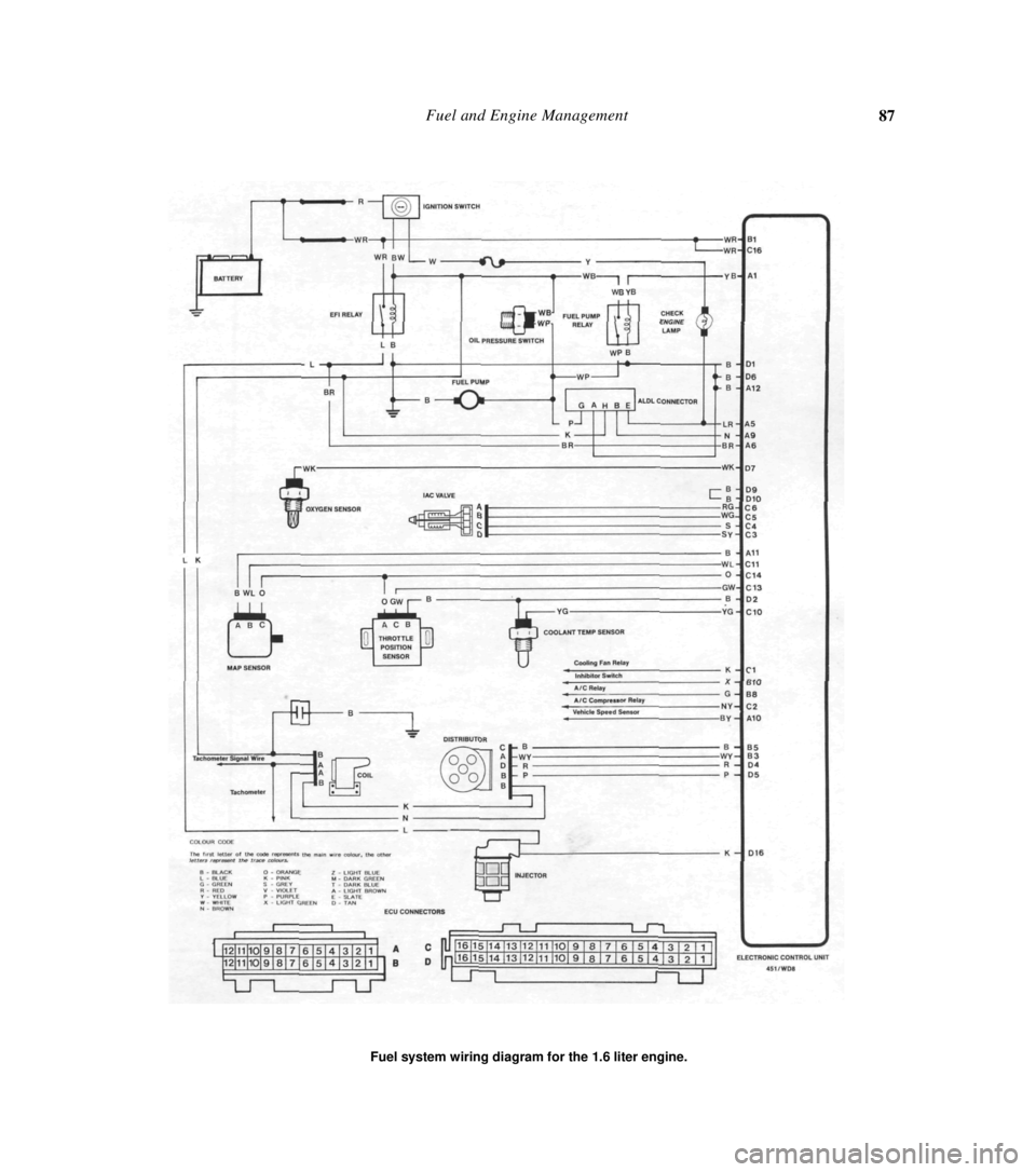
wiring circuit diagrams.
Test Lamp
To avoid damage to the electronic components
when testing, the use of an LED (light emitting diode)
test lamp is recommended.
Page 87 of 238
Fuel and Engine Management 87
Fuel system wiring diagram for the 1.6 liter engine.
Page 88 of 238
88 Fuel and Engine Management
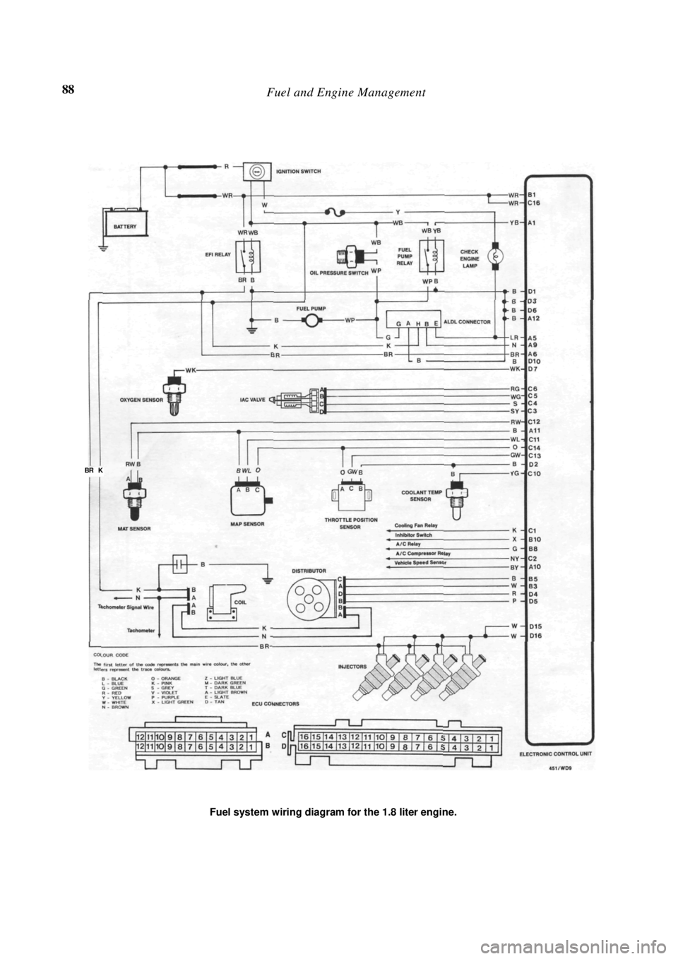
Fuel system wiring diagram for the 1.8 liter engine.
BR K
Page 109 of 238
Fuel and Engine Management 109
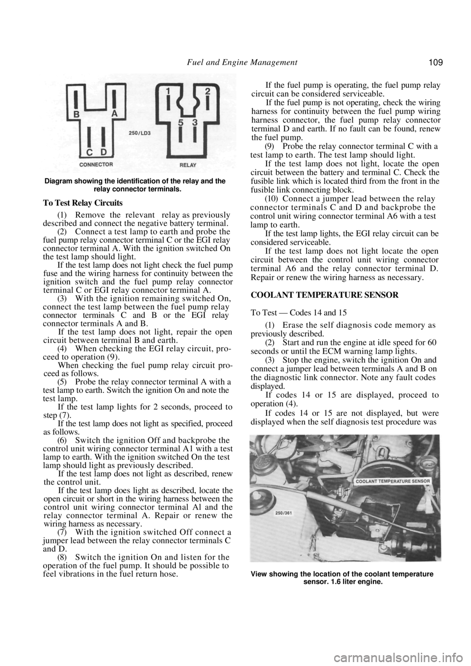
Diagram showing the identification of the relay and the relay connector terminals.
To Test Relay Circuits
(1) Remove the relevant relay as previously
described and connect the ne gative battery terminal.
(2) Connect a test lamp to earth and probe the
fuel pump relay connector terminal C or the EGI relay
connector terminal A. With the ignition switched On
the test lamp should light. If the test lamp does not light check the fuel pump
fuse and the wiring harness for continuity between the
ignition switch and the fuel pump relay connector
terminal C or EGI rela y connector terminal A.
(3) With the ignition remaining switched On,
connect the test lamp between the fuel pump relay
connector terminals C and B or the EGI relay
connector terminals A and B.
If the test lamp does not light, repair the open
circuit between terminal B and earth.
(4) When checking the EGI relay circuit, pro-
ceed to operation (9).
When checking the fuel pu mp relay circuit pro-
ceed as follows.
(5) Probe the relay connector terminal A with a
test lamp to earth. Switch the ignition On and note the
test lamp.
If the test lamp lights for 2 seconds, proceed to
step (7).
If the test lamp does not light as specified, proceed
as follows.
(6) Switch the ignition Off and backprobe the
control unit wiring connector terminal A1 with a test
lamp to earth. With the ignition switched On the test
lamp should light as previously described.
If the test lamp does not light as described, renew
the control unit.
If the test lamp does light as described, locate the
open circuit or short in the wiring harness between the
control unit wiring connector terminal Al and the
relay connector terminal A. Repair or renew the
wiring harness as necessary.
(7) With the ignition switched Off connect a
jumper lead between the relay connector terminals C
and D. (8) Switch the ignition On and listen for the
operation of the fuel pump. It should be possible to
feel vibrations in the fuel return hose. If the fuel pump is operating, the fuel pump relay
circuit can be considered serviceable.
If the fuel pump is not operating, check the wiring
harness for continuity between the fuel pump wiring
harness connector, the fuel pump relay connector
terminal D and earth. If no fault can be found, renew
the fuel pump.
(9) Probe the relay connector terminal C with a
test lamp to earth. The test lamp should light.
If the test lamp does not light, locate the open
circuit between the battery and terminal C. Check the
fusible link which is located third from the front in the
fusible link connecting block.
(10) Connect a jumper lead between the relay
connector terminals C and D and backprobe the
control unit wiring connector terminal A6 with a test
lamp to earth.
If the test lamp lights, the EGI relay circuit can be
considered serviceable.
If the test lamp does not light locate the open
circuit between the contro l unit wiring connector
terminal A6 and the relay connector terminal D.
Repair or renew the wiring harness as necessary.
COOLANT TEMPERATURE SENSOR
To Test — Codes 14 and 15
(1) Erase the self diagnosis code memory as
previously described. (2) Start and run the engine at idle speed for 60
seconds or until the ECM warning lamp lights.
(3) Stop the engine, switch the ignition On and
connect a jumper lead between terminals A and B on
the diagnostic link connect or. Note any fault codes
displayed. If codes 14 or 15 are displayed, proceed to
operation (4).
If codes 14 or 15 are not displayed, but were
displayed when the self diagnosis test procedure was
View showing the location of the coolant temperature
sensor. 1.6 liter engine.
Page 163 of 238
Front Suspension 163
(2) Ensure that the stabilizer bar links are in
good condition. Renew if necessary.
(3) When installing the stabilizer bar ensure that
the links are installed perpendicular to the control arm
with the ball joint socket face parallel to the end of the
stabilizer bar. (4) Ensure that the brackets are installed with
the flat portion facing towards the front of the vehicle.
Tighten the retaining bolts securely.
7. SUSPENSION AND STEERING ANGLES
ADJUSTMENT
NOTE: Extensive knowledge and special-
ised equipment are required to measure and
correct the suspension and steering angles
with the exception of the front wheel toe in.
Therefore, as it is not a viable proposition
for the average person to carry out a com-
plete wheel alignment, the vehicle should be
taken to a wheel alignment specialist.
Prior to carrying out a wheel alignment, a thor-
ough inspection of the steering linkage, front hub
bearings, ball joints and suspension units should be
carried out. Faulty components should be renewed or
repaired as necessary.
The tread of the front ti res should be examined
for excessive or uneven wear as certain conditions of
tire wear are indicative of damaged or worn compo-
nents in the suspension, stee ring linkage and/or wheels
and bearings. Refer to the heading Tire Wear Trouble
Shooting in the Wheels and Tires section. If the tires
are found to be defective, renew them with serviceable
lyres.
TO CHECK AND ADJUST TOE IN/OUT
NOTE: The vehicle s hould be unladen ex-
cept for the normal amount of fuel and with
the tires inflated to the correct pressures.
(1) With the vehicle on a level floor, raise the
front of the vehicle and s upport it on chassis stands.
(2) Spin each front wheel in turn and using a
piece of chalk, mark a line around the periphery of
each tire as near to the centre as possible. (3) Lower the vehicle to the ground and bounce
the front several times to stabilize the suspension. (4) Set the wheels in the straight ahead position.
(5) Mark the centre chalk line on both tires at a
point approximately 200 mm above the floor and
forward of the suspension. (6) Using a tape measure, measure and record
the distance between the two marked points on the
tire centers.
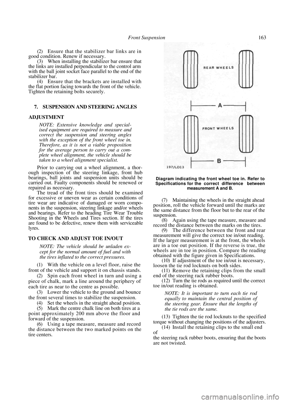
Diagram indicating the front wheel toe in. Refer to
Specifications for the correct difference between
measurement A and B.
(7) Maintaining the wheels in the straight ahead
position, roll the vehicle forward until the marks are
the same distance from the floor but to the rear of the
suspension. (8) Again using the tape measure, measure and
record the distance between the marks on the tires.
(9) The difference between the front and rear
measurement will give the correct toe in/out reading.
If the larger measurement is at the front, the wheels
are in a toe out position. If the reverse is true, the
wheels are in toe in position. Compare the reading
obtained with the figure given in Specifications.
(10) If adjustment of the to e in/out is necessary,
loosen the tie rod locknuts on both sides. (11) Remove the retaining clips from the small
end of the steering rack rubber boots. (12) Turn the tie rods as required until the correct
toe in/out reading is obtained.
NOTE: It is important to turn each tie rod
equally to maintain the central position of
the steering gear. Ensure that the lengths of
the tie rods are the same.
(13) Tighten the tie rod locknuts to the specified
torque without changing the positions of the adjusters.
(14) Install the retaining clips to the small end
of
the steering rack rubber boots, ensuring that the boots
are not twisted.
Page 171 of 238
Rear Suspension 171
Installation is a reversal of the removal procedure
with attention to the following points:
(1) When installing the stabilizer bar to the
knuckle assembly bushes, ensu re that the thicker bush
is installed to the front of the knuckle assembly. Install
the rear bush, washers and nut but do not tighten at
this stage. (2) Install the stabil izer bar mounting
brackets,
ensuring that the end with the large bevel is facing the
front of the vehicle. Tighte n the retaining bolts to the
specified torque. (3) Using a new gasket, install the intermediate
exhaust pipe to the catalytic converter, ensuring that
the earth wire terminal is installed, and tighten the
bolts securely. Install the exhaust mounting
retaining
bolt. (4) Install the rear wheels and lower the
vehicle
to the ground. With the wei ght of the vehicle on the
road wheels, tighten the stabilizer bar retaining nuts to
the specified torque.
8. REAR WHEEL ALIGNMENT
Specialized equipment is required to measure the
rear wheel alignment. It is therefore recommended
that the vehicle be referred to a specialist suspension
workshop or an authorized dealer for measurement
and adjustment. The suspension components should
be inspected and renewed as necessary prior to having
the wheel alignment checked. If any suspension com-
ponents are renewed, the re ar wheel toe out may be
temporarily adjusted as described below.
TO INSPECT
Examine the tread of the tires. Excessive or
uneven wear will indicate misalignment or damaged
or worn components. Refer to the Tire Wear Trouble
Shooting Chart in the Wheels and Tires section for
possible causes and renew the faulty components.
Badly worn tires should be renewed prior to
having the wheel alignment checked.
TO CHECK AND ADJUST TOE OUT
NOTE: The following procedures are only a
temporary measure. Th e vehicle should be
referred to a specialis t suspension work-
shop or authorized dealer for accurate
measurement and adjustment.
(1) Position the vehicle on a level floor and
bounce the vehicle several tim es to settle the suspen-
sion. (2) Move the vehicle forward approximately 5
meters, with the front wheels straight ahead, to settle
the tires and suspension to the normal running
position.
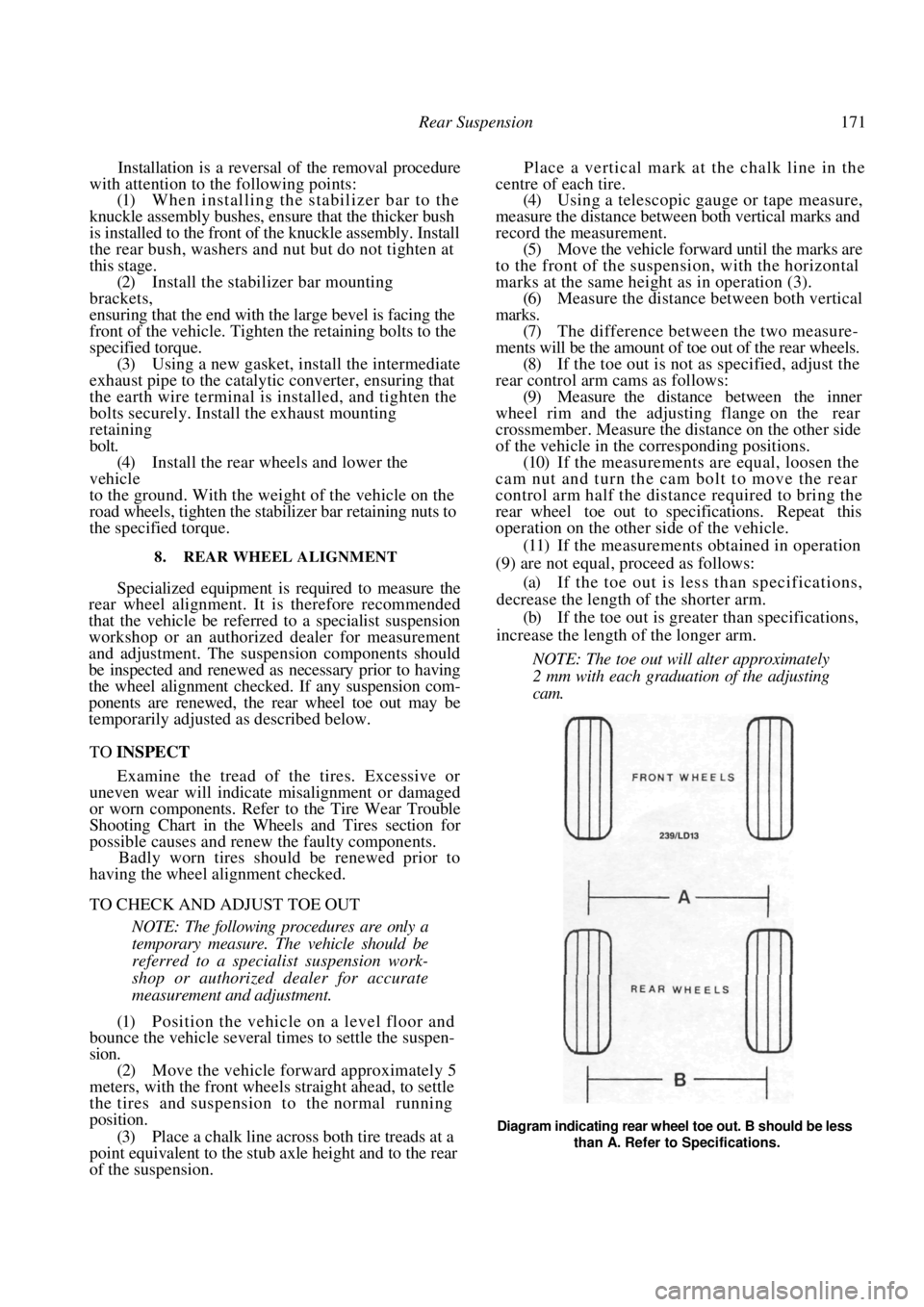
(3) Place a chalk line across both tire treads at a
point equivalent to the stub axle height and to the rear
of the suspension. Place a vertical mark at the chalk line in the
centre of each tire.
(4) Using a telescopic gauge or tape measure,
measure the distance between both vertical marks and
record the measurement. (5) Move the vehicle forward until the marks are
to the front of the suspen sion, with the horizontal
marks at the same height as in operation (3). (6) Measure the distance between both vertical
marks. (7) The difference between the two measure-
ments will be the amount of toe out of the rear wheels. (8) If the toe out is not as specified, adjust the
rear control arm cams as follows: (9) Measure the distance between the inner
wheel rim and the adjusting flange on the rear
crossmember. Measure the distance on the other side
of the vehicle in the corresponding positions. (10) If the measurements are equal, loosen the
cam nut and turn the cam bolt to move the rear
control arm half the distance required to bring the
rear wheel toe out to specifications. Repeat this
operation on the other side of the vehicle.
(11) If the measurements obtained in operation
(9) are not equal, proceed as follows:
(a) If the toe out is less than specifications,
decrease the length of the shorter arm.
(b) If the toe out is greater than specifications,
increase the length of the longer arm.
NOTE: The toe out will alter approximately
2 mm with each graduation of the adjusting
cam.
Diagram indicating rear wheel toe out. B should be less than A. Refer to Specifications.
Page 210 of 238
210 Electrical System
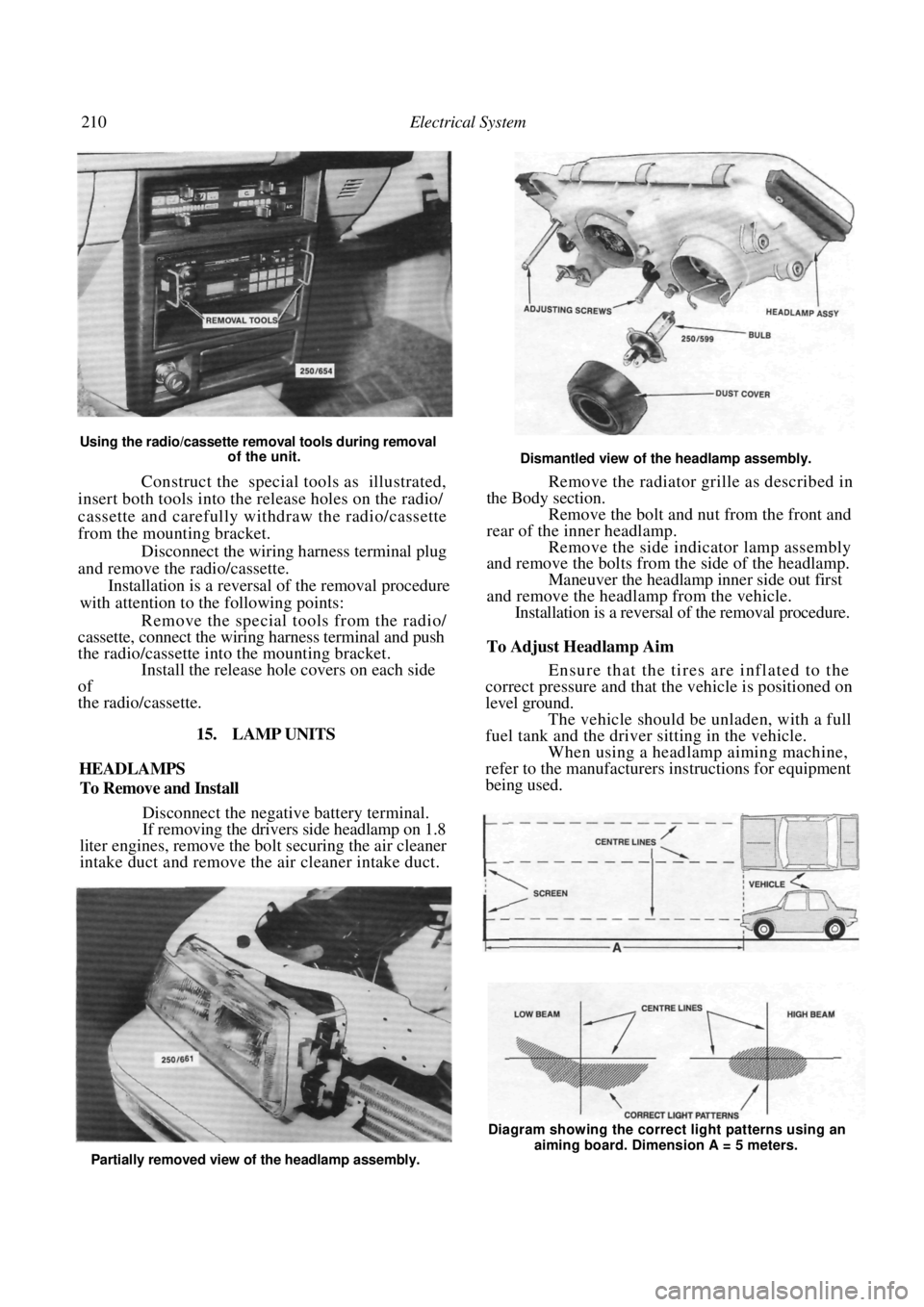
Using the radio/cassette removal tools during removal of the unit.
Construct the special tools as illustrated,
insert both tools into the release holes on the radio/
cassette and carefully withdraw the radio/cassette
from the mounting bracket.
Disconnect the wiring harness terminal plug
and remove the radio/cassette.
Installation is a reversal of the removal procedure
with attention to the following points:
Remove the special tools from the radio/
cassette, connect the wiring harness terminal and push
the radio/cassette into the mounting bracket. Install the release hole covers on each side
of
the radio/cassette.
15. LAMP UNITS
HEADLAMPS
To Remove and Install
Disconnect the negative battery terminal.
If removing the drivers side headlamp on 1.8
liter engines, remove the bo lt securing the air cleaner
intake duct and remove the air cleaner intake duct.
Dismantled view of the headlamp assembly.
Remove the radiator grille as described in
the Body section. Remove the bolt and nut from the front and
rear of the inner headlamp. Remove the side indicator lamp assembly
and remove the bolts from the side of the headlamp.
Maneuver the headlamp inner side out first
and remove the headlamp from the vehicle. Installation is a reversal of the removal procedure.
To Adjust Headlamp Aim
Ensure that the tires are inflated to the
correct pressure and that the vehicle is positioned on
level ground.
The vehicle should be unladen, with a full
fuel tank and the driver sitting in the vehicle. When using a headlamp aiming machine,
refer to the manufacturers instructions for equipment
being used.
Partially removed view of the headlamp assembly. Diagram showing the correct light patterns using an
aiming board. Dimension A = 5 meters.