reset NISSAN PULSAR 1987 Workshop Manual
[x] Cancel search | Manufacturer: NISSAN, Model Year: 1987, Model line: PULSAR, Model: NISSAN PULSAR 1987Pages: 238, PDF Size: 28.91 MB
Page 92 of 238

92 Fuel and Engine Management
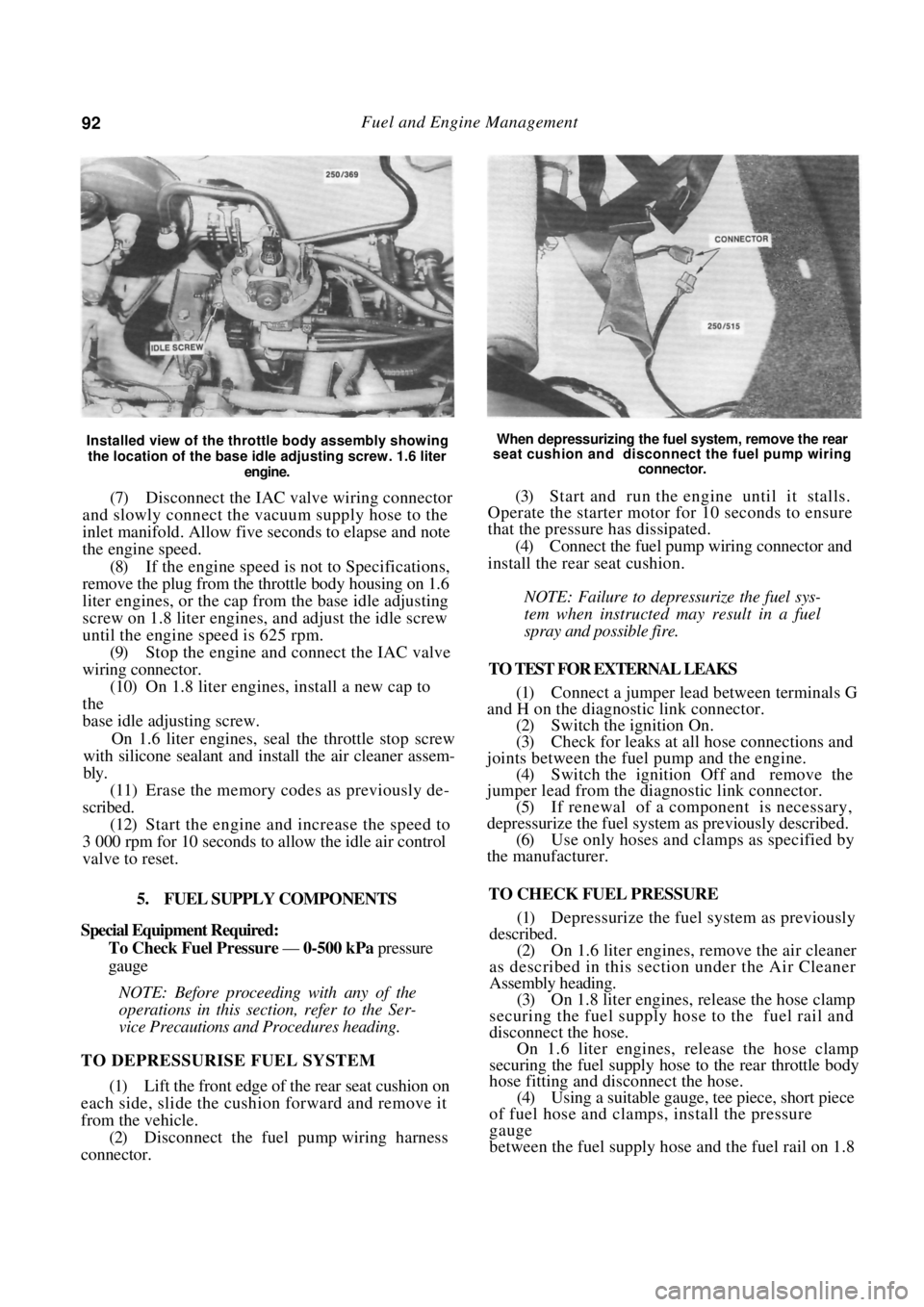
Installed view of the throttle body assembly showing
the location of the base idle adjusting screw. 1.6 liter
engine.
(7) Disconnect the IAC valve wiring connector
and slowly connect the vacuum supply hose to the
inlet manifold. Allow five seconds to elapse and note
the engine speed.
(8) If the engine speed is not to Specifications,
remove the plug from the throttle body housing on 1.6
liter engines, or the cap from the base idle adjusting
screw on 1.8 liter engines, and adjust the idle screw
until the engine speed is 625 rpm. (9) Stop the engine and connect the IAC valve
wiring connector. (10) On 1.8 liter engines, install a new cap to
the
base idle adjusting screw.
On 1.6 liter engines, seal the throttle stop screw
with silicone sealant and install the air cleaner assem-
bly.
(11) Erase the memory codes as previously de-
scribed.
(12) Start the engine and increase the speed to
3 000 rpm for 10 seconds to allow the idle air control
valve to reset.
5. FUEL SUPPLY COMPONENTS
Special Equipment Required:
To Check Fuel Pressure — 0-500 kPa pressure
gauge
NOTE: Before proceeding with any of the
operations in this section, refer to the Ser-
vice Precautions and Procedures heading.
TO DEPRESSURISE FUEL SYSTEM
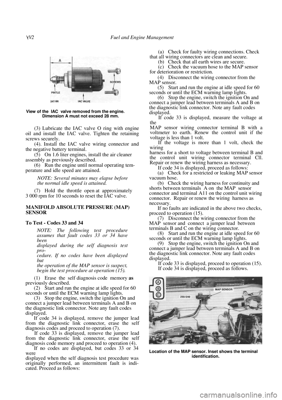
(1) Lift the front edge of the rear seat cushion on
each side, slide the cushion forward and remove it
from the vehicle. (2) Disconnect the fuel pump wiring harness
connector.
When depressurizing the fuel system, remove the rear
seat cushion and disconnect the fuel pump wiring
connector.
(3) Start and run the engine until it stalls.
Operate the starter motor for 10 seconds to ensure
that the pressure has dissipated.
(4) Connect the fuel pump wiring connector and
install the rear seat cushion.
NOTE: Failure to depressurize the fuel sys-
tem when instructed may result in a fuel
spray and possible fire.
TO TEST FOR EXTERNAL LEAKS
(1) Connect a jumper lead between terminals G
and H on the diagnostic link connector.
(2) Switch the ignition On.
(3) Check for leaks at all hose connections and
joints between the fuel pump and the engine. (4) Switch the ignition Off and remove the
jumper lead from the diagnostic link connector.
(5) If renewal of a component is necessary,
depressurize the fuel system as previously described. (6) Use only hoses and clamps as specified by
the manufacturer.
TO CHECK FUEL PRESSURE
(1) Depressurize the fuel system as previously
described. (2) On 1.6 liter engines, remove the air cleaner
as described in this section under the Air Cleaner
Assembly heading. (3) On 1.8 liter engines, release the hose clamp
securing the fuel supply hos e to the fuel rail and
disconnect the hose. On 1.6 liter engines, release the hose clamp
securing the fuel supply hose to the rear throttle body
hose fitting and disconnect the hose.
(4) Using a suitable gauge, tee piece, short piece
of fuel hose and clamps, install the pressure
gauge
between the fuel supply ho se and the fuel rail on 1.8
Page 102 of 238

\(V2 Fuel and Engine Management
View of the IAC valve removed from the engine. Dimension A must not exceed 28 mm.
(3) Lubricate the IAC valve O ring with engine
oil and install the IAC valve. Tighten the retaining
screws securely.
(4). Install the IAC valve wiring connector and
the negative battery terminal.
(5) On 1.6 liter engines, install the air cleaner
assembly as previously described. (6) Run the engine until normal operating tem-
perature and idle speed are attained.
NOTE: Several minutes may elapse before
the normal idle speed is attained.
(7) Hold the throttle open at approximately
3 000 rpm for 10 seconds to reset the IAC valve.
MANIFOLD ABSOLUTE PRESSURE (MAP)
SENSOR
To Test - Codes 33 and 34
NOTE: The following test procedure
assumes that fault codes 33 or 34 have
been
displayed during the self diagnosis test
pro-
cedure. If no codes have been displayed
but
the operation of the MAP sensor is suspect,
begin the test procedure at operation (15).
(1) Erase the self diagnosis code memory as
previously described.
(2) Start and run the engine at idle speed for 60
seconds or until the ECM warning lamp lights.
(3) Stop the engine, switch the ignition On and
connect a jumper lead between terminals A and B on
the diagnostic link connector. Note any fault codes
displayed. If code 34 is displayed, remove the jumper lead
from the diagnostic link connector, erase the self
diagnosis codes and proceed to operation (7).
If code 33 is displayed, remove the jumper lead
from the diagnostic link connector, erase the self
diagnosis code memory and proceed to operation (4).
If no codes are displayed, but codes 33 or 34
were
displayed when the self diagnosis test procedure was
originally performed, an intermittent fault is indi-
cated. Proceed as follows:
(a) Check for faulty wiring connections. Check
that all wiring connectors are clean and secure. (b) Check that all earth wires are secure.
(c) Check the vacuum hose to the MAP sensor
for deterioration or restriction.
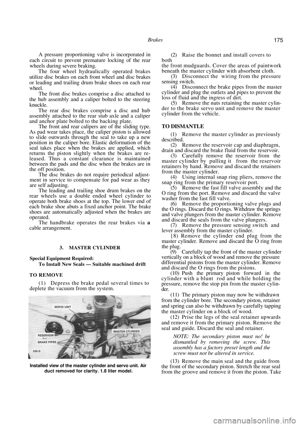
(4) Disconnect the wiring connector from the
MAP sensor. (5) Start and run the engine at idle speed for 60
seconds or until the ECM warning lamp lights. (6) Stop the engine, switch the ignition On and
connect a jumper lead between terminals A and B on
the diagnostic link connector. Note any fault codes
displayed.
If code 33 is displayed, measure the voltage at
the
MAP sensor wiring connector terminal B with a
voltmeter to earth. Renew the control unit if the
voltage is less than 1 volt.
If the voltage is more than 1 volt, check the
wiring
harness for a short to voltage between terminal B and
the control unit wiring connector terminal Cll.
Repair or renew the wiring harness as necessary.
If code 34 is displayed, proceed as follows:
(a) Check for a restricted or leaking MAP sensor
vacuum hose.
(b) Check the wiring harness for continuity and
shorts between terminals A on the MAP sensor
connector and terminal A11 on the control unit wiring
connector. Repair or renew the wiring harness as
necessary.
If no faults are indicated in the above two checks,
proceed to operation (15).
(7) Disconnect the wiring connector from the
MAP sensor and connect a jumper lead between
terminals B and C on the wiring connector. (8) Start and run the engine at idle speed for 60
seconds or until the ECM warning lamp lights. (9) Stop the engine, switch the ignition On and
connect a jumper lead between terminals A and B on
the diagnostic link connector. Note any fault codes
displayed.
If code 33 is displayed, proceed to operation (15).
If code 34 is displayed, proceed as follows.
Location of the MAP sensor. Inset shows the terminal
identification.
Page 175 of 238

Brakes 175
A pressure proportioning valve is incorporated in
each circuit to prevent premature locking of the rear
wheels during severe braking.
The four wheel hydraulically operated brakes
utilize disc brakes on each front wheel and disc brakes
or leading and trailing drum brake shoes on each rear
wheel.
The front disc brakes comprise a disc attached to
the hub assembly and a caliper bolted to the steering
knuckle.
The rear disc brakes comprise a disc and hub
assembly attached to the rear stub axle and a caliper
and anchor plate bolted to the backing plate.
The front and rear calipers are of the sliding type.
As pad wear takes place, the caliper piston is allowed
to slide outwards through the seal to take up a new
position in the caliper bore. Elastic deformation of the
seal takes place when the brakes are applied, which
returns the piston slightly when the brakes are re-
leased. Thus a constant clearance is maintained
between the pads and the disc when the brakes are in
the off position.
The disc brakes do not require periodical adjust-
ment in service to compensate for pad wear as they
are self adjusting.
The leading and trailing shoe drum brakes on the
rear wheels use a double ended wheel cylinder to
operate both brake shoes at the top. The lower end of
each brake shoe abuts a fixed anchor point. The brake
shoes are automatically adju sted when the brakes are
operated.
The handbrake operates the rear brakes via a
cable arrangement.
3. MASTER CYLINDER
Special Equipment Required:
To Install New Seals — Suitable machined drift
TO REMOVE
(1) Depress the brake pedal several times to
deplete the vacuum from the system.
(2) Raise the bonnet and install covers to
both
the front mudguards. Cover the areas of paintwork
beneath the master cylinder with absorbent cloth.
(3) Disconnect the wiring from the pressure
sensing switch. (4) Disconnect the brake pipes from the master
cylinder and plug the outlets and pipes to prevent the
loss of fluid and the ingress of dirt.
(5) Remove the nuts retaining the master cylin-
der to the brake servo unit and remove the master
cylinder from the vehicle.
TO DISMANTLE
(1) Remove the master cylinder as previously
described. (2) Remove the reservoir cap and diaphragm,
drain and discard the brake fluid from the reservoir. (3) Carefully remove the reservoir from the
master cylinder by pulling it from the reservoir
retainers by hand. Remove and discard the retainers
from the master cylinder. (4) Using internal snap ring pliers, remove the
snap ring from the primary reservoir port. (5) Remove the fast fill valve assembly and the
O ring from the port. Remove and discard the valve
washer from the fast fill valve.
(6) Remove the proportioning valve plugs and
the O rings. Discard the O rings. Withdraw the springs
and valve plungers from the master cylinder. Remove
and discard the seals from the valve plungers. (7) Remove the pressure sensing switch and
lever assembly from the master cylinder. {8) Remove the cylinder end plug from the
master cylinder. Remove and discard the O ring from
the plug.
(9) Carefully tap the front of the master cylinder
vertically on a block of wo od and remove the pressure
differential pistons from the master cylinder. Remove
and discard the O rings from the pistons. (10) Push the primary piston forward in the
cylinder with a blunt rod and while holding the
pressure, remove the stop pin from the master cylin-
der.
(11) The primary piston may now be withdrawn
from the cylinder bore. The secondary piston, retainer
and spring can also be withdrawn by carefully tapping
the master cylinder on a block of wood. (12) Prise the legs of the seal retainer upwards
and remove it from the primary piston. Remove the
seal and guide. Discard the seal and retainer.
NOTE: The secondary piston must no! be
dismantled by removing the screw. This
assembly has a factory p reset length and the
screw must not be altered in service.
(13) Remove the main seal and the guide from
the front of the secondary piston. Stretch the rear seal
from the groove and remove it from the piston. Take
Installed view of the master cylinder and servo unit. Air
duct removed for clarity. 1.8 liter model.