change wheel NISSAN PULSAR 1987 Workshop Manual
[x] Cancel search | Manufacturer: NISSAN, Model Year: 1987, Model line: PULSAR, Model: NISSAN PULSAR 1987Pages: 238, PDF Size: 28.91 MB
Page 3 of 238

CONTENTS
INTRODUCTION........................................ 5
VEHICLE IDENTIFICATION AND
GENERAL SPECIFICATIONS................. 7
GENERAL INFORMATION...................... 8
Tools and equipment ............................................. 8 Safety .................................................................... 10
General repair procedures..................................... 11
LUBRICATION AND MAINTENANCE... 14
Specifications......................................................... 14
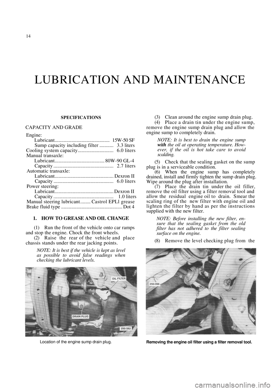
How to grease and oil change .............................. 14
Service schedule ................................................... 17
WHEELS AND TYRES............................. 21
Specifications......................................................... 21
How to change a road wheel ................................ 21
Tire wear troubl e shooting ..................................... 22
Care and main tenance ......................................... 23
ENGINE TUNE-UP.................................... 25
Tune-up specifications ........................................... 25
Tune-up operat ions............................................... 25
ROADSIDE TROUBLE SHOOTING....... 32
Trouble shoot ing.................................................... 32
To check ignition and el ectrical system ................ 33
To check fuel system ............................................ 34
To check mechani cal system ................................ 35
ENGINE....................................................... 37
Specifications ........................................................ 37
Engine mechanical tr ouble shooting ...................... 39
Description ............................................................ 41
Engine and transaxle assembly ........................... 42
Manifolds ............................................................... 44 Camshaft, rocker arms and tappets..................... 48
Cylinder head........................................................ 50
Engine sump and oil pum p pickup pipe................ 54
Oil pump ............................................................... 55
Pistons, connecting rods and cylinder bores ........ 57
Crankshaft and bearings ...................................... 60
Flywheel /drive plate............................................... 63
Engine mountings.................................................. 64
Exhaust system .................................................... 66
COOLING AND HEATING SYSTEMS.... 68
Specifications ........................................................ 68 Cooling system trouble shooting ........................... 68
Heater and air conditioner trouble shooting ......... 69 Description ............................................................ 70
Radiator ................................................................ 70
Cooling fan ............................................................ 73
Thermost at............................................................ 75
Thermostat housing .............................................. 76
Water pump .......................................................... 76
Welch plugs .......................................................... 76
Heater unit, water valv e and controls ................... 77
Blower fan ............................................................. 80
Air condition ing ..................................................... 80
FUEL AND ENGINE MANAGEMENT ... 82
Specifications ........................................................ 82 Fuel and engine management trouble shooting ... 82
Description ............................................................ 84
Service precautions and procedures
..................... 86
System diagnosis and adjustments ...................... 89
Fuel supply components ....................................... 92
Air flow components .............................................. 98
Electronic components .......................................... 104
EMISSION CONTROL............................. 117
Introduction ........................................................... 117
Crankcase ventilati on system............................... 117
Evaporate control system..................................... 117
Air preheat system — 1.6 liter engines ................ 119
Exhaust control system ........................................ 120
CLUTCH...................................................... 121
Specifications........................................................ 121
Clutch trouble shooting......................................... 121
Description ............................................................ 122
Clutch unit and release mechanism..................... 123
Clutch pedal ......................................................... 124
Clutch c able.......................................................... 124
Clutch adjustments ............................................... 125
MANUAL TRANSAXLE AND
DRIVE SHAFTS......................................... 126
Specifications ........................................................ 126
Manual transaxle and drive shaft trouble shooting 126
Description............................................................ 128
Transaxle assembly.............................................. 129
Differential and final drive assembly ..................... 135
Gear lever assembly ............................................ 136
Drive shafts .......................................................... 137
AUTOMATIC TRANSAXLE....................... 140
Specifications........................................................ 140
Automatic transaxle trouble shooting.................... 140
Description............................................................ 141
Transaxle fluid ...................................................... 141
Brake band........................................................... 142
Kickdown cable .................................................... 142
Transaxle select or linkage ................................... 142
Neutral safety switch ............................................ 142
Transaxle assembly .............................................. 143
STEERING................................................. 145
PART 1. STEERING TROUBLE SHOOTING....145
Faults, causes and remedies................................ 145
PART 2. MANUA L STEERING......................... 147
Specifications ........................................................ 147
Description............................................................ 147
Steering wheel ...................................................... 147
Steering column.................................................... 148
Steering gear assembly ....................................... 149
PART 3. POWE R STEERING .......................... 152
Specifications........................................................ 152
Description............................................................ 152
In car adjustments, checks and minor repairs ..... 152
Steering wheel ...................................................... 153
Steering column.................................................... 153 Power steering pump ........................................... 153
Power steering gear assembly............................. 154
Page 14 of 238

14
LUBRICATION AND MAINTENANCE
SPECIFICATIONS
CAPACITY AND GRADE
Engine:
Lubricant........................................... 15W-50 SF
Sump capacity including filter ........... 3.3 liters
Cooling system capacity............................ 6.0 liters
Manual transaxle:
Lubricant....................................... 80W-90 GL-4
Capacity ............................................... 2.7 liters
Automatic transaxle:
Lubricant.............................................. Dexron II
Capacity ............................................... 6.0 liters
Power steering:
Lubricant.............................................. Dexron II
Capacity ............................................... 1.0 liters
Manual steering lubricant ........ Castrol EPLl grease
Brake fluid type ................................................ Dot 4
1. HOW TO GREASE AND OIL CHANGE
(1) Run the front of the vehicle onto car ramps
and stop the engine. Chock the front wheels. (2) Raise the rear of the vehicle and place
chassis stands under the rear jacking points.
NOTE: It is best if the vehicle is kept as level
as possible to avoi d false readings when
checking the lubricant levels.
(3) Clean around the engine sump drain plug.
(4) Place a drain tin under the engine sump,
remove the engine sump drain plug and allow the
engine sump to completely drain.
NOTE: It is best to drain the engine sump
with the oil at operating temperature. How-
ever, if the oil is hot take care to avoid
scalding.
(5) Check that the sealing gasket on the sump
plug is in a serviceable condition. (6) When the engine sump has completely
drained, install and firmly tighten the sump drain plug.
Wipe around the plug after installation. (7) Place the drain tin under the oil filler,
remove the oil filter using a filter removal tool and
allow the residual engine oil to drain. Smear the
scaling ring of the new filter with engine oil and
lighten the filter by hand as per the instructions
supplied with the new filter.
NOTE: Before installing the new filter, en-
sure that the sealing gasket from the old
filter has not adhered to the filter sealing
surface on the engine.
(8) Remove the level checking plug from the
Location of the engine sump drain plug.
Removing the engine oil filter using a filter removal tool.
Page 21 of 238

WHEELS AND TYRES
SPECIFICATIONS
TYRES PRESSURES
Front:
Normal load ............................................ 200 kPa
Heavy load or high speed ......................230 kPa
Rear:
Normal load............................................ 180 kPa
Heavy load or high speed ...................... 210 kPa
NOTE: The above pressures are measured
cold and are meant as a guide only. Always
refer to the tire placard positioned on the
inside of the glove compartment lid and the
tire manufacturers recommendations first.
TORQUE WRENCH SETTINGS
Wheel nut torque .............................................98 Nm
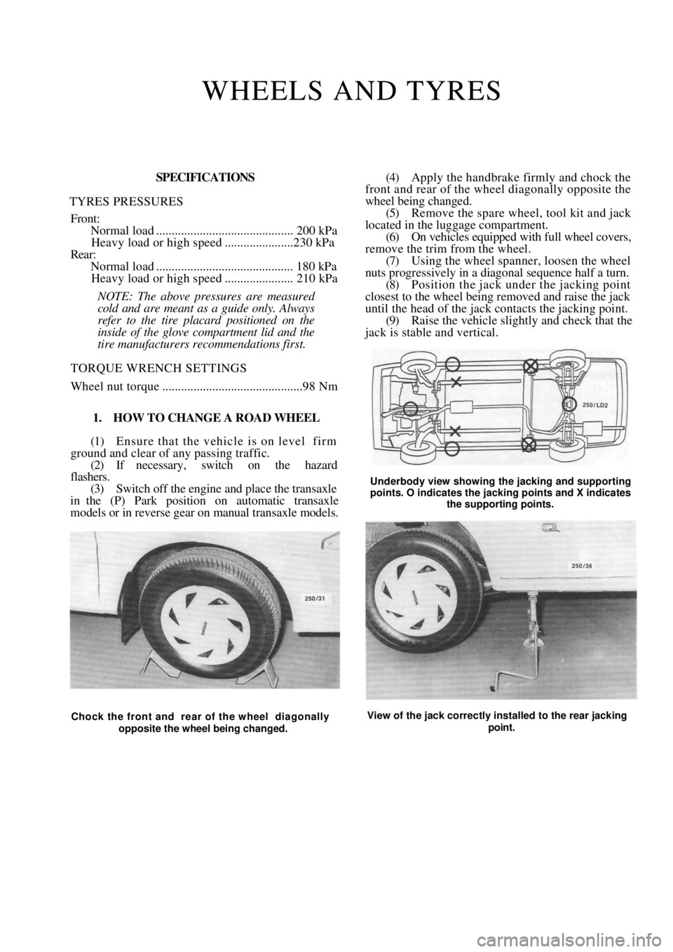
1. HOW TO CHANGE A ROAD WHEEL
(1) Ensure that the vehicle is on level firm
ground and clear of any passing traffic. (2) If necessary, switch on the hazard
flashers.
(3) Switch off the engine a nd place the transaxle
in the (P) Park position on automatic transaxle
models or in reverse gear on manual transaxle models.
(4) Apply the handbrake firmly and chock the
front and rear of the wheel diagonally opposite the
wheel being changed.
(5) Remove the spare wheel, tool kit and jack
located in the luggage compartment. (6) On vehicles equipped with full wheel covers,
remove the trim from the wheel. (7) Using the wheel spanner, loosen the wheel
nuts progressively in a diagonal sequence half a turn.
(8) Position the jack und er the jacking point
closest to the wheel being removed and raise the jack
until the head of the jack contacts the jacking point.
(9) Raise the vehicle slightly and check that the
jack is stable and vertical.
Underbody view showing the jacking and supporting
points. O indicates the jacking points and X indicates
the supporting points.
Chock the front and rear of the wheel diagonally
opposite the wheel being changed. View of the jack correctly installed to the rear jacking
point.
Page 24 of 238

24 Wheels and Tires
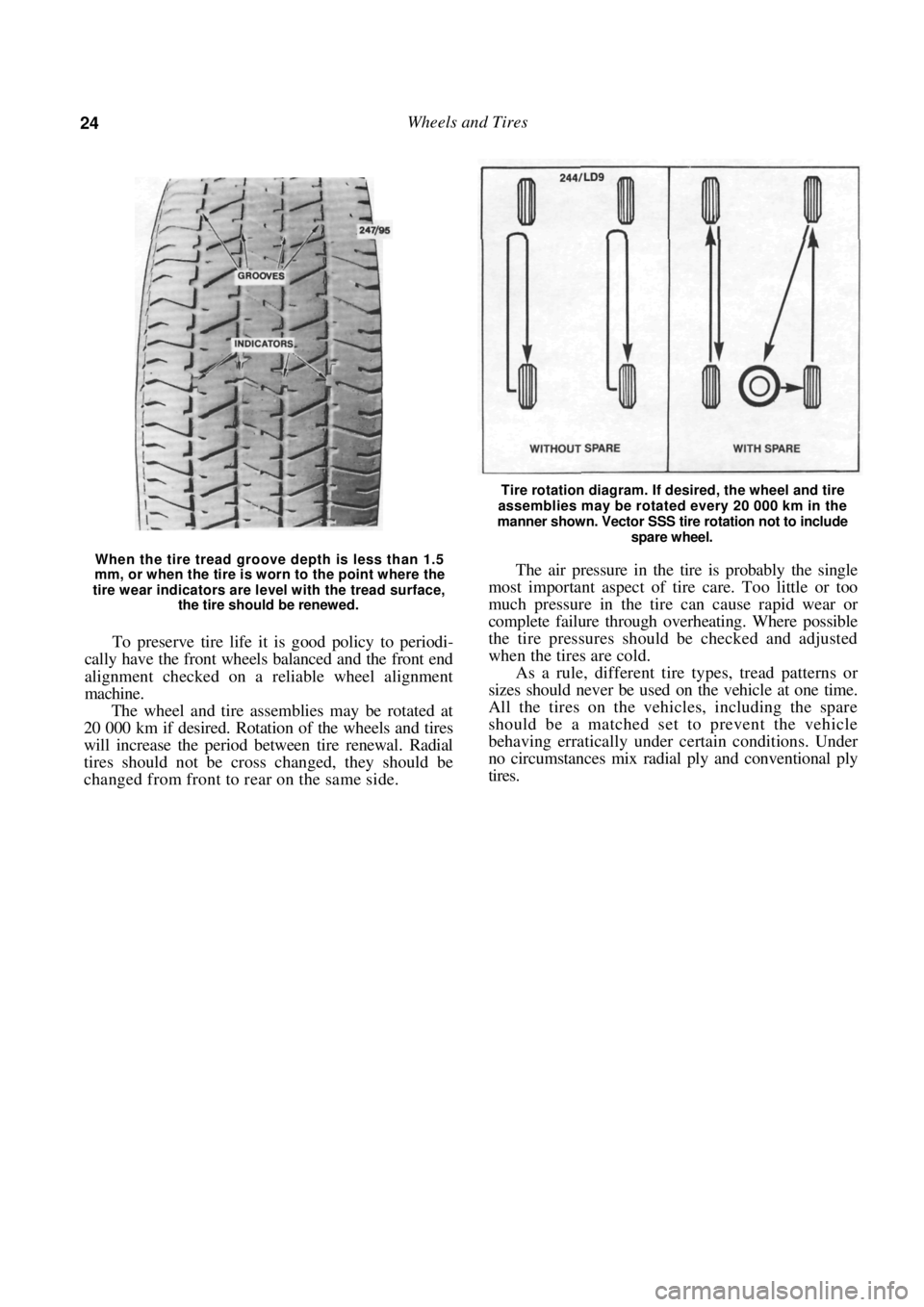
When the tire tread groove depth is less than 1.5
mm, or when the tire is worn to the point where the
tire wear indicators are level with the tread surface,
the tire should be renewed.
To preserve tire life it is good policy to periodi-
cally have the front wheels balanced and the front end
alignment checked on a reliable wheel alignment
machine.
The wheel and tire assemblies may be rotated at
20 000 km if desired. Rotation of the wheels and tires
will increase the period between tire renewal. Radial
tires should not be cross changed, they should be
changed from front to rear on the same side.
Tire rotation diagram. If desired, the wheel and tire
assemblies may be rotated every 20 000 km in the
manner shown. Vector SSS tire rotation not to include
spare wheel.
The air pressure in the tire is probably the single
most important aspect of tire care. Too little or too
much pressure in the tire can cause rapid wear or
complete failure through overheating. Where possible
the tire pressures should be checked and adjusted
when the tires are cold.
As a rule, different tire types, tread patterns or
sizes should never be used on the vehicle at one time.
All the tires on the vehicles, including the spare
should be a matched set to prevent the vehicle
behaving erratically under certain conditions. Under
no circumstances mix radial ply and conventional ply
tires.
Page 41 of 238

Engine 41
DROP IN OIL PRESSURE
(1) Oil level low in the sump: Check and replen-
ish the oil to the full mark on the dipstick.
(2) Thin or diluted oil: Change to the correct oil
grade and rectify the source of dilution. (3) Oil pump relief valve stuck or spring broken;
Free up the relief valve or renew the broken relief
valve spring. (4) Excessive bearing clearance: Renew the bear-
ing shells or recondition the crankshaft journals as
necessary.
(5) Excessive wear of the oil pump components:
Renew or recondition the oil pump.
NOTE: If the vehicle is not equipped with an
oil pressure gauge re move the oil sender unit
and connect a pressure gauge into the oil
gallery. Check the oil pressure with the
engine cold and hot. If the oil pump or relief
valve are faulty. low pressure will be indi-
cated with the engine both hot and cold.
However, if the bearings are at fault a fairly
high oil pressure will be indicated when the
engine is cold, but a marked drop in pressure
will occur when the engine is hot.
ENGINE WILL NOT ROTATE
(1) Starter motor drive jammed: Remove the
starter motor. Check and renew the damaged drive
and/or flywheel ring gear.
(2) Engine overheated an d seized: Remove and
dismantle the engine. Check and renew any damaged
components. See the following note.
(3) Water in the cylinder due to a blown head
gasket or cracked cylinder block or head: Remove the
cylinder head. If the gasket is blown, check for
cylinder block and head distortion and reface if
necessary. Renew the cylinder head and/or cylinder
block if cracked.
(4) Broken crankshaft, connecting rod. piston
etc. due to overheating, fatigue etc: Remove and
dismantle the engine. Examine and renew any com-
ponents as necessary. (5) Valve head broken off due to overheating,
fatigue etc: Remove the cylinder head and check the
head, piston and cylinder bore for damage. Repair or
renew as necessary.
NOTE: Invariably when an engine seizes
because of overheating due to lack of oil
and/or water, damage is done to the bear-
ings, pistons etc. Although there may be
instances where an engine will start and run
after it has cooled down and the oil and
water have been replenished, it will usually
be found that oil consumption increases, oil
pressure decreases and the engine will be
noisier, depending on the degree of damage.
When a cylinder head gasket blows allow-
ing water into the cylinders, or compression
loss between the cylinders, it is essential to
check the gasket faces on the cylinder block
and head for distortion. Sufficient water can
enter a cylinder because of a blown head
gasket, cracked cylinder or head to prevent
an engine from rotating.
This is normally preceded by difficult
starting, misfiring, excessive steam from the
exhaust and loss of water from the radiator.
Frequent jamming of the starter motor
drive with the flywheel ring gear can be due
to a bent starter armature shaft or damaged
teeth on the drive and/or ring gear. With the
starter motor removed, the flywheel ring
gear teeth can be examined through the
starter motor mounting aperture. Renewal
of the ring gear requires removal of the
transaxle, clutch and flywheel on manual
transaxle models and the removal of the
transaxle and drive plate on automatic
transaxle models. To check for a bent arma-
ture shaft, rotate the shaft by hand while
holding the end in close proximity to a fixed
object.
2. DESCRIPTION
The 1.6 and 1.8 liter engines are basically identi-
cal in design.
Both engines share the same stroke. The 1.8 liter
engine has a larger bore thus giving it increased
capacity.
The engine is a four cylinder, inline, overhead
camshaft design transversely mounted in the front of
the vehicle.
The camshaft runs in five integral support bear-
ings in the camshaft housing which in turn is mounted
directly on to the cylinder head and retained by the
cylinder head bolts.
Camshaft end float is controlled by a retaining
plate engaged in a groove machined in the rear
camshaft journal. The camshaft is driven by the
crankshaft timing gear vi a a reinforced rubber belt.
The aluminum cross flow cylinder head houses
the tappets, rocker arms a nd valve assemblies. An oil
pressure relief valve is installed to the cylinder head to
maintain oil pressure to the hydraulic tappets at a
predetermined setting.
The exhaust valve springs are equipped with
rotators mounted below the valve springs which rotate
the exhaust valve assemblies. The rocker arms pivot
on hydraulic tappet assemblies and locate in notched
lash pads mounted on the valve stems. The camshaft
lobes bear directly onto the rocker arms and due to
the characteristics of the hydraulic tappet assemblies,
no provision is made for tappet clearance adjustment.
Page 188 of 238

188 Brakes
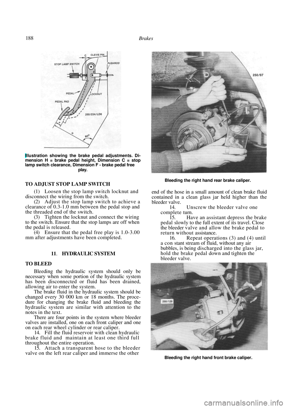
Illustration showing the brake pedal adjustments. Di-
mension H = brake pedal height, Dimension C = stop
lamp switch clearance, Dimension F - brake pedal free
play.
TO ADJUST STOP LAMP SWITCH
(1) Loosen the stop lamp switch locknut and
disconnect the wiring from the switch.
(2) Adjust the stop lamp switch to achieve a
clearance of 0.3-1.0 mm between the pedal stop and
the threaded end of the switch. (3) Tighten the locknut and connect the wiring
to the switch. Ensure that the stop lamps are off when
the pedal is released.
(4) Ensure that the pedal free play is 1.0-3.00
mm after adjustments have been completed.
11. HYDRAULIC SYSTEM
TO BLEED
Bleeding the hydraulic system should only be
necessary when some portion of the hydraulic system
has been disconnected or fluid has been drained,
allowing air to enter the system.
The brake fluid in the hydraulic system should be
changed every 30 000 km or 18 months. The proce-
dure for changing the brake fluid and bleeding the
hydraulic system are simila r with attention to the
notes in the text.
There are four points in the system where bleeder
valves are installed, one on each front caliper and one
on each rear wheel cylinder or rear caliper.
14. Fill the fluid reservoir with clean hydraulic
brake fluid and maintain at least one third full
throughout the entire operation. 15. Attach a transparent hose to the bleeder
valve on the left rear cali per and immerse the other
Bleeding the right hand rear brake caliper.
end of the hose in a small amount of clean brake fluid
contained in a clean glass jar held higher than the
bleeder valve.
14. Unscrew the bleeder valve one
complete turn.
15. Have an assistant depress the brake
pedal slowly to the full extent of its travel. Close
the bleeder valve and allow the brake pedal to
r e t u r n w i t h o u t assistance. 16. Repeat operations (3) and (4) until
a con stant stream of fluid, without any air
bubbles, is being discharged into the gl ass jar,
hold the brake pedal down and tighten the
bleeder valve.
Bleeding the right hand front brake caliper.