width NISSAN PULSAR 1987 Workshop Manual
[x] Cancel search | Manufacturer: NISSAN, Model Year: 1987, Model line: PULSAR, Model: NISSAN PULSAR 1987Pages: 238, PDF Size: 28.91 MB
Page 7 of 238
VEHICLE IDENTIFICATION AND GENERAL SPECIFICATIONS
1. VEHICLE IDENTIFICATION
When purchasing spare parts or when
registering
or insuring a vehicle, it may be necessary to quote
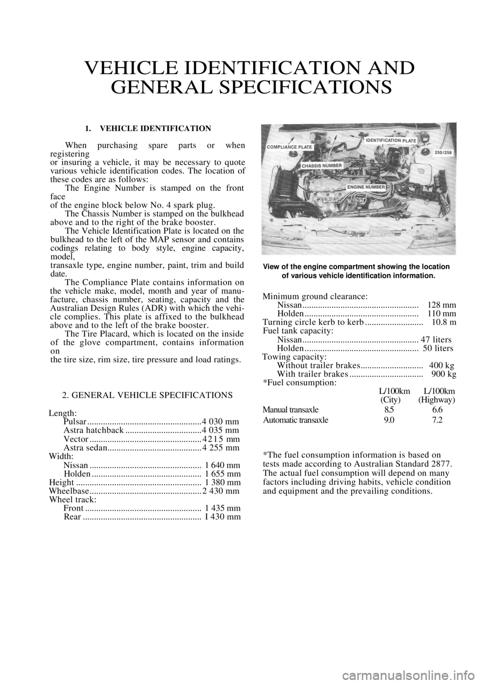
various vehicle identification codes. The location of
these codes are as follows: The Engine Number is stamped on the front
face
of the engine block below No. 4 spark plug. The Chassis Number is stamped on the bulkhead
above and to the right of the brake booster. The Vehicle Identification Plate is located on the
bulkhead to the left of the MAP sensor and contains
codings relating to body style, engine capacity,
model,
transaxle type, engine number, paint, trim and build
date. The Compliance Plate contains information on
the vehicle make, model, month and year of manu-
facture, chassis number, seating, capacity and the
Australian Design Rules (ADR) with which the vehi-
cle complies. This plate is affixed to the bulkhead
above and to the left of the brake booster. The Tire Placard, which is located on the inside
of the glove compartment, contains information
on
the tire size, rim size, tire pressure and load ratings.
2. GENERAL VEHICLE SPECIFICATIONS
Length:
Pulsar ................................................... 4 030 mm
Astra hatchback .................................. 4 035 mm
Vector ..................................................4215 mm
Astra sedan.......................................... 4 255 mm
Width:
Nissan.................................................. 1 640 mm
Holden ................................................. 1 655 mm
Height ........................................................ 1 380 mm
Wheelbase .................................................. 2 430 mm
Wheel track:
Front .................................................... 1 435 mm
Rear ..................................................... I 430 mm
View of the engine compartment showing the location
of various vehicle identification information.
Minimum ground clearance:
Nissan.................................................... 128 mm
Holden ................................................... 110 mm
Turning circle kerb to kerb .......................... 10.8 m
Fuel tank capacity:
Nissan.................................................... 47 liters
Holden ................................................... 50 liters
Towing capacity:
Without trailer brakes............................ 400 kg
With trailer brakes ................................. 900 kg
*Fuel consumption:
L/100km L/100km
(City) (Highway)
Manual transaxle 8.5 6.6
Automatic transaxle 9.0 7.2
*The fuel consumption information is based on
tests made according to Australian Standard 2877.
The actual fuel consumption will depend on many
factors including driving habits, vehicle condition
and equipment and the prevailing conditions.
Page 37 of 238
37
ENGINE
SPECIFICATIONS
ENGINE ASSEMBLY
Type........................................................... 4cyl OHC
Models ............................................. 1.6 liter, 1.8 liter
Capacity:
1.6 liter ................................................... 1 598 cc
1.8 liter ................................................... 1 796 cc
Firing order ...................................................... 1 -3-4-2
Bore:
1.6 liter.................................................. 80.0 mm
1.8 liter.................................................. 84.8 mm
Stroke ........................................................... 79.5 mm
Maximum compression pressure
variation between cylinders ......................... 100 kPa
NOTE: Specifications re garding engine tun-
ing arc listed in the Engine Tune-up section.
CYLINDER BLOCK
Type......................................................... 4 cyl in line
Material ........................................................ Cast iron
Bore diameter:
1.6 liter ............... 79. 995-80.065 in three groups
1.8 liter .................84. 755-84.905 in four groups
Bore taper limit ......................................... 0. 013 mm
Bore ovality limit ..................................... 0.013 mm
Block face distortion limit .......................... 0.10 mm
Maximum height of piston above block
face at top dead centre:
1.6 liter.................................................. 0.00 mm
1.8 liter.................................................. 0.50 mm
Bore oversize................................................ 0.50 mm
CYLINDER HEAD
Type........................................... One piece, cross flow
Material ............................................ Aluminum alloy
Distortion limit .......................................... 0.025 mm
Machining li mit ........................................... 0.25 mm
Minimum overall height after machining:
1.6 liter .................................................95.50 mm
1.8 liter .................................................94.80 mm
Valve seat angle ..........................................45 degrees
Valve seat contact width:
Inlet................................................... 1.0-1.5 mm
Exhaust ............................................. 1.7-2.2 mm
Valve stem protrusion ................. 18.4 mm from top
of cylinder head
Valve guide height .......... 12.2-12.5 mm from top of
cylinder head
VALVES AND SPRINGS
Valve length .............................................. 104. 2 mm
Valve head diameter:
1.6 liter —
Inlet........................................................ 36.0 mm
Exhaust .................................................. 32.0 mm
1.8 liter -
Inlet....................................................... 41.8 mm
Exhaust ................................................. 36.5 mm
Valve stem diameter:
Inlet...........................................6. 998-7.012 mm
Exhaust .....................................6.978-6.992 mm
Valve stem to guide clearance:
Inlet...........................................0.018-0.052 mm
Exhaust .....................................0.038-0.072 mm
Oversize valve system availability......... 0.075, 0.150
and 0.250 mm
Valve face angle ......................................... 44 degrees
Valve spring tension:
Valve closed .......................... 300 N at 37.5 mm
Valve open............................. 765 N at 26.5 mm
TAPPETS
Type .............................................................Hydraulic
Operating length ........................................ 63.26 mm
Diameter ....................................... 21.392-21.405mm
Leak down rate ............. 2-10 sec onds for 3.175 mm
PISTONS AND GUDGEON PINS
Piston type ....................................... Aluminum alloy
Diameter:
1.6 liter ........ 79. 955-80.035 mm in 8 categories
in increments of 0.01 mm
1.8 liter .......84.725-84.885 mm in 16 categories
in increments of 0.01 mm
Page 53 of 238
Engine 53
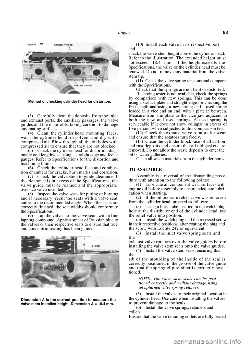
Method of checking cylinder head for distortion.
(3) Carefully clean the deposits from the inlet
and exhaust ports, the auxiliary passages, the valve
guides and the manifolds, taking care not to damage
any mating surfaces. (4) Clean the cylinder head mounting faces,
wash the cylinder head in solvent and dry with
compressed air. Blow through all the oil holes with
compressed air to ensure that they are not blocked. (5) Check the cylinder head for distortion diag-
onally and lengthwise using a straight edge and feeler
gauges. Refer to Specifications for the distortion and
machining limits. (6) Check the cylinder head face and combus-
tion chambers for cracks, burn marks and corrosion. (7) Check the valve stem to guide clearance. If
the clearance is in excess of the Specifications, the
valve guide must be reamed and the appropriate
oversize valve installed. (8) Inspect the valve seats for pitting or burning
and if necessary, recut the seats with a valve seat
cutter to the recommended angle. When the seats are
correctly finished, the seat widths should conform to
the Specifications. (9) Lap the valves to the valve seats with a fine
lapping compound. Apply a smear of Prussian blue to
the valves or their respective seats to ensure that true
and concentric seating has been gained.
(10) Install each valve in its respective port
and
check the valve stem height above the cylinder head.
Refer to the illustration. The extended height must
not exceed 18.4 mm. If the height exceeds the
Specifications, the valve or the cylinder head must be
renewed. Do not remove any material from the valve
stem tip.
(11) Check the valve spring tensions and compare
with the Specifications.
Check that the springs are not bent or distorted.
If a spring tester is not available, check the springs
by comparison with new springs. This can be done
using a surface plate and stra ight edge for checking the
free length and using a new spring and a used spring
loaded in a vice end on end, with a plate in between.
Measure from the plate to the vice jaw adjacent to
both the new and used springs. A used spring is
serviceable if it does not show collapse in excess of
five percent when subjected to this comparison test.
(12) Check the exhaust valve rotators for wear
and ensure that the rotators turn freely. (13) Clean the cylinder block face of all carbon
and rust deposits and ensure that all old gaskets are
removed. Do not allow the waste deposits to enter the
oil or water galleries. Clean all waste materials from the cylinder bores.
TO ASSEMBLE
Assembly is a reversal of the dismantling proce-
dure with attention to the following points:
(1) Lubricate all component wear surfaces with
engine oil before assembly to ensure adequate lubri-
cation when starting. (2) If the oil pressure relief valve was removed
from the cylinder head, proceed as follows:
(a) Using a brass tube inserted in the welch plug
hole at the distributor end of the cylinder head, tap
the relief valve into position. (b) Install the welch plug and the recessed screw
in their respective positions, after coating the plug and
the screw with Loctite 242 or equivalent.
(3) Install the inlet valve spring seats and
the
exhaust valve rotators over the valve guides before
installing the valve stem seals onto the valve guides.
(4) Install the valve stem seals, ensuring that
the
rib of the moulding on the inside of the seal is
correctly positioned in the groove of the valve guide
and that the spring clip retainer is correctly posi-
tioned.
NOTE: The valve stem seals can be posi-
tioned correctly and without damage using
an upturned valve spring retainer.
(5) Install the valves to their original location in
the cylinder head. Use care when installing the valves
to prevent damage to the seals.
(6) Install the valve springs, retainers and
collets.
Ensure that the valve retain ing collets are fully seated
Dimension A is the correct position to measure the
valve stem installed height. Dimension A = 18.4 mm.
Page 57 of 238
Engine 57
(23) Lower the vehicle to the ground and securely
tighten the wheel nuts.
10. PISTONS, CONNECTING RODS AND
CYLINDER BORES
Special Equipment Required:
To Inspect — Micrometer, cylinder measuring
gauge
To Remove Ridge from Bores — Ridge removal tool
To Deglaze Cylinder Bores — Cylinder surfacing
hone
To Install — Piston ring compressor
TO REMOVE
(1) Remove the engine sump and oil pump
pickup pipe as previously described. (2) Remove the cylinder head as previously
described. (3) Mark the relationship of the pistons to their
respective cylinders and the bearing caps to their
respective connecting rods by letter stamps or centre
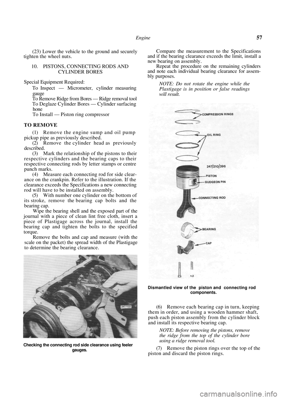
punch marks. (4) Measure each connecting rod for side clear-
ance on the crankpin. Refer to the illustration. If the
clearance exceeds the Speci fications a new connecting
rod will have to be installed on assembly. (5) With number one cylinder on the bottom of
its stroke, remove the bear ing cap bolts and the
bearing cap. Wipe the bearing shell and the exposed part of the
journal with a piece of clean lint free cloth, insert a
piece of Plastigage across the journal, install the
bearing cap and tighten the bolts to the specified
torque.
Remove the bolts and cap and measure (with the
scale on the packet) the spread width of the Plastigage
to determine the bearing clearance.
Compare the measurement to the Specifications
and if the bearing clearance exceeds the limit, install a
new bearing on assembly.
Repeat the procedure on the remaining cylinders
and note each individual bearing clearance for assem-
bly purposes.
NOTE: Do not rotate the engine while the
Plastigage is in position or false readings
will result.
Dismantled view of the piston and connecting rod
components.
(6) Remove each bearing cap in turn, keeping
them in order, and using a wooden hammer shaft,
push each piston assembly from the cylinder block
and install its respective bearing cap.
NOTE: Before removing the pistons, remove
the ridge from the top of the cylinder bore
using a ridge removal tool.
(7) Remove the piston rings over the top of the
piston and discard the piston rings.
Checking the connecting rod side clearance using feeler
gauges.
Page 61 of 238
Engine 61
rear main bearing cap and engine block. Discard the
oil seal.
(3) Ensure that all main bearing and connecting
rod bearing caps are numbered to ensure correct
assembly. (4) Remove the connecting rod bolts and caps,
keeping them in order. Push each piston and connect-
ing rod slightly up into the bore without pushing the
piston beyond its upper limit. (5) Check the crankshaft end float by inserting a
feeler gauge between the shaft and the centre main
bearing, or by mounting a dial gauge with its plunger
against one end of the shaft. (6) Push the crankshaft into contact with the
front edge of the centre main bearing, then lever the
shaft forward to determine the end float.
(7) If the end float exceeds the Specifications,
renew the centre main bearing on assembly. (8) Check the main bearing clearance by the
Plastigage method as follows:
(a) Remove one bearing cap and with a piece of
rag wipe the journal and bearing clean.
(b) Position a piece of Plastigage, the approxi-
mate length of the bearing width and slightly off
centre, on the bearing surface of the crankshaft
journal. (c) Install the bearing ca p and tighten the cap
bolts to the specified torque.
NOTE: Do not rotate the crankshaft while
the Plastigage is in position.
(d) Remove the cap bolts and carefully detach
the cap and lower half bearing. (e) With the Plastigage scal e, measure the com-
pressed Plastigage strip to determine the clearance. (f) The widest point of the strip will indicate the
minimum clearance and th e narrowest point the
maximum clearance. (g) The remaining bearings can be checked in
turn using the same procedure.
(9) Lift the crankshaft from the crankcase using
care not to dislodge or damage the upper halves of the
main bearing shells if they are to be used again. (10) If new bearing shells are to be installed,
remove the upper halves of the bearings from the
crankcase.
TO CHECK AND INSPECT
After thoroughly cleaning the crankshaft in sol-
vent and drying it with co mpressed air, blow out all
the oilways and make the following checks:
(1) Check and measure the main bearing jour-
nals and crankpins for wear, taper and scoring. If wear
is excessive, the journals and/or crankpins should be
ground to accommodate the nearest underside bearing
shells.
One worn or damaged journal or crankpin will
necessitate the grinding of all the journals or crank-
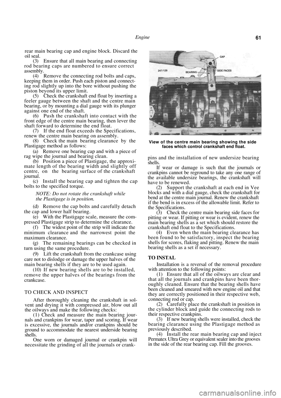
View of the centre main bearing showing the side
faces which control crankshaft end float.
pins and the installation of new undersize bearing
shells.
If wear or damage is such that the journals or
crankpins cannot be reground to take any one range of
the available undersize bearings, the crankshaft will
have to be renewed.
(2) Support the crankshaft at each end in Vee
blocks and with a dial gauge, check the crankshaft for
bend at the centre main jour nal. Renew the crankshaft
if the bend is in excess of the allowable limit. Refer to
the Specifications.
(3) Check the centre main bearing side faces for
pitting or wear. If pitting or wear is evident, renew the
main bearing shells as a set which should restore the
crankshaft end float to the Specifications. (4) Even when the main bearing clearance has
been found to be satisfact ory, inspect the bearing
shells for scores, flaking and pitting. Renew the main
bearing shells as a set if necessary.
TO INSTAL
Installation is a reversal of the removal procedure
with attention to the following points:
(1) Ensure that all of the oilways are clear and
that all the journals and crankpins have been thor-
oughly cleaned. Ensure that the bearing shells have
been cleaned and smeared with new engine oil and that
they are correctly positioned in their respective web,
connecting rod or cap. (2) Carefully place the crankshaft in position in
the cylinder block and guide the connecting rods to
their respective crankpins.
(3) If new bearing shells were installed, check the
bearing clearance using the Plastigage method as
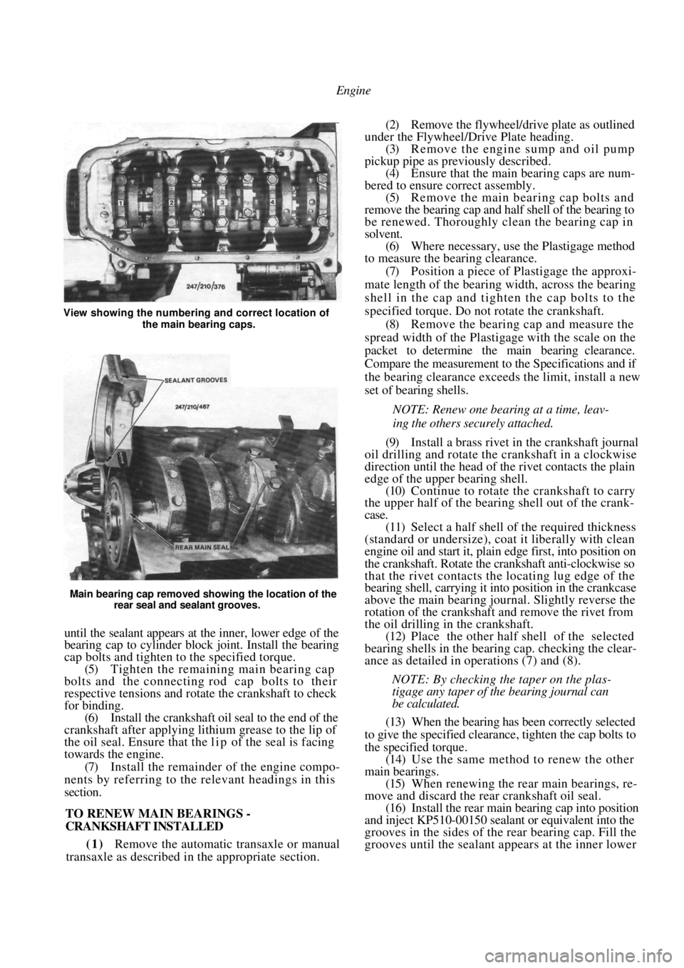
previously described. (4) Install the rear main bearing cap and inject
Permatex Ultra Grey or equivalent sealer into the grooves
in the side of the rear bearing cap. Fill the grooves.
Page 62 of 238
Engine
Main bearing cap removed showing the location of the rear seal and sealant grooves.
until the sealant appears at the inner, lower edge of the
bearing cap to cylinder block joint. Install the bearing
cap bolts and tighten to the specified torque.
(5) Tighten the remaining main bearing cap
bolts and the connecting rod cap bolts to their
respective tensions and rotate the crankshaft to check
for binding. (6) Install the crankshaft oil seal to the end of the
crankshaft after applying lithium grease to the lip of
the oil seal. Ensure that the l i p of the seal is facing
towards the engine.
(7) Install the remainder of the engine compo-
nents by referring to the relevant headings in this
section.
TO RENEW MAIN BEARINGS -
CRANKSHAFT INSTALLED
(1) Remove the automatic transaxle or manual
transaxle as described in the appropriate section.
(2) Remove the flywheel/drive plate as outlined
under the Flywheel/Drive Plate heading. (3) Remove the engine sump and oil pump
pickup pipe as previously described. (4) Ensure that the main bearing caps are num-
bered to ensure correct assembly. (5) Remove the main bearing cap bolts and
remove the bearing cap and half shell of the bearing to
be renewed. Thoroughly clean the bearing cap in
solvent. (6) Where necessary, use the Plastigage method
to measure the bearing clearance.
(7) Position a piece of Plastigage the approxi-
mate length of the bearing width, across the bearing
shell in the cap and tigh ten the cap bolts to the
specified torque. Do not rotate the crankshaft. (8) Remove the bearing cap and measure the
spread width of the Plastigage with the scale on the
packet to determine the main bearing clearance.
Compare the measurement to the Specifications and if
the bearing clearance exceeds the limit, install a new
set of bearing shells.
NOTE: Renew one bearing at a time, leav-
ing the others securely attached.
(9) Install a brass rivet in the crankshaft journal
oil drilling and rotate the crankshaft in a clockwise
direction until the head of the rivet contacts the plain
edge of the upper bearing shell. (10) Continue to rotate the crankshaft to carry
the upper half of the bearing shell out of the crank-
case.
(11) Select a half shell of the required thickness
(standard or undersize), coat it liberally with clean
engine oil and start it, plai n edge first, into position on
the crankshaft. Rotate the crankshaft anti-clockwise so
that the rivet contacts the locating lug edge of the
bearing shell, carrying it into position in the crankcase
above the main bearing journal. Slightly reverse the
rotation of the crankshaft and remove the rivet from
the oil drilling in the crankshaft. (12) Place the other half shell of the selected
bearing shells in the bear ing cap. checking the clear-
ance as detailed in operations (7) and (8).
NOTE: By checking the taper on the plas-
tigage any taper of the bearing journal can
be calculated.
(13) When the bearing has been correctly selected
to give the specified clearance, tighten the cap bolts to
the specified torque. (14) Use the same method to renew the other
main bearings. (15) When renewing the rear main bearings, re-
move and discard the rear crankshaft oil seal. (16) Install the rear main bearing cap into position
and inject KP510-00150 sealant or equivalent into the
grooves in the sides of the rear bearing cap. Fill the
grooves until the sealant a ppears at the inner lower
View showing the numbering and correct location of
the main bearing caps.