clock setting NISSAN PULSAR 1987 Workshop Manual
[x] Cancel search | Manufacturer: NISSAN, Model Year: 1987, Model line: PULSAR, Model: NISSAN PULSAR 1987Pages: 238, PDF Size: 28.91 MB
Page 79 of 238

Cooling and Heating Systems 79
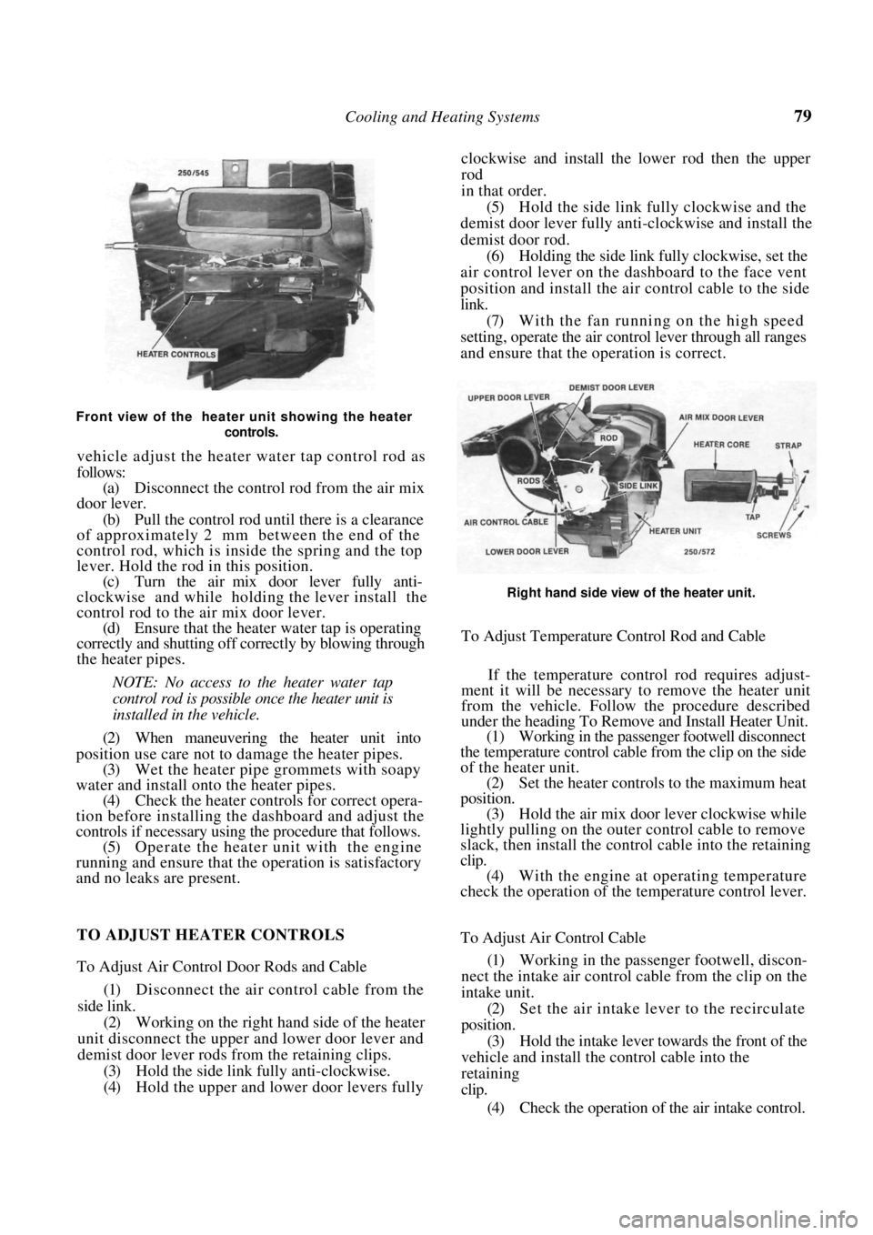
Front view of the heater unit showing the heater controls.
vehicle adjust the heater water tap control rod as
follows:
(a) Disconnect the control rod from the air mix
door lever.
(b) Pull the control rod un til there is a clearance
of approximately 2 mm between the end of the
control rod, which is inside the spring and the top
lever. Hold the rod in this position.
(c) Turn the air mix door lever fully anti-
clockwise and while holding the lever install the
control rod to the air mix door lever. (d) Ensure that the heater water tap is operating
correctly and shutting off correctly by blowing through
the heater pipes.
NOTE: No access to the heater water tap
control rod is possible once the heater unit is
installed in the vehicle.
(2) When maneuvering the heater unit into
position use care not to damage the heater pipes. (3) Wet the heater pipe grommets with soapy
water and install onto the heater pipes. (4) Check the heater controls for correct opera-
tion before installing the dashboard and adjust the
controls if necessary using the procedure that follows. (5) Operate the heater unit with the engine
running and ensure that the operation is satisfactory
and no leaks are present. clockwise and install the lower rod then the upper
rod
in that order.
(5)
Hold the side link fully clockwise and the
demist door lever fully anti-clockwise and install the
demist door rod. (6) Holding the side link fully clockwise, set the
air control lever on the dashboard to the face vent
position and install the air control cable to the side
link. (7) With the fan running on the high speed
setting, operate the air cont rol lever through all ranges
and ensure that the operation is correct.
Right hand side view of the heater unit.
To Adjust Temperature Control Rod and Cable
If the temperature control rod requires adjust-
ment it will be necessary to remove the heater unit
from the vehicle. Follow the procedure described
under the heading To Remove and Install Heater Unit.
(1) Working in the passenger footwell disconnect
the temperature control cable from the clip on the side
of the heater unit. (2) Set the heater controls to the maximum heat
position. (3) Hold the air mix door lever clockwise while
lightly pulling on the outer control cable to remove
slack, then install the control cable into the retaining
clip.
(4) With the engine at operating temperature
check the operation of the temperature control lever.
TO ADJUST HEATER CONTROLS
To Adjust Air Control Door Rods and Cable
(1) Disconnect the air control cable from the
side link. (2) Working on the right hand side of the heater
unit disconnect the upper and lower door lever and
demist door lever rods from the retaining clips.
(3) Hold the side link fully anti-clockwise.
(4) Hold the upper and lower door levers fully To Adjust Air Control Cable
(1)
Working in the passeng er footwell, discon-
nect the intake air control cable from the clip on the
intake unit. (2) Set the air intake lever to the recirculate
position. (3) Hold the intake lever to wards the front of the
vehicle and install the control cable into the
retaining
clip.
(4) Check the operation of the air intake control.
Page 82 of 238

82
FUEL AND ENGINE MANAGEMENT
CAUTION: To prevent severe electrical shock, extreme care must be taken when
working on or near the electronic ignition system as dangerous high tension voltages
are produced in both the primary and secondary circuits. See the text fo\
r
precautionary notes.
SPECIFICATIONS
FUEL INJECTION
Type:
1.6 liter engine .................................. Single point
1.8 liter engine................................... Multi point
FUEL PUMP
Type ................................................................ Electric
Pressure at idle:
1.6 liter engine ..................................... 62-90 kPa
1.8 liter engine ................................ 190-230 kPa
FUEL FILTER
Type ................................................ Inline, disposable
AIR FILTER
Type ................................... Disposable paper element
DISTRIBUTOR
Make ........................................................ Delco Remy
Advance contro l .......................................... Electronic
Rotation of rotor .................................. Anti-clockwise
Firing order....................................................1 -3-4-2
ADJUSTMENTS
Base idle speed ..................................... 550-650 rpm
Ignition timing.......................................... 10° BTDC
TORQUE WRENCH SETTINGS
Throttle body nuts.......................................... 10 Nm
*Throttle body bolts ........................................ 12 Nm
*Fuel hose fittings............................................ 35 Nm
Fuel rail bolts ....................................................8 Nm
Fuel tank drain plug ........................................ 24 Nm
Coolant temperature sensor ............................ 12 Nm
Oxygen sensor .................................................. 40 Nm
MAT sensor..................................................... 14 Nm
*1.6 liter engine
l . 8 liter engine
1. FUEL AND ENGINE MANAGEMENT
TROUBLE SHOOTING
NOTE: The following Trouble Shooting pro-
cedures are basic checks only. If these pro-
cedures fail to locate the fault, refer to the
System Diagnosis and Adjustments heading
for more thorough testing.
Prior to performing any of the following
operations, refer to the Service Precautions
and Procedures heading.
ENGINE WILL NOT START OR HARD TO
START
(1) Water in the fuel: Dr ain the fuel from the
system and renew the fuel filter.
(2) Fault in the power supply: Check the battery,
fusible links and fuses. Check for clean, secure con-
nections, particularly the earth connections. Check the
EG1 and fuel pump relays.
NOTE: If the fuel pump relay fails, power
will be supplied to the fuel pump via the oil
pressure switch. When starting the engine,
Check that the MAP sensor hose is not blocked or split
and ensure that all electrical connections are clean and
secure.