display NISSAN QASHQAI 2010 Owners Manual
[x] Cancel search | Manufacturer: NISSAN, Model Year: 2010, Model line: QASHQAI, Model: NISSAN QASHQAI 2010Pages: 297, PDF Size: 4.09 MB
Page 192 of 297
Downloaded from www.Manualslib.com manuals search engine The cruise control system allows driving at constant
speeds without keeping your foot on the accelerator
pedal.
WARNING
The cruise control system ONLY maintains a
constant vehicle speed, it does not replace
the driver.
Always observe the posted speed limits and
do not set the speed above them.
Do not use the cruise control system when
driving under the following conditions. Doing
so could cause a loss of vehicle control and
result in an accident.
– When it is not possible to keep the vehicleat a constant speed
– When driving in heavy traffic
– When driving in traffic that varies speed
– When driving in windy areas
– When driving on winding or hilly roads
– When driving on slippery (rain, snow, ice, etc.) roads
CAUTION
On manual transmission models, do not shift into
N (Neutral) without depressing the clutch pedal
when the cruise control is set. Should this occur,
depress the clutch pedal and turn the cruise con-
trol main switch off immediately. Failure to do so
may cause engine damage. When the cruise control system is on the speed lim-
iter cannot be operated.
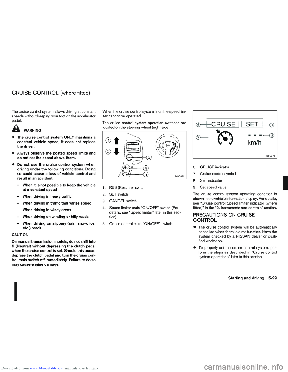
The cruise control system operation switches are
located on the steering wheel (right side).
1.
RES (Resume) switch
2. SET switch
3. CANCEL switch
4. Speed limiter main “ON/OFF” switch (For
details, see “Speed limiter” later in this sec-
tion)
5. Cruise control main “ON/OFF” switch 6.
CRUISE indicator
7. Cruise control symbol
8. SET indicator
9. Set speed value
The cruise control system operating condition is
shown in the vehicle information display. For details,
see “Cruise control/Speed limiter indicator (where
fitted)” in the “2. Instruments and controls” section.
PRECAUTIONS ON CRUISE
CONTROL
The cruise control system will be automatically
cancelled when there is a malfunction. Have the
system checked by a NISSAN dealer or quali-
fied workshop.
To properly set the cruise control system, per-
form the steps as described in “Cruise control
system operations” later in this section.
NSD373
NSD375
CRUISE CONTROL (where fitted)
Starting and driving5-29
Page 193 of 297
Downloaded from www.Manualslib.com manuals search engine CRUISE CONTROL SYSTEM
OPERATIONS
The cruise control system can be set at the follow-
ing speeds:
Engine typeMinimum
speedMaximum speed
1.6 petrol
HR16DE 45 km/h
(30 MPH)MT: 170 km/h (100 MPH)
CVT: 155 km/h (95 MPH)
2.0 petrol
MR20DE MT: 185 km/h (110 MPH)
CVT: 175 km/h (105 MPH)
1.5 diesel
K9K 30 km/h
(20 MPH)
166 km/h (70 MPH)
2.0 diesel
M9R 30 km/h
(18 MPH)
170 km/h (106 MPH)
1.6 diesel
R9M 40 km/h
(25 MPH)
190 km/h (119 MPH)
Turning the cruise control system on
The cruise control system can be switched on after
engine start or when driving.
Push the cruise control main switch
j5 . The
CRUISE indicator and the cruise control symbolj7
will illuminate in the combination meter display.
Setting a cruising speed
1. Accelerate to the desired cruising speed.
2. Push the SET switch
j2 downwards and release
it.
3. The SET indicator
j8 and the set speed valuej9 will be displayed in the combination meter
display. 4. Take your foot off the accelerator pedal.
The vehicle will maintain the set speed.
If the vehicle speed is less than the minimum set
speed (see table), it will not be possible to set
the cruise control system.
Changing a cruising speed
Use any one of the following methods to change the
cruising speed.
Slow the vehicle as normal using the footbrake
pedal, the SET indicatorj8 in the combination
meter will be turned off.
When the vehicle reaches the desired cruising
speed, push and release the SET switch
j2
downwards.
The new set speed value
j9 and SET indicatorj8 will be displayed in the combination meter.
Press the accelerator pedal.
When the vehicle reaches the desired cruising
speed, push and release the SET switch
j2
downwards.
The new set speed value
j9 and SET indicatorj8 will be displayed in the combination meter.
Push and release the RES (resume)j1 switch
upwards or the SET switchj2 downwards to
increase or decrease the set speed in steps of:
1km/hor1MPHforpetrol models or R9M die-
sel models
2km/hor2–3MPHK9K diesel models 2km/hor1MPHforM9R diesel models
Push and hold the RES (resume)j1 switch up-
wards or the SET switchj2 downwards. The
vehicle speed will increase or decrease to the
new set speed.
The new set speed value
j9 will be displayed in the
combination meter.
Passing another vehicle
Depress the accelerator pedal to accelerate. After
releasing the accelerator pedal, the vehicle will re-
turn to the previously set speed.
The set speed value
j9 will flash until the vehicle
returns to the previously set speed.
Cancelling the cruise control system
To cancel a set speed limit, push the CANCEL
switchj3 . The SET indicatorj8 in the combination
meter will be turned off.
The set speed value
j9 will remain displayed, as
this speed is now stored in the cruise control sys-
tem memory.
The cruise control system will also be cancelled
automatically by any of the following:
Pressing the footbrake pedal.
Pressing the clutch pedal.
Moving the gear lever (MT models) or selector
lever (AT or CVT models) to the N (Neutral) posi-
tion.
5-30Starting and driving
Page 194 of 297
Downloaded from www.Manualslib.com manuals search engine If the vehicle slows down more than approxi-
mately 12 km/h (8 MPH) below the set speed.
Resuming a previous cruising speed
If the cruising speed has been cancelled, the set
speed valuej9 will remain displayed in the combi-
nation meter and the speed will be stored in the
cruise control system memory. This cruising speed
can be reactivated by pressing the RES (Resume)
switch
j1 upwards.
If the vehicle speed is less than the minimum set
speed (see table), it will not be possible to re-
sume to the cruising speed.
Turn the cruise control system off
The cruise control system will be turned off when
one of the following operations is performed:
Push the cruise control main “ON/OFF” switchj5 . The cruise control symbolj7 , the CRUISE
indicatorj6 , the SET indicatorj8 , and the set
speed valuej9 will turn off in the combination
meter display
Push the speed limiter main “ON/OFF” switchj5 . The cruise control system information in the
combination meter will be replaced with the
speed limiter information. For details see “Speed
limiter” later in this section.
When the vehicle is stopped and the ignition is
turned to the off position.
Turning off the cruise control system will erase
the cruise control system memory. The speed limiter allows you to set the desired ve-
hicle speed limit. While the speed limiter is acti-
vated, you can perform normal braking and accel-
eration, but the vehicle will not exceed the set speed.
When the vehicle reaches the set speed limit or if
the set speed limit is lower than the actual vehicle
speed, the accelerator pedal will not work until the
vehicle speed drops below the set speed limit.
WARNING
The speed limiter will not automatically brake
the vehicle to the set speed limit.
Always observe posted speed limits. Do not
set the speed above them.
Always confirm the setting status of the speed
limiter in the combination meter display.
When the speed limiter is set, avoid hard ac-
celeration to reach the set limit to ensure that
the system can limit the speed of the vehicle
correctly.
When additional floor mats are used, be sure
that they are correctly secured and that they
cannot interfere with the accelerator pedal.
Mats not adapted to the vehicle may prevent
proper operation of the speed limiter.
When the speed limiter is on the cruise control sys-
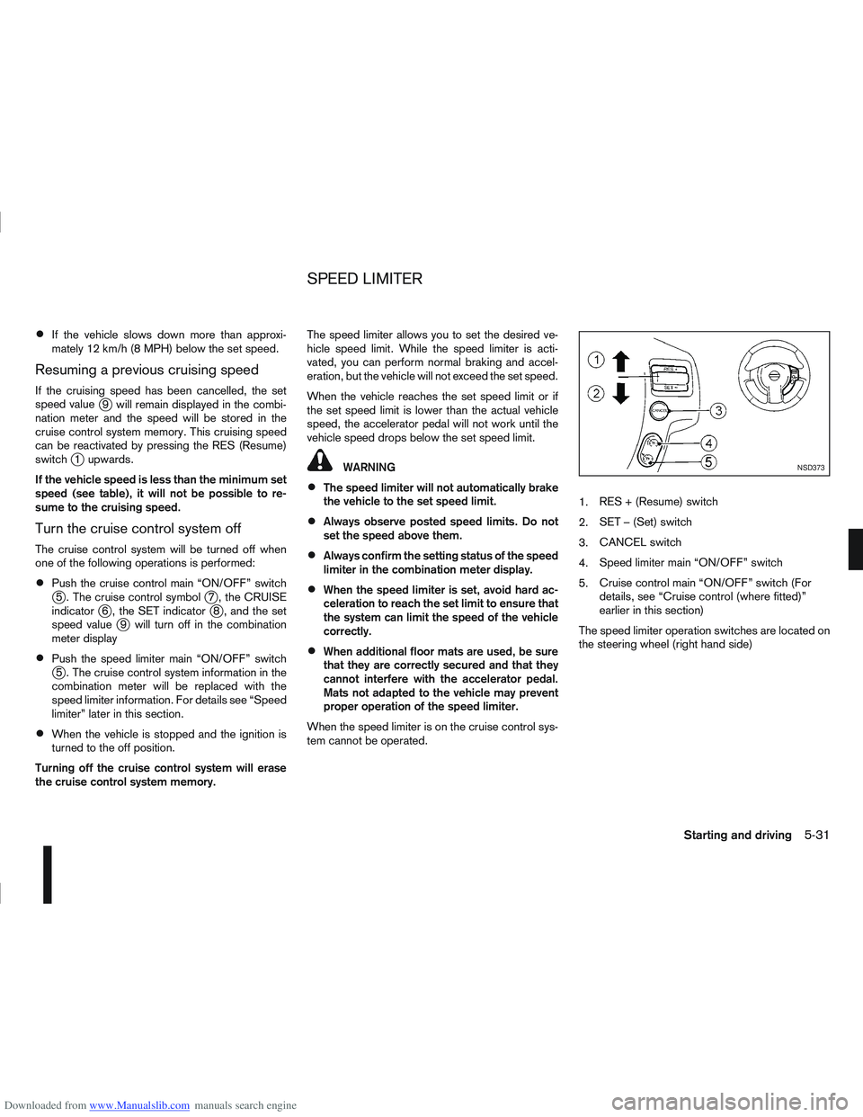
tem cannot be operated. 1.
RES + (Resume) switch
2. SET – (Set) switch
3. CANCEL switch
4. Speed limiter main “ON/OFF” switch
5. Cruise control main “ON/OFF” switch (For
details, see “Cruise control (where fitted)”
earlier in this section)
The speed limiter operation switches are located on
the steering wheel (right hand side)
NSD373
SPEED LIMITER
Starting and driving5-31
Page 195 of 297
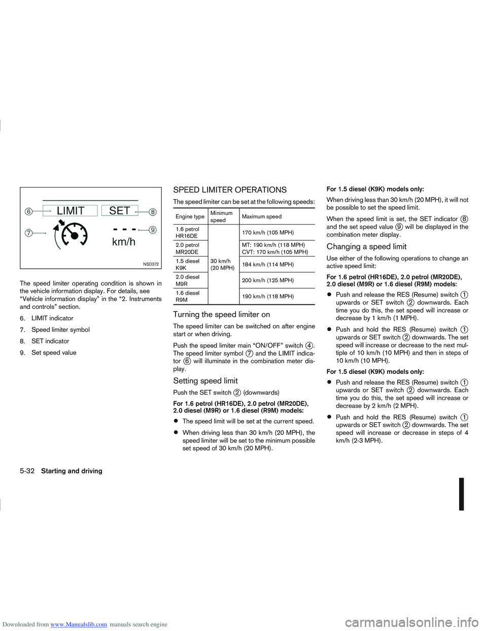
Downloaded from www.Manualslib.com manuals search engine The speed limiter operating condition is shown in
the vehicle information display. For details, see
“Vehicle information display” in the “2. Instruments
and controls” section.
6.LIMIT indicator
7. Speed limiter symbol
8. SET indicator
9. Set speed value
SPEED LIMITER OPERATIONS
The speed limiter can be set at the following speeds:
Engine type Minimum
speedMaximum speed
1.6 petrol
HR16DE
30 km/h
(20 MPH)170 km/h (105 MPH)
2.0 petrol
MR20DE MT: 190 km/h (118 MPH)
CVT: 170 km/h (105 MPH)
1.5 diesel
K9K 184 km/h (114 MPH)
2.0 diesel
M9R 200 km/h (125 MPH)
1.6 diesel
R9M 190 km/h (118 MPH)
Turning the speed limiter on
The speed limiter can be switched on after engine
start or when driving.
Push the speed limiter main “ON/OFF” switch
j4.
The speed limiter symbolj7 and the LIMIT indica-
torj6 will illuminate in the combination meter dis-
play.
Setting speed limit
Push the SET switchj2 (downwards)
For 1.6 petrol (HR16DE), 2.0 petrol (MR20DE),
2.0 diesel (M9R) or 1.6 diesel (R9M) models:
The speed limit will be set at the current speed.
When driving less than 30 km/h (20 MPH), the
speed limiter will be set to the minimum possible
set speed of 30 km/h (20 MPH). For 1.5 diesel (K9K) models only:
When driving less than 30 km/h (20 MPH), it will not
be possible to set the speed limit.
When the speed limit is set, the SET indicator
j8
and the set speed valuej9 will be displayed in the
combination meter display.
Changing a speed limit
Use either of the following operations to change an
active speed limit:
For 1.6 petrol (HR16DE), 2.0 petrol (MR20DE),
2.0 diesel (M9R) or 1.6 diesel (R9M) models:
Push and release the RES (Resume) switchj1
upwards or SET switchj2 downwards. Each
time you do this, the set speed will increase or
decrease by 1 km/h (1 MPH).
Push and hold the RES (Resume) switchj1
upwards or SET switchj2 downwards. The set
speed will increase or decrease to the next mul-
tiple of 10 km/h (10 MPH) and then in steps of
10 km/h (10 MPH).
For 1.5 diesel (K9K) models only:
Push and release the RES (Resume) switchj1
upwards or SET switchj2 downwards. Each
time you do this, the set speed will increase or
decrease by 2 km/h (2 MPH).
Push and hold the RES (Resume) switchj1
upwards or SET switchj2 downwards. The set
speed will increase or decrease in steps of 4
km/h (2-3 MPH).
NSD372
5-32Starting and driving
Page 196 of 297
Downloaded from www.Manualslib.com manuals search engine The new set speed limit valuej9 will be displayed
in the combination meter display.
Cancelling a speed limit
To cancel a set speed limit, push the CANCEL
switchj3 . The SET indicatorj8 in the combination
meter will be turned off. The set speed valuej9 will
remain displayed.
It is also possible to override the speed limiter by
fully depressing the accelerator pedal beyond the
resistance point.
WARNING
The vehicle may accelerate when the speed
limiter cancels.
When additional floor mats are used, be sure
that they are correctly secured and that they
cannot interfere with the accelerator pedal.
Mats not adapted to the vehicle may prevent
proper operation of the speed limiter.
Fully depress the accelerator pedal beyond the re-
sistance point. The speed limiter will be suspended
to allow driving above the set speed. The set speed
value
j9 will flash. The speed limiter will automati-
cally resume when the vehicle speed drops below
the set speed limit.
Resuming a previous set speed
If a set speed limit has been cancelled, the set speed
valuej9 will remain displayed in the combination
meter and the speed will be stored in the speed lim-
iter memory. This speed limit can be reactivated by pressing the
RES (Resume) switch
j1 upwards.
If the current vehicle speed is higher than the previ-
ous set speed, the accelerator pedal will not work
and the set speed value
j9 will flash until the vehicle
speed drops below the set speed limit.
Turning the speed limiter off
The speed limiter system will be turned off when
one of the following operations is performed:
Push the speed limiter main “ON/OFF” switchj4 . The speed limiter symbolj7 , the LIMIT indi-
catorj6 , the SET indicatorj8 , and the set
speed valuej9 will turn off in the combination
meter display.
Push the cruise control main “ON/OFF” switchj5 . The speed limiter information in the combi-
nation meter will be replaced with the cruise con-
trol information. For details see “Cruise control
(where fitted)” earlier in this section.
When the vehicle is stopped and the ignition is
turned to the off position.
Turning off the speed limiter will erase the set
speed limit memory.
Speed limiter malfunction
If the speed limiter malfunctions, the set indicatorj8 in the combination meter display will flash.
Turn the speed limiter off by pushing the speed lim-
iter main “ON/OFF” switch
j4 and have the system
checked by a NISSAN dealer or qualified workshop.
WARNING
Do not park the vehicle over flammable mate-
rials, such as dry grass, waste paper, or rags.
They may ignite and cause a fire.
Safe parking procedures require that:
– The handbrake is applied.
– The gear lever is placed in an appropriate gear for manual transmission models.
– The selector lever is placed in the P (Park) position for automatic transmission or con-
tinuously variable transmission models.
Failure to follow the above recommenda-
tions could cause the vehicle to move un-
expectedly or roll away and result in an
accident.
Never leave the engine running while the ve-
hicle is unattended.
Do not leave children or adults who would
normally require the support of others alone
in your vehicle. Pets should also not be left
alone either. On hot, sunny days, tempera-
tures in a closed vehicle could quickly be-
come high enough to cause severe or possi-
bly fatal injuries to people or animals.
Manual transmission models:
Depress the clutch pedal and place the gear
lever in the R (Reverse) position. When parking
on an uphill gradient, place the gear lever in the
1st (Low gear) position.
PARKING
Starting and driving5-33
Page 224 of 297
Downloaded from www.Manualslib.com manuals search engine 7Appearance and care
Appearance and care
Cleaning exterior...................................................... 7-2
Washing ............................................................. 7-2
Removing spots .................................................. 7-2
Waxing ............................................................... 7-2
Cleaning glass .................................................... 7-3
Cleaning rear-view camera (where fitted) ............ 7-3
Underbody ......................................................... 7-3
Care of wheels ................................................... 7-3
Cleaning alloy wheels ......................................... 7-3
Chrome parts ..................................................... 7-3
Cleaning interior ...................................................... 7-4 Monitor display’s maintenance (where fitted) ....... 7-4
Floor mats .......................................................... 7-4
Cleaning Glass ................................................... 7-4
Plastic parts........................................................ 7-4
Seat belts ........................................................... 7-4
Corrosion protection ................................................ 7-5 Most common factors contributing to vehicle
corrosion ............................................................ 7-5
Environmental factors influence the rate of
corrosion ............................................................ 7-5
To protect your vehicle from corrosion ................ 7-5
Page 226 of 297
Downloaded from www.Manualslib.com manuals search engine Always follow the manufacturer’s instructions
supplied with the wax.
Do not use a wax containing any abrasives,
cutting compounds or cleaners that may dam-
age the vehicle finish.
If the vehicle surface cannot polish easily, ap-
ply a road tar remover prior to waxing the ve-
hicle.
Machine compounding or aggressive polish-
ing on a base coat/clear coat paint finish may
dull the finish or leave swirl marks.
CLEANING GLASS
Use glass cleaner to remove smoke and dust film
from the glass surfaces. It is normal for glass to
become coated with a film after the vehicle is parked
in the hot sun. Glass cleaner and a soft cloth will
easily remove this film.
CLEANING REAR-VIEW CAMERA
(where fitted)
Clean the transparent camera cover regularly. If dirt,
rain or snow attaches to the cover, the monitor may
not display objects clearly.
CAUTION
Do not use alcohol, benzine or thinner to clean
the transparent camera cover. This will cause
discoloration. To clean the cover, first use a
cloth dampened with diluted mild cleaning
agent and then wipe with a dry cloth.
Do not use body wax on the transparent cam-
era cover.
When washing the vehicle with a high pres-
sure water spray, make sure not to spray it
around the transparent camera cover. Other-
wise, water may enter the camera unit caus-
ing water condensation on the lens and it may
result in a malfunction or an electric shock.
UNDERBODY
In areas where road salt is used in the winter, the
vehicle’s underbody must be cleaned regularly. This
will prevent dirt and salt from building up and caus-
ing underbody and suspension corrosion.
Before the winter period and again in the spring, the
underseal must be checked and, if necessary, re-
treated.
CARE OF WHEELS
Wash the wheels when washing the vehicle to
maintain their appearance.
Clean the inner side of the wheels when the
wheel is changed or the underside of the vehicle
is washed.
Do not use abrasive cleaners when washing the
wheels.
Inspect wheel rims regularly for dents or corro-
sion. This may cause loss of pressure or damage
the tyre bead.
NISSAN recommends that the road wheels be
waxed to protect against road salt in areas where
it is used during winter.
CLEANING ALLOY WHEELS
Wash the wheels regularly with a sponge damp-
ened in a mild soap solution, especially during win-
ter in areas where road salt is used. The salt residue
from road salt could discolour the wheels if it is not
washed off regularly.
CAUTION
Follow the directions as described below in order
to avoid staining or discolouring of the wheels.
Do not use a cleaner that contains strong con-
tents of acid or alkali to clean the wheels.
Do not apply wheel cleaner when the wheels
are hot. The wheel temperature should be the
same as ambient temperature.
Rinse the wheel to completely remove the
cleaner within 15 minutes after the cleaner
has been applied.
CHROME PARTS
Clean all chrome parts regularly with a nonabrasive
chrome polish to maintain the finish.
Appearance and care7-3
Page 227 of 297
Downloaded from www.Manualslib.com manuals search engine Occasionally remove loose dust from the interior
trim, plastic parts and seats using a vacuum cleaner
or soft bristled brush. Wipe the vinyl and leather sur-
faces with a clean, soft cloth dampened in mild soap
solution, then wipe clean with a dry, soft cloth.
Regular care and cleaning is required in order to
maintain the appearance of the leather.
Before using any fabric protector, read the manu-
facturer’s recommendations. Some fabric protec-
tors contain chemicals that may stain or bleach the
seat material.
Use a soft cloth dampened only with water to clean
the meter and gauge lens covers.
CAUTION
Never use benzine, thinner or any similar ma-
terial.
Small dirt particles can be abrasive and dam-
aging to leather surfaces and should be re-
moved promptly. Do not use saddle soap, car
waxes, polishes, oils cleaning fluids, solvents,
detergents or ammonia based cleaners as
they may damage the leather’s natural finish.
Never use fabric protectors unless recom-
mended by the manufacturer.
Do not use glass or plastic cleaner on meter
or gauge lens covers. It may damage the lens
covers.
MONITOR DISPLAY’S MAINTENANCE
(where fitted)
To clean the display screen, first turn the ignition
off and wipe it with a dry soft cloth.
Never use a rough cloth, alcohol, benzine, thin-
ner, any kind of solvent, or paper tissues with
chemical cleaning agent. They would scratch or
deteriorate the panel.
Do not splash any liquid such as water or car fra-
grance on the display. Contact with liquid will
cause the system to malfunction and damage
the hardware.
In case of extreme stain, use a small amount of
neutral detergent with a soft cloth. Never soak
the screen display with water detergent.
FLOOR MATS
The use of NISSAN floor mats can extend the life of
your vehicle carpet and make it easier to clean the
interior. Regardless of what mats are used, be sure
they are fitted for your vehicle and are properly posi-
tioned in the foot well to prevent interference with
pedal operation. Mats should be maintained with
regular cleaning and replaced if they become exces-
sively worn.
CLEANING GLASS
Use glass cleaner to remove smoke and dust film
from the glass surfaces. It is normal for glass to
become coated with a film after the vehicle is parked
in the hot sun. Glass cleaner and a soft cloth will
easily remove this film.CAUTION
When cleaning the inside of the windows, do not
use sharp-edged tools, abrasive cleaners or chlo-
rine-based disinfectant cleaners. They could
damage elements in the rear windows (such as
the window defogger).
Inside rear-view mirror (Automatic
anti-dazzling, where fitted)
Use a soft cloth dampened only with water to clean
the automatic anti-dazzling inside rear view mirror
(where fitted).
CAUTION
Do not use glass cleaner. Doing so will reduce
the sensitivity of the sensor, resulting in improper
operation.
PLASTIC PARTS
Plastic parts can be cleaned with a mild soap solu-
tion. If the dirt cannot be easily removed, use a plas-
tic cleaner. Do not use any solvents.
SEAT BELTS
WARNING
Do not allow wet seat belts to roll up in the
retractor.
Never use bleach, dye or chemical solvents to
clean the seat belts, since these materials
may severely weaken the seat belt webbing.
CLEANING INTERIOR
7-4Appearance and care
Page 249 of 297
Downloaded from www.Manualslib.com manuals search engine Battery (Type A)
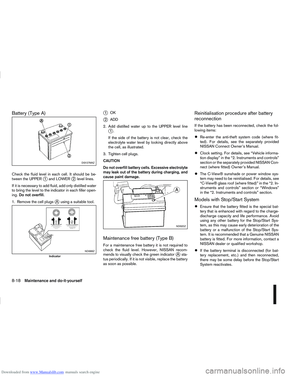
Check the fluid level in each cell. It should be be-
tween the UPPERj1 and LOWERj2 level lines.
If it is necessary to add fluid, add only distilled water
to bring the level to the indicator in each filler open-
ing. Do not overfill.
1. Remove the cell plugs
jA using a suitable tool.
j1 OK
j2ADD
2. Add distilled water up to the UPPER level line
j1.
If the side of the battery is not clear, check the
electrolyte water level by looking directly above
the cell, as illustrated.
3. Tighten cell plugs.
CAUTION
Do not overfill battery cells. Excessive electrolyte
may leak out of the battery during charging, and
cause paint damage.
Maintenance free battery (Type B)
For a maintenance free battery it is not required to
check the fluid level. However, NISSAN recom-
mends to visually check the green indicator
jA sta-
tus periodically. If it is not visible, replace the battery
as soon as possible.
Reinitialisation procedure after battery
reconnection
If the battery has been reconnected, check the fol-
lowing items:
Re-enter the anti-theft system code (where fit-
ted). For details, see the separately provided
NISSAN Connect Owner’s Manual.
Clock setting. For details, see “Vehicle informa-
tion display” in the “2. Instruments and controls”
section or the separately provided NISSAN Con-
nect (where fitted) Owner’s Manual.
The C-View® sunshade or power window sys-
tem may need to be reinitialised. For details, see
“C-View® glass roof (where fitted)” in the “2. In-
struments and controls” section or “Windows”
in the “2. Instruments and controls” section.
Models with Stop/Start System
Ensure that the battery fitted is the special bat-
tery that is enhanced with regard to the charge-
discharge capacity and life performance. Avoid
using any other battery for the Stop/Start Sys-
tem, as this may cause early deterioration of the
battery or a malfunction of the Stop/Start Sys-
tem. It is recommended that a Genuine NISSAN
battery is fitted. For more information, contact a
NISSAN dealer or qualified workshop.
If the battery terminal is disconnected (for bat-
tery replacement, etc.) and then reconnected,
there may be some delay before the Stop/Start
System reactivates.
DI0137MAZ
NDI688Z
Indicator
NDI920Z
8-18Maintenance and do-it-yourself
Page 284 of 297
Downloaded from www.Manualslib.com manuals search engine Display
– Vehicle information display ............................................. 2-11
Door locks ........................................................................\
.... 3-9
– Back door ..................................................................... 3-12
– Child safety rear door locks ........................................... 3-11
– Drive away door locking ................................................. 3-11
– Locking/unlocking with the key — vehicle dead battery .... 3-9
– Power door lock switch ................................................. 3-10
– Remote keyless entry system ........................................... 3-3
– Super Lock system .......................................................... 3-9
– When leaving the vehicle ............................................... 3-10
Drive belts ........................................................................\
... 8-21
Driving
– Care when driving ........................................................... 5-6
– Cold weather driving ..................................................... 5-42
– Driving four-wheel drive (4WD) safely ............................ 5-27
– Driving on wet road ......................................................... 5-6
– Driving the vehicle ......................................................... 5-12
– Driving under winter conditions ........................................ 5-6
– Driving with automatic transmission ...................... 5-14, 5-17
– Driving with continuously variable transmission (Models withmanual shift) .................................................................. 5-14
– Driving with continuously variable transmission (Models without manual shift) .................................................................. 5-17
– Driving with manual transmission ................................... 5-12
– On-pavement and off-road driving precautions ................. 5-4
– Precautions when starting and driving .............................. 5-3
– Stop/Start System ......................................................... 5-21
E
Electronic Stability Programme (ESP) system ...................... 5-40
– ESP OFF switch ........................................................... 5-42
Emergency tyre puncture repair kit ............................... 6-7, 8-34
Emergency/mechanical key ................................................... 3-3 Engine
– Before starting the engine ................................................ 5-2
– Changing engine coolant ................................................. 8-6
– Changing engine oil ......................................................... 8-9
– Changing engine oil filter ............................................... 8-11
– Checking engine coolant level ......................................... 8-6
– Checking engine oil level ................................................. 8-8
– Data ........................................................................\
........ 9-7
– Engine cold start period ................................................... 5-6
– Engine compartment ................................................ 0-7, 8-5
– Engine coolant ............................................................... 5-43
– Engine coolant temperature gauge ................................... 2-2
– Engine cooling system ..................................................... 8-6
– Engine oil ........................................................................\
8-8
– Engine overheat ............................................................. 6-12
– Engine serial number ....................................................... 9-9
– Fuel filter (Diesel engine models) ................................... 8-13
– Starting the engine ........................................................ 5-11
Exhaust gas (Carbon Monoxide) ............................................ 5-3
Exterior lights ...................................................................... 8-27
F
Filter
– Air cleaner filter ............................................................. 8-21
– Air conditioner filter .............................................. 4-17, 4-21
– Fuel filter (Diesel engine models) ................................... 8-13
Floor mats ........................................................................\
..... 7-4
Fluid
– Automatic transmission fluid (ATF) ................................. 8-14
– Brake and clutch fluid .................................................... 8-15
– Continuously variable transmission fluid ......................... 8-14
– Window washer/headlight cleaner fluid .......................... 8-16
Fog light
– Front fog light ................................................................ 2-26
– Rear fog light ................................................................. 2-27
Index10-3