change wheel NISSAN QASHQAI 2012 Owners Manual
[x] Cancel search | Manufacturer: NISSAN, Model Year: 2012, Model line: QASHQAI, Model: NISSAN QASHQAI 2012Pages: 297, PDF Size: 4.09 MB
Page 26 of 297
Downloaded from www.Manualslib.com manuals search engine tened. The seat belt warning shows a filled circle
when the ignition switch is turned to the ON position
and an empty circle when the related seat belt has
been securely fastened, or after approximately 35
seconds after engine start, or when acknowledged
by the driver pushing the steering wheel switch
ji
(where fitted).
NOTE
If there is a change in (2nd row) rear seat belt
status during a journey then the applicable
symbol for any unbuckled seat will show again
for a further 35 seconds.
The front passenger seat belt warning light
will not illuminate if the seat is unoccupied.
Seat belts for 3rd row seats (where fitted) are
not part of the seat belt warning monitoring
system.
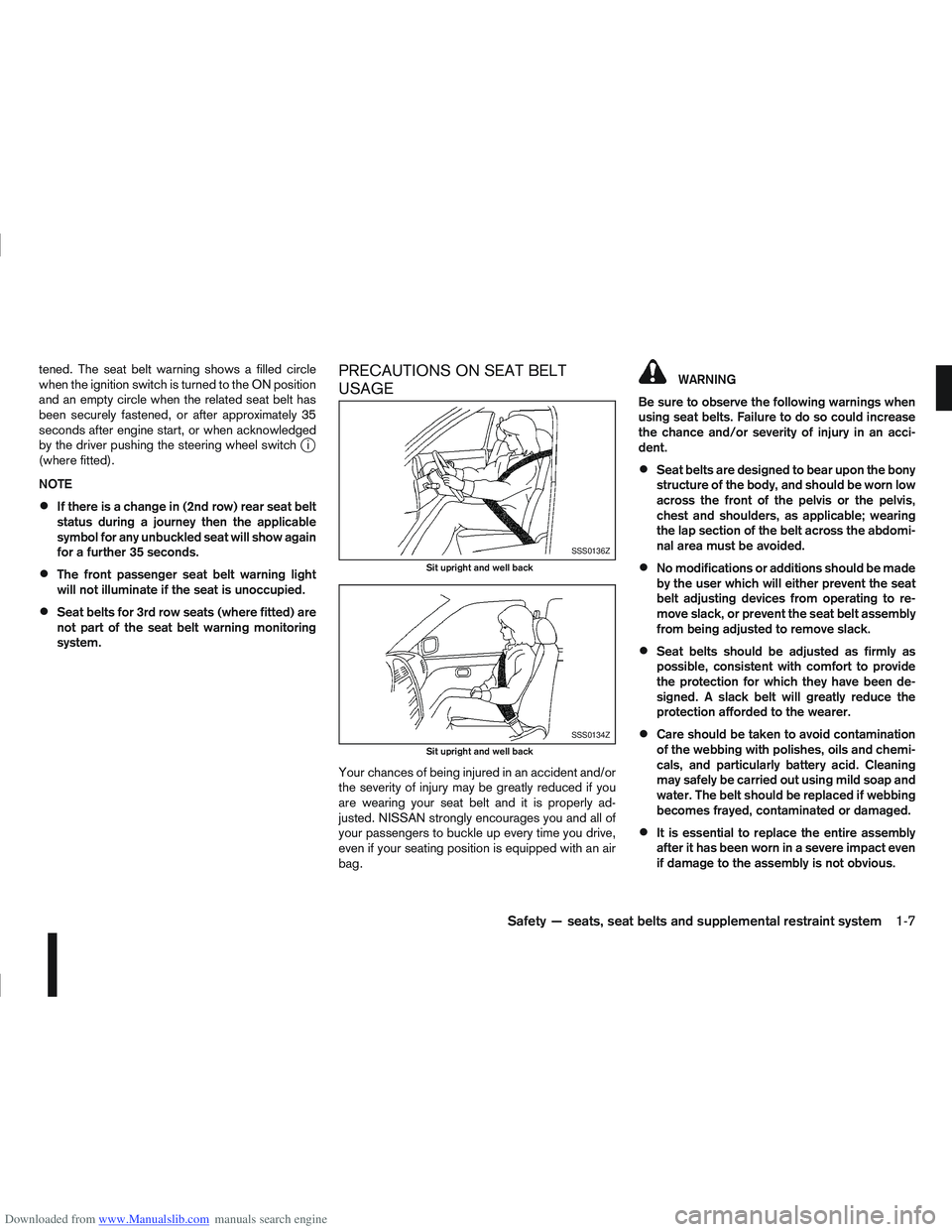
PRECAUTIONS ON SEAT BELT
USAGE
Your chances of being injured in an accident and/or
the severity of injury may be greatly reduced if you
are wearing your seat belt and it is properly ad-
justed. NISSAN strongly encourages you and all of
your passengers to buckle up every time you drive,
even if your seating position is equipped with an air
bag.
WARNING
Be sure to observe the following warnings when
using seat belts. Failure to do so could increase
the chance and/or severity of injury in an acci-
dent.
Seat belts are designed to bear upon the bony
structure of the body, and should be worn low
across the front of the pelvis or the pelvis,
chest and shoulders, as applicable; wearing
the lap section of the belt across the abdomi-
nal area must be avoided.
No modifications or additions should be made
by the user which will either prevent the seat
belt adjusting devices from operating to re-
move slack, or prevent the seat belt assembly
from being adjusted to remove slack.
Seat belts should be adjusted as firmly as
possible, consistent with comfort to provide
the protection for which they have been de-
signed. A slack belt will greatly reduce the
protection afforded to the wearer.
Care should be taken to avoid contamination
of the webbing with polishes, oils and chemi-
cals, and particularly battery acid. Cleaning
may safely be carried out using mild soap and
water. The belt should be replaced if webbing
becomes frayed, contaminated or damaged.
It is essential to replace the entire assembly
after it has been worn in a severe impact even
if damage to the assembly is not obvious.
SSS0136Z
Sit upright and well back
SSS0134Z
Sit upright and well back
Safety — seats, seat belts and supplemental restraint system1-7
Page 34 of 297
Downloaded from www.Manualslib.com manuals search engine forces in another type of collision are similar to those
of a higher severity side impact. They are designed
to inflate on the side where the vehicle is impacted.
They may not inflate in certain side collisions. Ve-
hicle damage (or lack of it) is not always an indica-
tion of proper supplemental side air bag operation.
When the supplemental side air bag and curtain air
bag inflate, a fairly loud noise may be heard, fol-
lowed by a release of smoke. This smoke is not
harmful and does not indicate a fire. However, care
should be taken not to inhale it, as it may cause irri-
tation and choking. Occupants with a history of
breathing difficulties, such as asthma, should get
fresh air promptly.
Supplemental side air bags, along with the use of
seat belts, help to cushion the impact force on the
chest of the front occupants. Curtain air bags help
to cushion the impact force to the head of occu-
pants in the front and rear outer seating positions.
They can help save lives and reduce serious inju-
ries. However, an inflating side air bag and curtain
air bag may cause abrasions or other injuries.
Supplemental side air bags and curtain air bags do
not provide restraint to the lower body.
The seat belts should be correctly worn and the
driver and passenger seated upright, and as far as
is practical, away from the side air bag. Rear seat
passengers should be seated as far away as practi-
cal from the door finishers and side roof rails. The
side air bags and curtain air bags inflate quickly in
order to help protect the front occupants. Because
of this, the force of the side air bag and curtain air
bag inflating can increase the risk of injury if theoccupant is too close to, or is against, these air bag
modules during inflation. The side air bag and cur-
tain air bag will deflate quickly after the collision is
over.
WARNING
Directly after inflation, several air bag system
components will be hot. Do not touch them;
you may severely burn yourself.
No unauthorised changes should be made to
any components or wiring of the air bag sys-
tem. This is to prevent accidental inflation of
the air bag or damage to the air bag system.
Tampering with the air bag system may result
in serious personal injury. Tampering includes
making changes to the steering wheel and
the instrument panel assembly by placing ma-
terial over the steering pad and above the
dashboard, or by installing additional trim ma-
terial around the air bag system.
Do not attach any objects to the steering
wheel pad or to the instrument panel. Objects
attached to the steering wheel pad and in-
strument panel may become dangerous pro-
jectiles and cause injury if the air bag inflates.
Work on and around the air bag system should
be done by a NISSAN dealer or qualified work-
shop. Installation of electrical equipment
should be done by a NISSAN dealer or quali-
fied workshop. The yellow SRS wiring har-
nesses* should not be modified or discon-
nected. Unauthorised electrical test equip-
ment and probing devices should not be used
on the air bag system.
* SRS wiring harnesses are covered with yellow insulation either just before the harness con-
nectors or on the complete harness, for easy
identification.
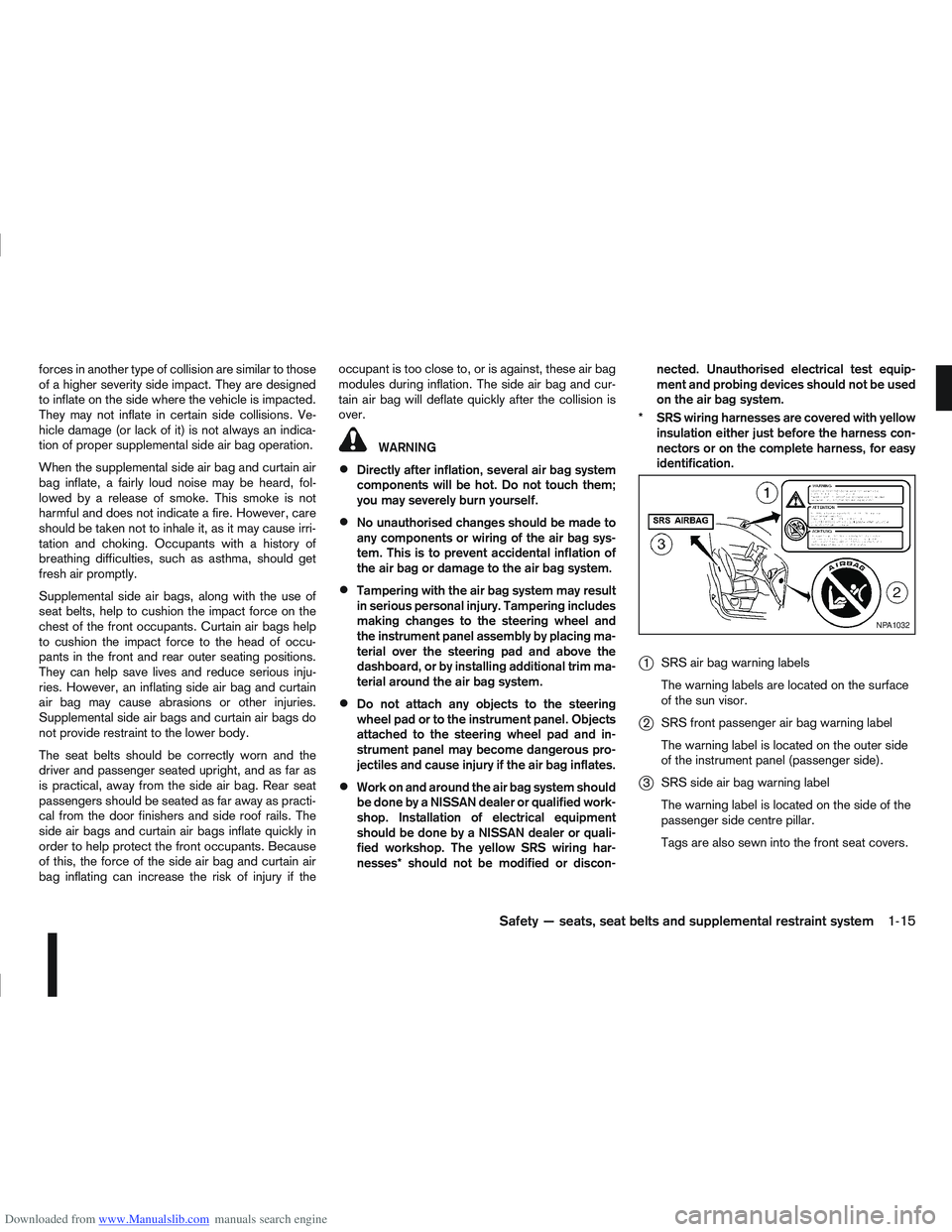
j1 SRS air bag warning labels
The warning labels are located on the surface
of the sun visor.
j2SRS front passenger air bag warning label
The warning label is located on the outer side
of the instrument panel (passenger side).
j3SRS side air bag warning label
The warning label is located on the side of the
passenger side centre pillar.
Tags are also sewn into the front seat covers.
NPA1032
Safety — seats, seat belts and supplemental restraint system1-15
Page 55 of 297
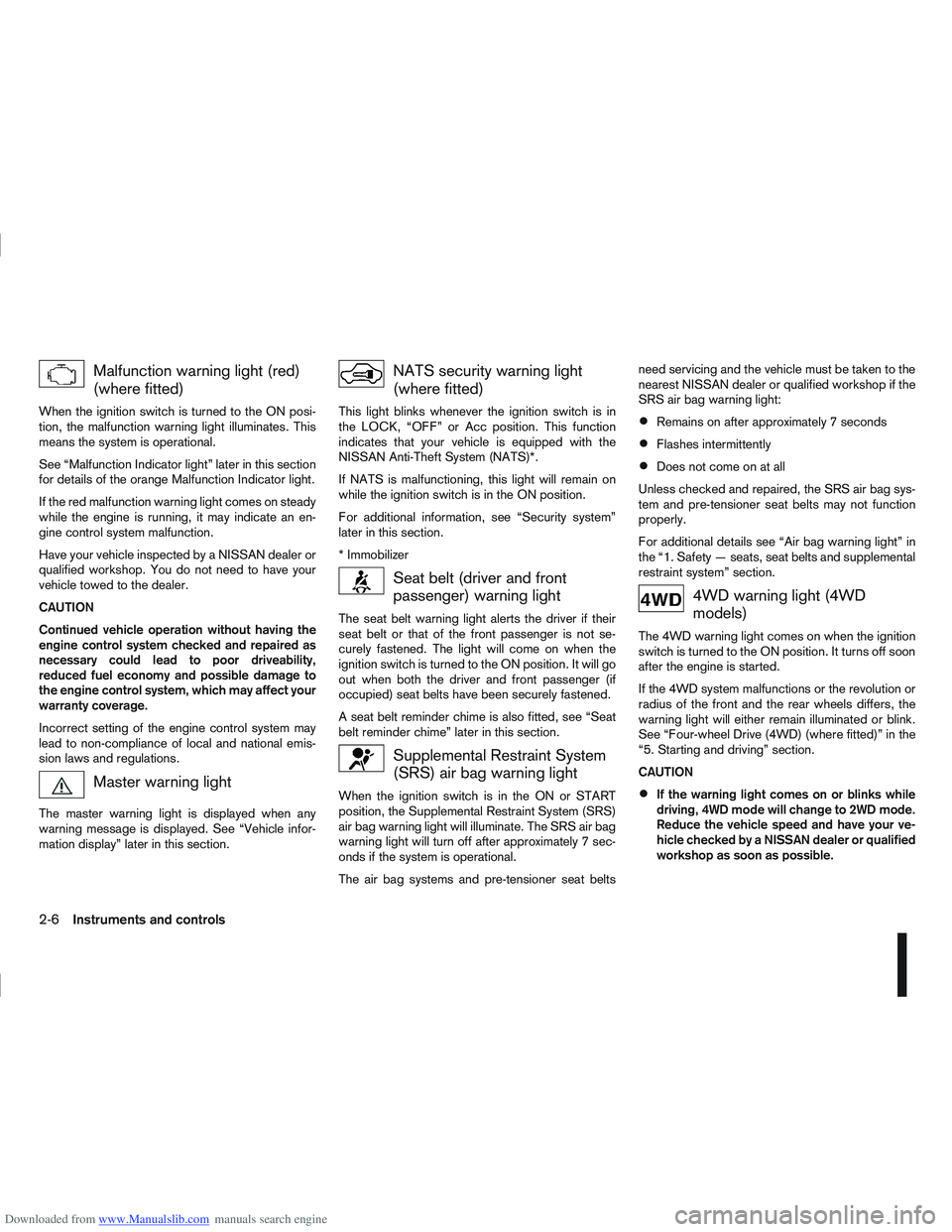
Downloaded from www.Manualslib.com manuals search engine Malfunction warning light (red)
(where fitted)
When the ignition switch is turned to the ON posi-
tion, the malfunction warning light illuminates. This
means the system is operational.
See “Malfunction Indicator light” later in this section
for details of the orange Malfunction Indicator light.
If the red malfunction warning light comes on steady
while the engine is running, it may indicate an en-
gine control system malfunction.
Have your vehicle inspected by a NISSAN dealer or
qualified workshop. You do not need to have your
vehicle towed to the dealer.
CAUTION
Continued vehicle operation without having the
engine control system checked and repaired as
necessary could lead to poor driveability,
reduced fuel economy and possible damage to
the engine control system, which may affect your
warranty coverage.
Incorrect setting of the engine control system may
lead to non-compliance of local and national emis-
sion laws and regulations.
Master warning light
The master warning light is displayed when any
warning message is displayed. See “Vehicle infor-
mation display” later in this section.
NATS security warning light
(where fitted)
This light blinks whenever the ignition switch is in
the LOCK, “OFF” or Acc position. This function
indicates that your vehicle is equipped with the
NISSAN Anti-Theft System (NATS)*.
If NATS is malfunctioning, this light will remain on
while the ignition switch is in the ON position.
For additional information, see “Security system”
later in this section.
* Immobilizer
Seat belt (driver and front
passenger) warning light
The seat belt warning light alerts the driver if their
seat belt or that of the front passenger is not se-
curely fastened. The light will come on when the
ignition switch is turned to the ON position. It will go
out when both the driver and front passenger (if
occupied) seat belts have been securely fastened.
A seat belt reminder chime is also fitted, see “Seat
belt reminder chime” later in this section.
Supplemental Restraint System
(SRS) air bag warning light
When the ignition switch is in the ON or START
position, the Supplemental Restraint System (SRS)
air bag warning light will illuminate. The SRS air bag
warning light will turn off after approximately 7 sec-
onds if the system is operational.
The air bag systems and pre-tensioner seat beltsneed servicing and the vehicle must be taken to the
nearest NISSAN dealer or qualified workshop if the
SRS air bag warning light:
Remains on after approximately 7 seconds
Flashes intermittently
Does not come on at all
Unless checked and repaired, the SRS air bag sys-
tem and pre-tensioner seat belts may not function
properly.
For additional details see “Air bag warning light” in
the “1. Safety — seats, seat belts and supplemental
restraint system” section.
4WD warning light (4WD
models)
The 4WD warning light comes on when the ignition
switch is turned to the ON position. It turns off soon
after the engine is started.
If the 4WD system malfunctions or the revolution or
radius of the front and the rear wheels differs, the
warning light will either remain illuminated or blink.
See “Four-wheel Drive (4WD) (where fitted)” in the
“5. Starting and driving” section.
CAUTION
If the warning light comes on or blinks while
driving, 4WD mode will change to 2WD mode.
Reduce the vehicle speed and have your ve-
hicle checked by a NISSAN dealer or qualified
workshop as soon as possible.
2-6Instruments and controls
Page 63 of 297
Downloaded from www.Manualslib.com manuals search engine For more information, see “Integrated keyfob/re-
mote control system” in the “3. Pre-driving checks
and adjustments” section.
j11Intelligent Key convenience mode alert
The Intelligent Key convenience mode alert shows
to confirm that convenience mode has been acti-
vated. See “Switching from Convenience mode to
Anti-hijack mode” in the “3. Pre-driving checks and
adjustments” section.
j12Intelligent Key anti–hijack alert
The Intelligent Key anti–hijack alert shows to con-
firm that anti-hijack mode has been activated. See
“Switching from Convenience mode to Anti-hijack
mode” in the “3. Pre-driving checks and
adjustments” section.
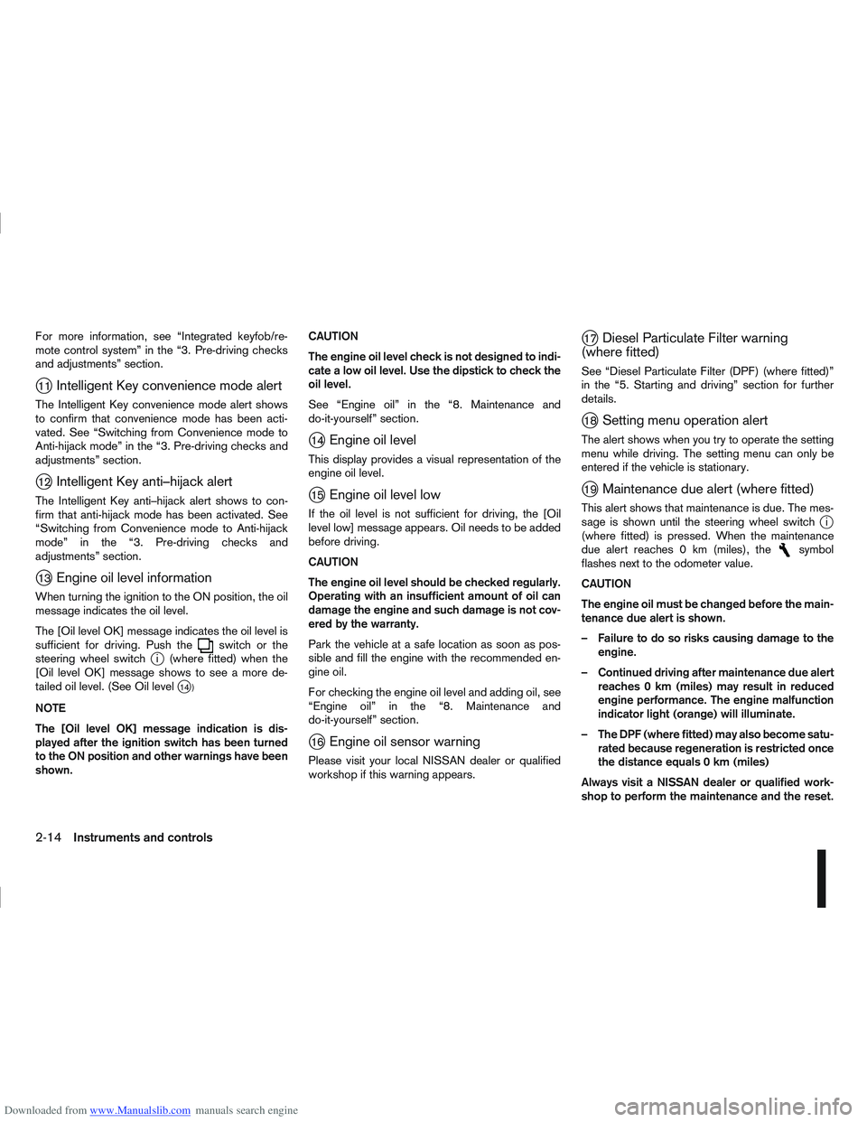
j13Engine oil level information
When turning the ignition to the ON position, the oil
message indicates the oil level.
The [Oil level OK] message indicates the oil level is
sufficient for driving. Push the
switch or the
steering wheel switchji (where fitted) when the
[Oil level OK] message shows to see a more de-
tailed oil level. (See Oil level
j14 )
NOTE
The [Oil level OK] message indication is dis-
played after the ignition switch has been turned
to the ON position and other warnings have been
shown. CAUTION
The engine oil level check is not designed to indi-
cate a low oil level. Use the dipstick to check the
oil level.
See “Engine oil” in the “8. Maintenance and
do-it-yourself” section.
j14Engine oil level
This display provides a visual representation of the
engine oil level.
j15Engine oil level low
If the oil level is not sufficient for driving, the [Oil
level low] message appears. Oil needs to be added
before driving.
CAUTION
The engine oil level should be checked regularly.
Operating with an insufficient amount of oil can
damage the engine and such damage is not cov-
ered by the warranty.
Park the vehicle at a safe location as soon as pos-
sible and fill the engine with the recommended en-
gine oil.
For checking the engine oil level and adding oil, see
“Engine oil” in the “8. Maintenance and
do-it-yourself” section.
j16Engine oil sensor warning
Please visit your local NISSAN dealer or qualified
workshop if this warning appears.
j17Diesel Particulate Filter warning
(where fitted)
See “Diesel Particulate Filter (DPF) (where fitted)”
in the “5. Starting and driving” section for further
details.
j18Setting menu operation alert
The alert shows when you try to operate the setting
menu while driving. The setting menu can only be
entered if the vehicle is stationary.
j19Maintenance due alert (where fitted)
This alert shows that maintenance is due. The mes-
sage is shown until the steering wheel switchji
(where fitted) is pressed. When the maintenance
due alert reaches 0 km (miles), the
symbol
flashes next to the odometer value.
CAUTION
The engine oil must be changed before the main-
tenance due alert is shown.
– Failure to do so risks causing damage to the engine.
– Continued driving after maintenance due alert reaches 0 km (miles) may result in reduced
engine performance. The engine malfunction
indicator light (orange) will illuminate.
– The DPF (where fitted) may also become satu- rated because regeneration is restricted once
the distance equals 0 km (miles)
Always visit a NISSAN dealer or qualified work-
shop to perform the maintenance and the reset.
2-14Instruments and controls
Page 64 of 297
![NISSAN QASHQAI 2012 Owners Manual Downloaded from www.Manualslib.com manuals search engine However reset is possible (only after the oil was
changed) using the [Service] menu item in the
[Settings] menu. See “[Maintenance]” later NISSAN QASHQAI 2012 Owners Manual Downloaded from www.Manualslib.com manuals search engine However reset is possible (only after the oil was
changed) using the [Service] menu item in the
[Settings] menu. See “[Maintenance]” later](/img/5/56764/w960_56764-63.png)
Downloaded from www.Manualslib.com manuals search engine However reset is possible (only after the oil was
changed) using the [Service] menu item in the
[Settings] menu. See “[Maintenance]” later in this
section
Have the vehicle inspected by a NISSAN dealer
or qualified workshop if these conditions occur.
j20Distance to maintenance alert
(where fitted)
This alert reminds when maintenance is due in the
shown distance. The alert is shown for 10 seconds
at ignition ON, when the distance to the next main-
tenance interval is below 5000 km (3100 Miles).
The message is shown until the steering wheel
switch
ji (where fitted) is pressed.
NOTE
Visit a NISSAN dealer or qualified workshop
before the maintenance due alertj19reaches
0 km (miles) to perform maintenance (oil
change).
The maintenance interval will reduce faster
with certain types of driving, especially at low
speeds in urban conditions.
j21Tyre change alert
You can set a distance for changing tyres. See
“[Maintenance]” later in this section
j22Maintenance alert
You can set a distance for a non specific mainte-
nance item. See “[Maintenance]” later in this sec-
tion
j23Low temperature warning
If, during driving, the temperature falls below 4ºC
this alert will appear to indicate low outside air tem-
perature. You can switch the low temperature warn-
ing [On] or [Off]. See “[Units]” later in this section
CAUTION
Even if the alert is not on, there is no guarantee
that the road is free of hazards caused by in-
clement weather.
NOTE
The outside air temperature sensor is located at
the front of the vehicle. At low speeds the sensor
can be affected by engine heat, heat reflected
from the road surface and exhaust from other
vehicles, these influences can cause the display
to be inaccurate. To compensate, the outside air
temperature display is designed to react slowly
to increasing temperatures, but quickly to falling
temperatures.
j24Low fuel warning
This warning appears when the fuel level in the tank
is getting low. Refuel as soon as it is convenient,
preferably before the fuel gauge reaches the empty
position. For more information, see “Fuel gauge”
earlier in this section.
j25Driver alert
This warning appears when the previously set time
for a break is reached. You can set the time for up
to 6 hours in the setting menu. (See “Settings menu”
later in this section.)
Stop/Start System (where fitted)
For more information, see “Stop/Start System
(where fitted)” in the “5. Starting and driving” sec-
tion
j26Engine stop:
If the engine stops when the Stop/Start System is
activated, the message is shown.
j27Auto start deactivation:
If the engine stops when the Stop/Start System is
activated, and will not start automatically, the mes-
sage is shown.
j28System fault:
If the Stop/Start System is activated, but does not
operate correctly, the message is shown. Visit a
NISSAN dealer or qualified workshop.
Activating or deactivating using the Stop/Start
System OFF switch:
Using the Stop/Start System OFF switch activates
or deactivates the Stop/Start System. This is shown
in the vehicle information display:
j29 :The Stop/Start System OFF switch is
pushed to the “ON” position.
j30 :The Stop/Start System OFF switch is pushed to
the “OFF” position.
Instruments and controls2-15
Page 65 of 297
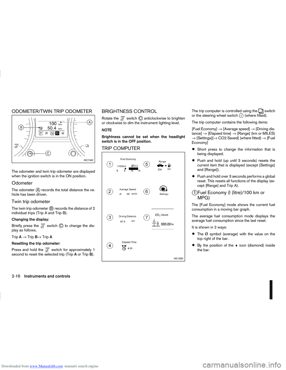
Downloaded from www.Manualslib.com manuals search engine ODOMETER/TWIN TRIP ODOMETER
The odometer and twin trip odometer are displayed
when the ignition switch is in the ON position.
Odometer
The odometerjA records the total distance the ve-
hicle has been driven.
Twin trip odometer
The twin trip odometerjB records the distance of 2
individual trips (Trip A and Trip B).
Changing the display:
Briefly press the
switchjC to change the dis-
play as follows.
Trip A→ Trip B→ TripA
Resetting the trip odometer:
Press and hold the
switch for approximately 1
second to reset the selected trip (Trip Aor Trip B).
BRIGHTNESS CONTROL
Rotate theswitchjC anticlockwise to brighten
or clockwise to dim the instrument lighting level.
NOTE
Brightness cannot be set when the headlight
switch is in the OFF position.
TRIP COMPUTER
The trip computer is controlled using theswitch
or the steering wheel switchji (where fitted).
The trip computer contains the following items:
[Fuel Economy] →[Average speed] →[Driving dis-
tance] →[Elapsed time] →[Range] (km or MILES)
→ [Settings][→ CO2 Saved] (where fitted) →[Fuel
Economy]
Short press to change the information that is
being displayed.
Push and hold (up until 3 seconds) resets the
current item that is displayed (except [Settings]
and [Range]).
Push and hold over 3 seconds performs a global
reset. This resets all functions of the display (ex-
cept [Range] and Trip A).
j1 Fuel Economy (l (litre)/100 km or MPG)
The [Fuel Economy] mode shows the current fuel
consumption in a moving bar graph.
The average fuel consumption mode displays the
average fuel consumption since the last reset.
It is shown in 2 ways:
The Ø symbol (average) with the value on the
top right of the bar.
By the position of the ♦icon (diamond) inside
the bar.
NIC1542
NIC1650
2-16Instruments and controls
Page 108 of 297
Downloaded from www.Manualslib.com manuals search engine 4Display screen, heater and air conditioner,
and audio system
Display screen, heater and air conditioner,
and
audio system
Rear-view monitor (where fitted)............................... 4-2
How to read the displayed lines .......................... 4-2
Rear-view monitor setting.................................... 4-3
Operating tips..................................................... 4-3
Around view monitor (where fitted)........................... 4-4 Operation ........................................................... 4-6
Guide lines ......................................................... 4-7
Difference between predictive and actual
distances ............................................................ 4-9
How to adjust the screen view ............................ 4-11
Operating tips..................................................... 4-11
Vents ....................................................................... 4-12 Side and centre vents ......................................... 4-12
High level vent (where fitted) ............................... 4-12
Heater and air conditioner operation ........................ 4-12 Manual air conditioner......................................... 4-13
Automatic air conditioner (where fitted) ............... 4-18
Audio system ........................................................... 4-21 Audio operation precautions ............................... 4-21
Antenna .............................................................. 4-22
LW-MW-FM radio with CD player or 6 CD
changer ................................................................... 4-23 Anti-theft system ................................................. 4-24
Audio main operation .......................................... 4-24
Radio operation .................................................. 4-24
MENU button...................................................... 4-27 Compact Disc (CD) operation ............................ 4-27
AUX socket ........................................................ 4-29
Bluetooth® mobile phone feature ........................ 4-29
FM AM radio with CD player.................................... 4-30 Anti-theft system ................................................. 4-31
Audio main operation .......................................... 4-31
Radio operation .................................................. 4-32
SETUP button .................................................... 4-33
Compact Disc (CD) operation ............................ 4-35
AUX socket ........................................................ 4-36
USB Memory operation (where fitted) ................. 4-37
iPod® player operation (where fitted) .................. 4-37
Bluetooth® operation.......................................... 4-39
NISSAN Connect (where fitted) ............................... 4-43
Steering wheel switch for audio control (where
fitted) ....................................................................... 4-43 Main operation .................................................... 4-43
Car phone or CB radio ............................................ 4-44
Mobile phone integration for LW-MW-FM radio
with CD player or 6 CD changer (Type A) ................ 4-44 Bluetooth® mobile phone feature ........................ 4-44
Mobile phone integration for FM AM radio with
CD player ................................................................ 4-52 Bluetooth® mobile phone feature ........................ 4-52
Hands-free telephone control .............................. 4-53
Steering wheel switches (where fitted) ................ 4-55
Page 150 of 297
Downloaded from www.Manualslib.com manuals search engine For details, see the separately provided NISSAN
Connect Owner’s Manual.
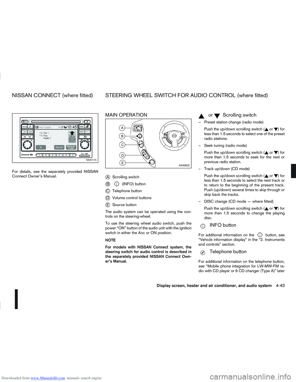
MAIN OPERATION
j
AScrolling switch
jB(INFO) button
jC Telephone button
jDVolume control buttons
jESource button
The audio system can be operated using the con-
trols on the steering-wheel.
To use the steering wheel audio switch, push the
power “ON” button of the audio unit with the ignition
switch in either the Acc or ON position.
NOTE
For models with NISSAN Connect system, the
steering switch for audio control is described in
the separately provided NISSAN Connect Own-
er’s Manual.
mormScrolling switch
– Preset station change (radio mode) Push the up/down scrolling switch (
or)for
less than 1.5 seconds to select one of the preset
radio stations.
– Seek tuning (radio mode) Push the up/down scrolling switch (
or)for
more than 1.5 seconds to seek for the next or
previous radio station.
– Track up/down (CD mode) Push the up/down scrolling switch (
or)for
less than 1.5 seconds to select the next track or
to return to the beginning of the present track.
Push (up/down) several times to skip through or
skip back the tracks.
– DISC change (CD mode — where fitted) Push the up/down scrolling switch (
or)for
more than 1.5 seconds to change the playing
disc.
mINFO button
For additional information on thebutton, see
“Vehicle information display” in the “2. Instruments
and controls” section.
mTelephone button
For additional information on the telephone button,
see “Mobile phone integration for LW-MW-FM ra-
dio with CD player or 6 CD changer (Type A)” later
NAA1115
NAA960Z
NISSAN CONNECT (where fitted) STEERING WHEEL SWITCH FOR AUDIO CONTROL (where fitted)
Display screen, heater and air conditioner, and audio system4-43
Page 159 of 297
Downloaded from www.Manualslib.com manuals search engine BLUETOOTH®MOBILE PHONE
FEATURE
WARNING
Whilst driving, using the mobile phone is ex-
tremely dangerous because it significantly im-
pairs your concentration and diminishes your re-
action capabilities to sudden changes on the
road, and it may lead to a fatal accident. This
applies to all phone call situations such as when
receiving an incoming call, during a phone con-
versation, when calling through the phone book
search, etc.
CAUTION
Certain country jurisdictions prohibit the use of
the mobile phone in the car without hands-free
support.
This chapter provides information about the NISSAN
hands-free phone system using a Bluetooth
®con-
nection. Bluetooth
®is a wireless radio communication stan-
dard. This system offers a hands-free facility for your
mobile telephone to enhance driving comfort.
NOTE
For models with NISSAN Connect system, see
the separately provided Owner’s Manual.
In order to use your mobile phone with the Blue-
tooth
®of the audio system, the mobile phone must
first be setup. For details, see “BLUETOOTH®
settings” later in this section. Once it has been
setup, the hands-free mode is automatically acti-
vated on the registered mobile phone (via Blue-
tooth
®) when it comes into range.
A notification message appears on the audio display
when the phone is connected, when an incoming
call is being received, as well as when a call is initi-
ated.
When a call is active, the audio system, microphone
(located in the ceiling in front of the rear view mir-
ror), and steering wheel switches enable hands-free
communication.
If the audio system is in use at the time, the radio,
CD, or AUX source mode will be muted and will stay
muted until the active call has ended.
The Bluetooth
®system may be not be able to con-
nect with your mobile phone for the following rea-
sons:
The mobile phone is too far away from the ve-
hicle.
The Bluetooth®mode on your mobile phone has
not been activated.
Your mobile phone has not been paired with the
Bluetooth®system of the audio unit.
The mobile phone does not support Bluetooth®
technology (BT Core v2.0).
NOTE
For models with NISSAN Connect (Audio with
Navigation system) see the separately pro-
vided Owner’s Manual.
For details, see your mobile phone’s Owner’s
Manual.
For assistance with your mobile phone inte-
gration, please visit your local NISSAN dealer.
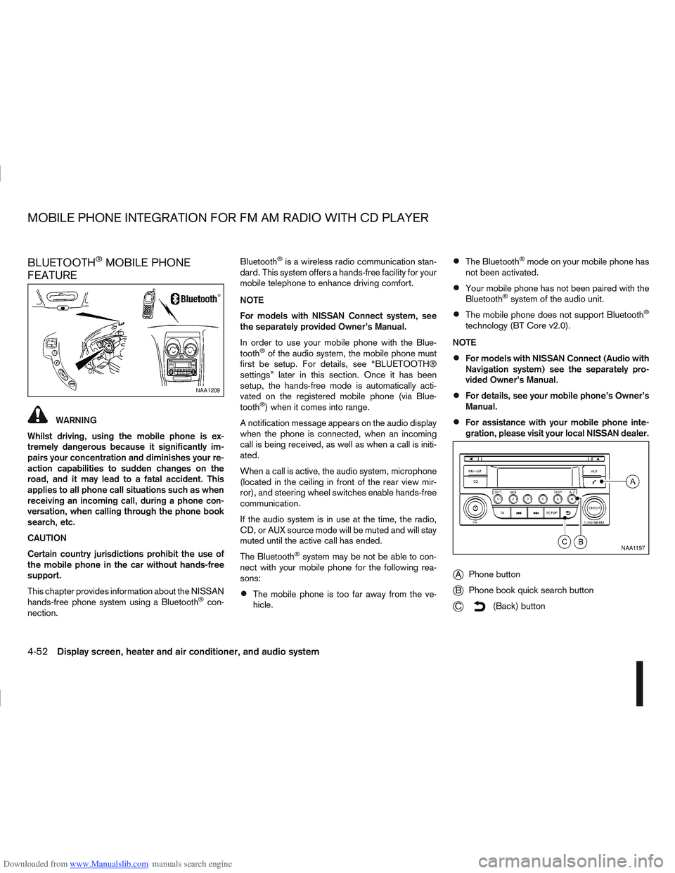
jA Phone button
jB Phone book quick search button
jC(Back) button
NAA1209
NAA1197
MOBILE PHONE INTEGRATION FOR FM AM RADIO WITH CD PLAYER
4-52Display screen, heater and air conditioner, and audio system
Page 169 of 297
Downloaded from www.Manualslib.com manuals search engine Driving your vehicle to fit the circumstances is es-
sential for your safety and comfort. As a driver, you
should be the one who knows best how to drive in
the given circumstances.
ENGINE COLD START PERIOD
Due to the higher engine speeds when the engine is
cold, extra caution must be exercised when select-
ing a gear during the engine warm-up period after
starting the engine.
LOADING LUGGAGE
Loads, their distribution and the attachment of equip-
ment (coupling devices, roof luggage carriers, etc.)
will change the driving characteristics of the vehicle
considerably. Driving style and speed must be ad-
justed accordingly.
DRIVING ON WET ROADS
Avoid starting off, accelerating and stopping sud-
denly.
Avoid sharp turns or lane changes.
Extra distance should be kept from the vehicle in
front.
When water covers the road surface in puddles,
small streams, etc, REDUCE SPEED to prevent
aquaplaning which will cause skidding and loss
of control. Worn tyres increase this risk.
DRIVING UNDER WINTER
CONDITIONS
Drive safely.
Avoid starting off, accelerating or stopping sud-
denly.
Avoid sharp turns or lane changes.
Avoid sudden steering actions.
Extra distance should be kept from the vehicle in
front.
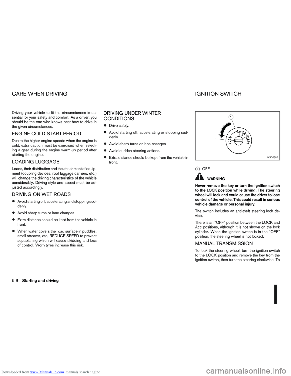
j1OFF
WARNING
Never remove the key or turn the ignition switch
to the LOCK position while driving. The steering
wheel will lock and could cause the driver to lose
control of the vehicle. This could result in serious
vehicle damage or personal injury.
The switch includes an anti-theft steering lock de-
vice.
There is an “OFF” position between the LOCK and
Acc positions, although it is not shown on the lock
cylinder. When the ignition switch is in the “OFF”
position, the steering wheel is not locked.
MANUAL TRANSMISSION
To lock the steering wheel, turn the ignition switch
to the LOCK position and remove the key from the
ignition switch, then turn the steering clockwise. To
NSD238Z
CARE WHEN DRIVING IGNITION SWITCH
5-6Starting and driving