rear view mirror NISSAN QASHQAI 2013 User Guide
[x] Cancel search | Manufacturer: NISSAN, Model Year: 2013, Model line: QASHQAI, Model: NISSAN QASHQAI 2013Pages: 297, PDF Size: 4.09 MB
Page 112 of 297
Downloaded from www.Manualslib.com manuals search engine Do not use the Around View Monitor with the
outside mirror in the stored position, and
make sure that the back door is securely
closed when operating the vehicle using the
Around View Monitor.
The distance between objects viewed on the
Around View Monitor differs from the actual
distance.
The cameras are installed above the front
grille, the outside mirrors and above the rear
number plate. Do not put anything on or cover
the cameras.
When washing the vehicle with high-pressure
water, be sure not to spray it around the cam-
eras. Otherwise, water may enter the camera
unit causing water condensation on the lens,
a malfunction, fire or an electric shock.
Do not strike the cameras. They are precision
instruments. Doing so could cause a malfunc-
tion or cause damage resulting in a fire or an
electric shock.
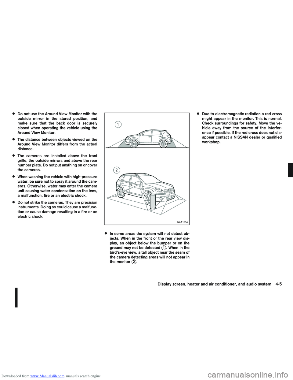
In some areas the system will not detect ob-
jects. When in the front or the rear view dis-
play, an object below the bumper or on the
ground may not be detected
j1 . When in the
bird’s-eye view, a tall object near the seam of
the camera detecting areas will not appear in
the monitor
j2.
Due to electromagnetic radiation a red cross
might appear in the monitor. This is normal.
Check surroundings for safety. Move the ve-
hicle away from the source of the interfer-
ence if possible. If the red cross does not dis-
appear contact a NISSAN dealer or qualified
workshop.
NAA1234
Display screen, heater and air conditioner, and audio system4-5
Page 114 of 297
Downloaded from www.Manualslib.com manuals search engine In R (Reverse) gear rear view and bird’s-eye viewj2 are shown. The view on the screen on the
passenger’s side switches to the front side view
j4 when the
Push the
back to rear view and bird’s-eye view
j2.
Pushing the CAMERA button
When the
View Monitor operates and the front view and
bird’s-eye view are displayed
j1.
The front view and bird’s-eye view are displayedj1 . The view on the screen on the passenger’s
side switches to the front-side view when the
j3 . Pushing the
Monitor off.
To switch the driver’s side screen between front
view and rear view use the gear selector lever.
GUIDE LINES
WARNING
The distance guide line and the vehicle width
line should be used as a reference only when
the vehicle is on a paved, level surface. The
distance viewed on the monitor is for refer-
ence only and may be different than the ac-
tual distance between the vehicle and dis-
played objects.
Use the displayed lines and the bird’s-eye
view as a reference. The lines and the bird’s- eye view are greatly affected by the number
of occupants, fuel level, vehicle position, road
condition and road grade.
If the tyres are replaced with different sized
tyres, the predictive course line and the bird’s-
eye view may be displayed incorrectly.
When driving the vehicle up a hill, objects
viewed in the monitor are further than they
appear. When driving the vehicle down a hill,
objects viewed in the monitor are closer than
they appear. Use the mirrors or actually look
to properly judge distances to other objects.
The vehicle width and predictive course lines
are wider than the actual width and course.
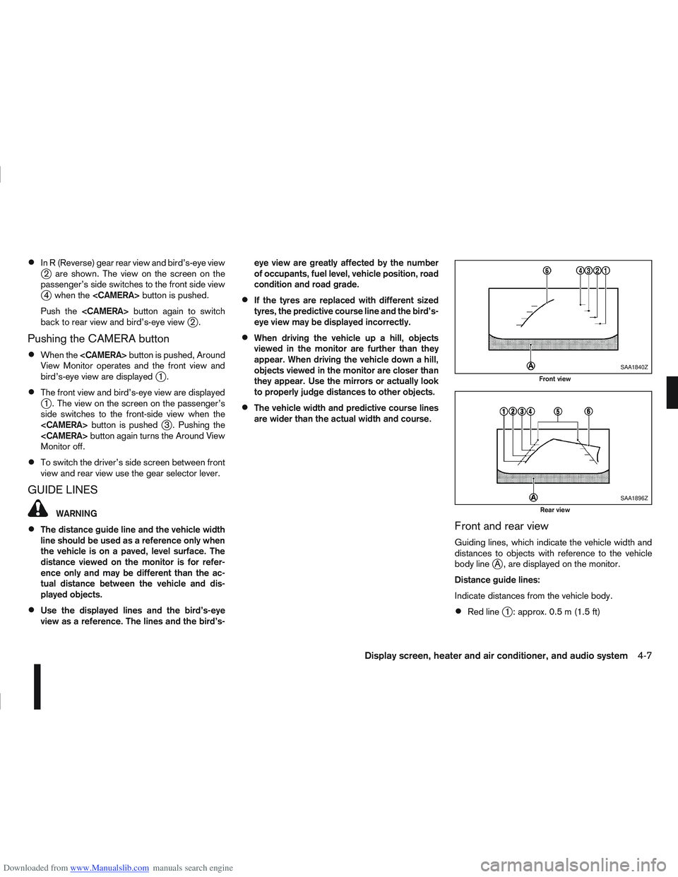
Front and rear view
Guiding lines, which indicate the vehicle width and
distances to objects with reference to the vehicle
body line
jA , are displayed on the monitor.
Distance guide lines:
Indicate distances from the vehicle body.
Red linej1 : approx. 0.5 m (1.5 ft)
SAA1840Z
Front view
SAA1896Z
Rear view
Display screen, heater and air conditioner, and audio system4-7
Page 115 of 297
Downloaded from www.Manualslib.com manuals search engine Yellow linej2 :approx.1m(3ft)
Green linej3 :approx.2m(7ft)
Green linej4 :approx.3m(10ft)
Vehicle width guide lines
j5:
Indicate the vehicle width when reversing.
Predictive course lines
j6:
Indicate the predictive course when operating the
vehicle. The predictive course lines will be displayed
on the monitor when the steering wheel is turned.
The predictive course lines will move depending on
how much the steering wheel is turned and will not
be displayed while the steering wheel is in the neu-
tral position.
The front view will not be displayed when the vehicle
speed is above 10 km/h (6 MPH).
WARNING
The distance between objects viewed in the
rear view differs from actual distance because
a wide-angle lens is used. Objects in the rear
view will appear visually opposite than when
viewed in the rear view and outside mirrors.
On a snow-covered or slippery road, there
may be a difference between the predictive
course line and the actual course line.
If the battery is disconnected or becomes dis-
charged, the predictive course lines may be
displayed incorrectly. If this occurs visit a
NISSAN dealer or qualified workshop.
If predictive course lines are displayed incor-
rectly visit a NISSAN dealer or qualified work-
shop.
The displayed lines on the rear view will ap-
pear slightly off to the right because the rear
view camera is not installed in the rear centre
of the vehicle.
NOTE
When the monitor displays the front view and the
steering wheel turns about 90 degrees or less
from the neutral position, both the right and left
predictive course lines
j6 are displayed. When
the steering wheel turns about 90 degrees or
more, a line is displayed only on the opposite
side of the turn.
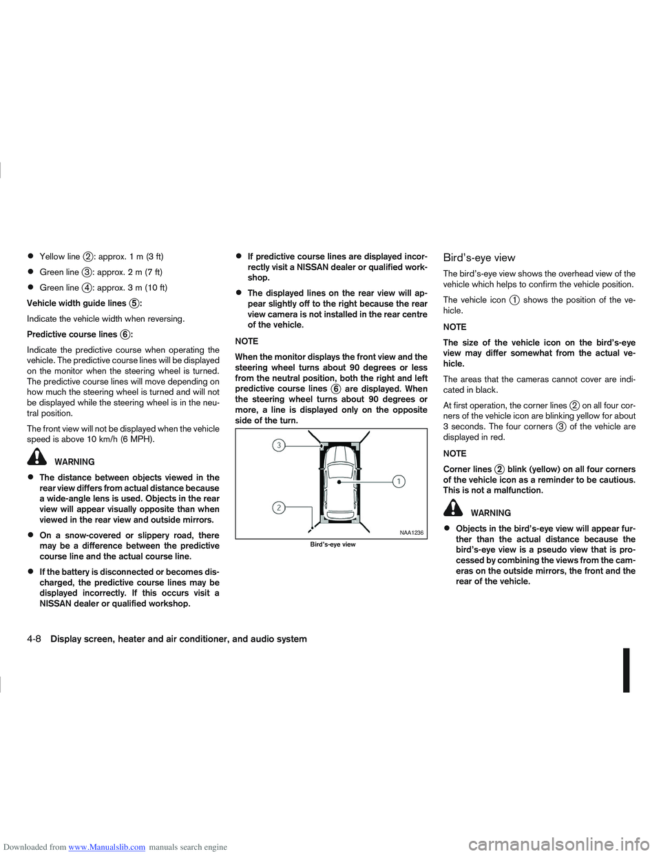
Bird’s-eye view
The bird’s-eye view shows the overhead view of the
vehicle which helps to confirm the vehicle position.
The vehicle icon
j1 shows the position of the ve-
hicle.
NOTE
The size of the vehicle icon on the bird’s-eye
view may differ somewhat from the actual ve-
hicle.
The areas that the cameras cannot cover are indi-
cated in black.
At first operation, the corner lines
j2 on all four cor-
ners of the vehicle icon are blinking yellow for about
3 seconds. The four corners
j3 of the vehicle are
displayed in red.
NOTE
Corner lines
j2 blink (yellow) on all four corners
of the vehicle icon as a reminder to be cautious.
This is not a malfunction.
WARNING
Objects in the bird’s-eye view will appear fur-
ther than the actual distance because the
bird’s-eye view is a pseudo view that is pro-
cessed by combining the views from the cam-
eras on the outside mirrors, the front and the
rear of the vehicle.NAA1236
Bird’s-eye view
4-8Display screen, heater and air conditioner, and audio system
Page 116 of 297

Downloaded from www.Manualslib.com manuals search engine Tall objects, such as a kerb or vehicle, may be
misaligned or not displayed at the seam of
the views.
Objects that are above the camera cannot be
displayed.
The view for the bird’s-eye view may be mis-
aligned when the camera position alters.
A line on the ground may be misaligned and is
not seen as being straight at the seam of the
views. The misalignment will increase as the
line proceeds away from the vehicle.
*: For the Right-Hand Drive (RHD) models, the screen layout will be opposite.
Front-side view
CAUTION
The actual distance to objects may differ from
the distance shown. Guiding lines:
Guiding lines that indicate the approximate width
and the front end of the vehicle are displayed on the
monitor.
The front-of-vehicle line
j1 shows the front part of
the vehicle.
The side-of-vehicle line
j2 shows the vehicle width
including the outside mirror.
The extensions
j3 of both the frontj1 and sidej2
lines are shown with a green dotted line.
DIFFERENCE BETWEEN PREDICTIVE
AND ACTUAL DISTANCES
The distance guide line and the vehicle width guide
line on the front and the rear view should be used as
a reference only when the vehicle is on a level, paved
surface. The distance viewed on the monitor is for
reference only and may be different than the actual
distance between the vehicle and displayed objects.
Moving to a steep uphill
When moving the vehicle up a hill, the distance guide
lines and the vehicle width guide lines are shown
closer than the actual distance. For example, the
display shows 1 m (3 ft) to the place
jA , but the
actual1m(3ft)d istance on the hill is the placejB.
Note that any object on the hill is viewed in the moni-
tor further than it appears.
NAA1237
Front–side view, Left-Hand Drive (LHD) models*NAA1238
Display screen, heater and air conditioner, and audio system4-9
Page 152 of 297
Downloaded from www.Manualslib.com manuals search engine Bluetooth®is a wireless radio communication stan-
dard. This system offers a hands-free facility for your
mobile telephone to enhance driving comfort.
NOTE
For models with NISSAN Connect system, see
the separately provided Owner’s Manual.
In order to use your mobile phone with the Blue-
tooth
®of the audio system, the mobile phone must
first be set-up. For details, see “Hands-free tele-
phone setup” later in this section. Once it has been
set-up, the hands-free mode is automatically acti-
vated on the registered mobile phone (via Blue-
tooth
®) when it comes into range.
A notification message on the audio display comes
on when the phone is connected, when an incoming
call is being received as well as when a call is initi-
ated.
When a call is active, the audio system, microphone
(located in the ceiling in front of the rear view mirror)
and the steering wheel switches enable hands-free
communication.
If the audio system is being used at the time, the
radio or CD mode will be muted and will stay muted
until the active call has ended.
If the Bluetooth
®system is unable to connect with
your mobile phone, this may occur because:
The mobile phone is too far away from the ve-
hicle.
The Bluetooth®mode on your mobile phone has
not been activated.
Your mobile phone has not been paired with the
Bluetooth®system of the audio unit.
The mobile phone does not support Bluetooth®
technology (BT Core v1.2, Hands Free Profile
v1.0 and Object Push Profile v1.0).
NOTE
For details, see your mobile phone’s Owner’s
Manual.
For assistance with your mobile phone inte-
gration, please visit your local NISSAN dealer.
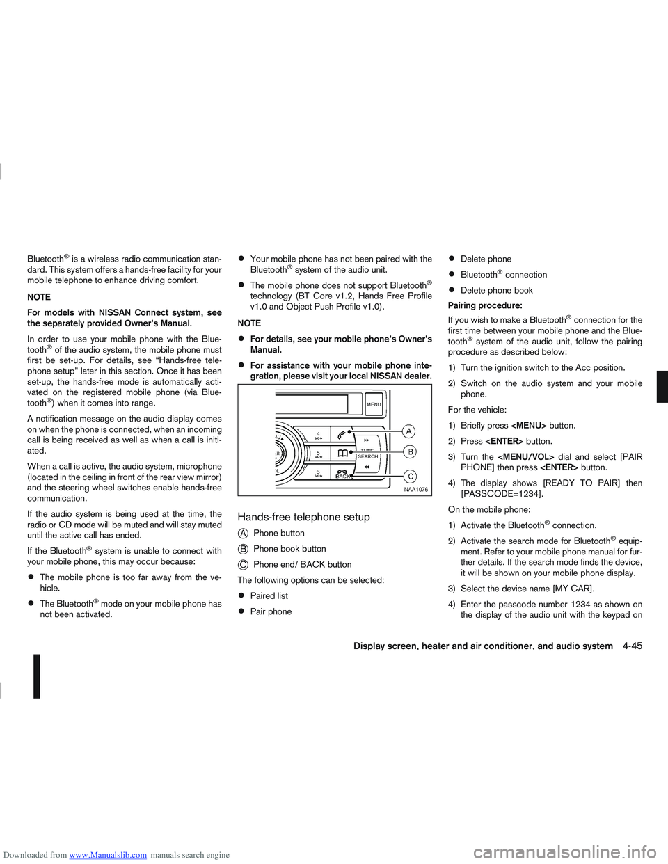
Hands-free telephone setup
j
A Phone button
jB Phone book button
jC Phone end/ BACK button
The following options can be selected:
Paired list
Pair phone
Delete phone
Bluetooth®connection
Delete phone book
Pairing procedure:
If you wish to make a Bluetooth
®connection for the
first time between your mobile phone and the Blue-
tooth
®system of the audio unit, follow the pairing
procedure as described below:
1) Turn the ignition switch to the Acc position.
2) Switch on the audio system and your mobile phone.
For the vehicle:
1) Briefly press
Page 158 of 297
Downloaded from www.Manualslib.com manuals search engine If necessary, turn the
lect the correct name.
5) Press the
(phone) button in or-
der to dial the number.
Calling via voice tag:
If your mobile phone supports voice recognition, it is
possible to make a call via the voice tag instead of
manual selection, provided the name and number of
your contact has been previously marked and stored
in the phone book of your mobile phone. For details,
see the mobile phone manufacturer’s owner’s
manual.
In order to dial via a voice tag, proceed as follows:
1) Press the
(phone) button for more than 2 sec-
onds.
2) The display shows [SPEAK NOW].
3) Give your voice tag. Say the voice tag clearly and normally in the di-
rection of the microphone (located in ceiling in
front of the rear view mirror).
4) If the voice tag is correct, the phone system will dial the corresponding number.
Make a call via speed dial:
To make a speed dial call using one of the assigned
preset buttons, proceed as follows:
1) Press the
(phone) button briefly.
2) Press the corresponding preset button (1–6). Alternatively, you can select the corresponding
preset number by turning the
instead of pressing the preset button.
Receiving a call
When receiving an incoming call, the display will
show the caller identification (or [NO NUMBER])
and you can:
answer the call by pressing briefly on the(phone) button.
end the call after the conversation by pressing
thebutton.
reject the call by pressing thebutton.
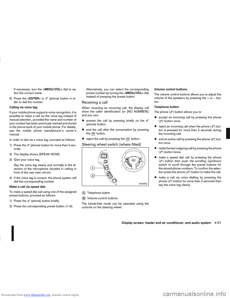
Steering wheel switch (where fitted)
j
A Telephone button
jB Volume control buttons
The hands-free mode can be operated using the
controls on the steering wheel. Volume control buttons:
The volume control buttons allows you to adjust the
volume of the speakers by pressing the + or – but-
ton.
Telephone button:
The phone (
) button allows you to:
accept an incoming call by pressing the phone
() button once.
reject an incoming call when the phone () but-
ton is pressed for more than 2 seconds during
the incoming call.
end an active call by pressing the phone () but-
ton once.
redial the last outgoing call by pressing the phone
() button twice.
make a speed dial call by pressing the phone
() button then push the scrolling (up/down)
switch to scroll through the preset buttons for
the stored phone numbers. To confirm the selec-
tion press the phone (
) button to make the call.
make a call via voice dialling by pressing the
phone () button for more than 2 seconds then
say the voice tag clearly.NAA998Z
Display screen, heater and air conditioner, and audio system4-51
Page 187 of 297
![NISSAN QASHQAI 2013 User Guide Downloaded from www.Manualslib.com manuals search engine – [Total Saving]
Estimated CO2 exhaust emissions pre-
vented.
Time that the engine has been stopped by
the Stop/Start System.
NOTE
The [Total NISSAN QASHQAI 2013 User Guide Downloaded from www.Manualslib.com manuals search engine – [Total Saving]
Estimated CO2 exhaust emissions pre-
vented.
Time that the engine has been stopped by
the Stop/Start System.
NOTE
The [Total](/img/5/56763/w960_56763-186.png)
Downloaded from www.Manualslib.com manuals search engine – [Total Saving]
Estimated CO2 exhaust emissions pre-
vented.
Time that the engine has been stopped by
the Stop/Start System.
NOTE
The [Total Saving] values cannot be reset
and show accumulated Stop/Start System
information since the vehicle was built.Ultrasonic sensors
jA , fitted in the vehicle’s rear
bumper, measure the distance between the vehicle
and an obstacle when reversing. When reverse gear
is engaged a beeping sound is heard. The frequency
of the beeps will increase the closer you come to
the obstacle until, the sound becomes a constant
beep when, the vehicle is approximately 30 cm (12
in) from the obstacle.
NOTE
This system is intended as an aid to reversing,
to be used in conjunction with your rear view
mirror.
Make sure that the ultrasonic sensors are not
obscured (by dirt, mud, snow, etc.). The Four Wheel Drive (4WD) system is used to
select 2WD, AUTO, or LOCK depending on the
driving conditions.
The Four Wheel Drive (4WD) system controls the
coupling operation. Turn the control (located on the
centre console) to select each mode: 2WD, AUTO
or LOCK depending on the driving conditions.
AUTO: Turn the 4WD mode control to the neutral
(AUTO) position and the Four-Wheel Drive (4WD)
AUTO indicator light
on the combination meter
illuminates.
2WD: Turn the control clockwise to the 2WD posi-
tion.
LOCK: When the control is turned anticlockwise to
the LOCK position, it springs back to the AUTO
position when released. The 4WD LOCK mode in-
dicator light
illuminates on the combination
meter, to show LOCK mode is engaged. To disen-
gage LOCK mode, turn the control anticlockwise
again to the LOCK position and release. The 4WD
LOCK mode indicator light will go out.
NSD300ZNSD297Z
ULTRASONIC PARKING SENSOR
(where fitted) FOUR-WHEEL DRIVE (4WD)
(where fitted)
5-24Starting and driving
Page 227 of 297
Downloaded from www.Manualslib.com manuals search engine Occasionally remove loose dust from the interior
trim, plastic parts and seats using a vacuum cleaner
or soft bristled brush. Wipe the vinyl and leather sur-
faces with a clean, soft cloth dampened in mild soap
solution, then wipe clean with a dry, soft cloth.
Regular care and cleaning is required in order to
maintain the appearance of the leather.
Before using any fabric protector, read the manu-
facturer’s recommendations. Some fabric protec-
tors contain chemicals that may stain or bleach the
seat material.
Use a soft cloth dampened only with water to clean
the meter and gauge lens covers.
CAUTION
Never use benzine, thinner or any similar ma-
terial.
Small dirt particles can be abrasive and dam-
aging to leather surfaces and should be re-
moved promptly. Do not use saddle soap, car
waxes, polishes, oils cleaning fluids, solvents,
detergents or ammonia based cleaners as
they may damage the leather’s natural finish.
Never use fabric protectors unless recom-
mended by the manufacturer.
Do not use glass or plastic cleaner on meter
or gauge lens covers. It may damage the lens
covers.
MONITOR DISPLAY’S MAINTENANCE
(where fitted)
To clean the display screen, first turn the ignition
off and wipe it with a dry soft cloth.
Never use a rough cloth, alcohol, benzine, thin-
ner, any kind of solvent, or paper tissues with
chemical cleaning agent. They would scratch or
deteriorate the panel.
Do not splash any liquid such as water or car fra-
grance on the display. Contact with liquid will
cause the system to malfunction and damage
the hardware.
In case of extreme stain, use a small amount of
neutral detergent with a soft cloth. Never soak
the screen display with water detergent.
FLOOR MATS
The use of NISSAN floor mats can extend the life of
your vehicle carpet and make it easier to clean the
interior. Regardless of what mats are used, be sure
they are fitted for your vehicle and are properly posi-
tioned in the foot well to prevent interference with
pedal operation. Mats should be maintained with
regular cleaning and replaced if they become exces-
sively worn.
CLEANING GLASS
Use glass cleaner to remove smoke and dust film
from the glass surfaces. It is normal for glass to
become coated with a film after the vehicle is parked
in the hot sun. Glass cleaner and a soft cloth will
easily remove this film.CAUTION
When cleaning the inside of the windows, do not
use sharp-edged tools, abrasive cleaners or chlo-
rine-based disinfectant cleaners. They could
damage elements in the rear windows (such as
the window defogger).
Inside rear-view mirror (Automatic
anti-dazzling, where fitted)
Use a soft cloth dampened only with water to clean
the automatic anti-dazzling inside rear view mirror
(where fitted).
CAUTION
Do not use glass cleaner. Doing so will reduce
the sensitivity of the sensor, resulting in improper
operation.
PLASTIC PARTS
Plastic parts can be cleaned with a mild soap solu-
tion. If the dirt cannot be easily removed, use a plas-
tic cleaner. Do not use any solvents.
SEAT BELTS
WARNING
Do not allow wet seat belts to roll up in the
retractor.
Never use bleach, dye or chemical solvents to
clean the seat belts, since these materials
may severely weaken the seat belt webbing.
CLEANING INTERIOR
7-4Appearance and care
Page 283 of 297
Downloaded from www.Manualslib.com manuals search engine – Checking handbrake ..................................................... 8-15
– Handbrake lever ............................................................ 3-16
– Trailer brakes ................................................................ 5-36
Brightness control ............................................................... 2-16C
C-View® ........................................................................\
..... 2-36
– Sunshade (Reinitialisation procedure) ............................ 2-37
– Sunshade operation ...................................................... 2-36
Capacities and recommended fuel/lubricants ......................... 9-2
– Fuel recommendation ...................................................... 9-5
Car phone or CB radio ........................................................ 4-44
Care when driving ................................................................. 5-6
Changing
– Changing engine coolant ................................................. 8-6
– Changing engine oil ......................................................... 8-9
– Changing engine oil filter ............................................... 8-11
– Changing tyres and wheels ........................................... 8-33
Checking
– Checking brake pedal ................................................... 8-15
– Checking engine coolant level ......................................... 8-6
– Checking engine oil level ................................................. 8-8
– Checking handbrake ..................................................... 8-15
Child restraints .................................................................... 1-18
– 5-seater ........................................................................\
. 1-20
– 7-seater ........................................................................\
. 1-20
– Anchor points ................................................................ 1-28
– Installation on front passenger seat ................................ 1-23
– Installation on rear seats ................................................ 1-24
– Top tether strap for child restraint .................................. 1-27
Child safety ........................................................................\
... 1-8
Cleaning
– Alloy wheels .................................................................... 7-3
– Chrome parts .................................................................. 7-3
– Exterior ........................................................................\
.... 7-2 – Glass ....................................................................... 7-3, 7-4
– Interior ........................................................................\
.... 7-4
– Plastic parts .................................................................... 7-4
– Rear-view camera lens .................................................... 7-3
– Removing spots ............................................................... 7-2
– Underbody ...................................................................... 7-3
Clutch fluid ........................................................................\
.. 8-15
Cold weather driving ........................................................... 5-42
Console box ........................................................................\
2-32
Continuously variable transmission
– Continuously variable transmission fluid ......................... 8-14
– Driving with continuously variable transmission (Models with
manual shift) .................................................................. 5-14
– Driving with continuously variable transmission (Models without manual shift) .................................................................. 5-17
Coolant
– Changing engine coolant ................................................. 8-6
– Checking engine coolant level ......................................... 8-6
– Engine coolant ............................................................... 5-43
– Engine coolant temperature gauge ................................... 2-2
– Engine cooling system ..................................................... 8-6
Corrosion protection .................................................... 5-43, 7-5
– Environmental factors ...................................................... 7-5
Cruise control ............................................................ 2-21, 5-29
Cruise control system operations ......................................... 5-30
D
Defogger switch
– Outside mirror defogger ................................................ 2-24
– Rear window defogger .................................................. 2-23
Diesel particulate filter (DPF) ................................................. 5-5
Diesel particulate filter (DPF) warning light ............................. 2-4
Difference between predictive and actual distances ............... 4-9
Dimensions ........................................................................\
... 9-8
10-2Index
Page 285 of 297
Downloaded from www.Manualslib.com manuals search engine Four-wheel drive (4WD) ...................................................... 5-24
– Driving four-wheel drive (4WD) safely ............................ 5-27
– Four-wheel drive (4WD) model (Tyres) .......................... 8-33
– Four-wheel drive mode indicator light ............................. 5-27
– Four-wheel drive warning light ....................................... 5-26
Front passenger air bag deactivation system ....................... 1-17
Front passenger air bag indicator light ................................. 1-17
Fuel
– Bleeding the fuel system ................................................ 8-14
– Capacities and recommended fuel/lubricants ................... 9-2
– Draining water (Fuel filter) .............................................. 8-13
– Fuel filter (Diesel engine models) ................................... 8-13
– Fuel gauge ...................................................................... 2-2
– Fuel recommendation ...................................................... 9-5
Fuel filler lid
– Cap ........................................................................\
....... 3-15
– Opener lever ................................................................. 3-15
Fuses ........................................................................\
.......... 8-23
– Engine compartment ...................................................... 8-24
– Passenger compartment ................................................ 8-23G
Gauges
– Engine coolant temperature gauge ................................... 2-2
– Fuel gauge ...................................................................... 2-2
– Meters and gauges .......................................................... 2-2
Glove box ........................................................................\
.... 2-31
Guide lines ........................................................................\
.... 4-7
H
Handbrake lever .................................................................. 3-16
Hazard warning flasher switch ............................................. 2-28 Head restraint
– Active head restraints ...................................................... 1-6
– Adjustment ...................................................................... 1-5
Headlight
– Headlight aiming control switch ..................................... 2-27
– Headlight and turn signal switch .................................... 2-24
– Headlight cleaner .......................................................... 2-28
– Headlight switch ............................................................ 2-24
– Headlights (bulb replacement) ....................................... 8-26
– Replacement (bulb) ....................................................... 8-25
– Turn signal switch .......................................................... 2-26
– Xenon ........................................................................\
... 2-24
Heated seats ....................................................................... 2-29
Heater and air conditioner ................................................... 4-12
Horn ........................................................................\
........... 2-29
How to adjust the screen view ............................................. 4-11
I
Ignition
– Ignition knob (Intelligent Key equipped models) ................ 5-8
– Ignition switch ................................................................. 5-6
Immobilizer
– NATS immobilizer radio approval number ....................... 9-10
– NISSAN Anti-Theft System (NATS) ............................... 3-13
Indicator lights ....................................................................... 2-3
Injured persons ..................................................................... 1-9
Inside rear-view mirror ......................................................... 3-17
Instrument and control layout
– LHD and RHD models ..................................................... 0-5
Integrated keyfob (remote control system) ............................. 3-3
– Battery replacement ...................................................... 8-19
– Ignition switch ................................................................. 5-6
– Keyfob operation failure ................................................... 3-6
– Locking the doors ............................................................ 3-5
– Setting the unlock mode .................................................. 3-4
10-4Index