rear view mirror NISSAN QASHQAI 2013 Owners Manual
[x] Cancel search | Manufacturer: NISSAN, Model Year: 2013, Model line: QASHQAI, Model: NISSAN QASHQAI 2013Pages: 297, PDF Size: 4.09 MB
Page 8 of 297
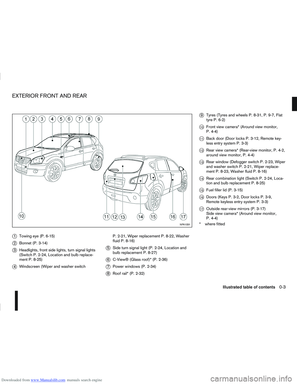
Downloaded from www.Manualslib.com manuals search engine j1Towing eye (P. 6-15)
j2Bonnet (P. 3-14)
j3Headlights, front side lights, turn signal lights
(Switch P. 2-24, Location and bulb replace-
ment P. 8-25)
j4Windscreen (Wiper and washer switch P. 2-21, Wiper replacement P. 8-22, Washer
fluid P. 8-16)
j5
Side turn signal light (P. 2-24, Location and
bulb replacement P. 8-27)
j6C-View® (Glass roof)* (P. 2-36)
j7Power windows (P. 2-34)
j8Roof rail* (P. 2-32)
j9Tyres (Tyres and wheels P. 8-31, P. 9-7, Flat
tyre P. 6-2)
j10Front view camera* (Around view monitor,
P. 4-4)
j11Back door (Door locks P. 3-12, Remote key-
less entry system P. 3-3)
j12Rear view camera* (Rear-view monitor, P. 4-2,
around view monitor, P. 4-4)
j13Rear window (Defogger switch P. 2-23, Wiper
and washer switch P. 2-21, Wiper replace-
ment P. 8-23, Washer fluid P. 8-16)
j14Rear combination light (Switch P. 2-24, Loca-
tion and bulb replacement P. 8-25)
j15Fuel filler lid (P. 3-15)
j16Doors (Keys P. 3-2, Door locks P. 3-9,
Remote keyless entry system P. 3-3)
j17Outside rear-view mirrors (P. 3-17)
Side view camera* (Around view monitor,
P. 4-4)
* where fitted
NPA1091
EXTERIOR FRONT AND REAR
Illustrated table of contents0-3
Page 10 of 297
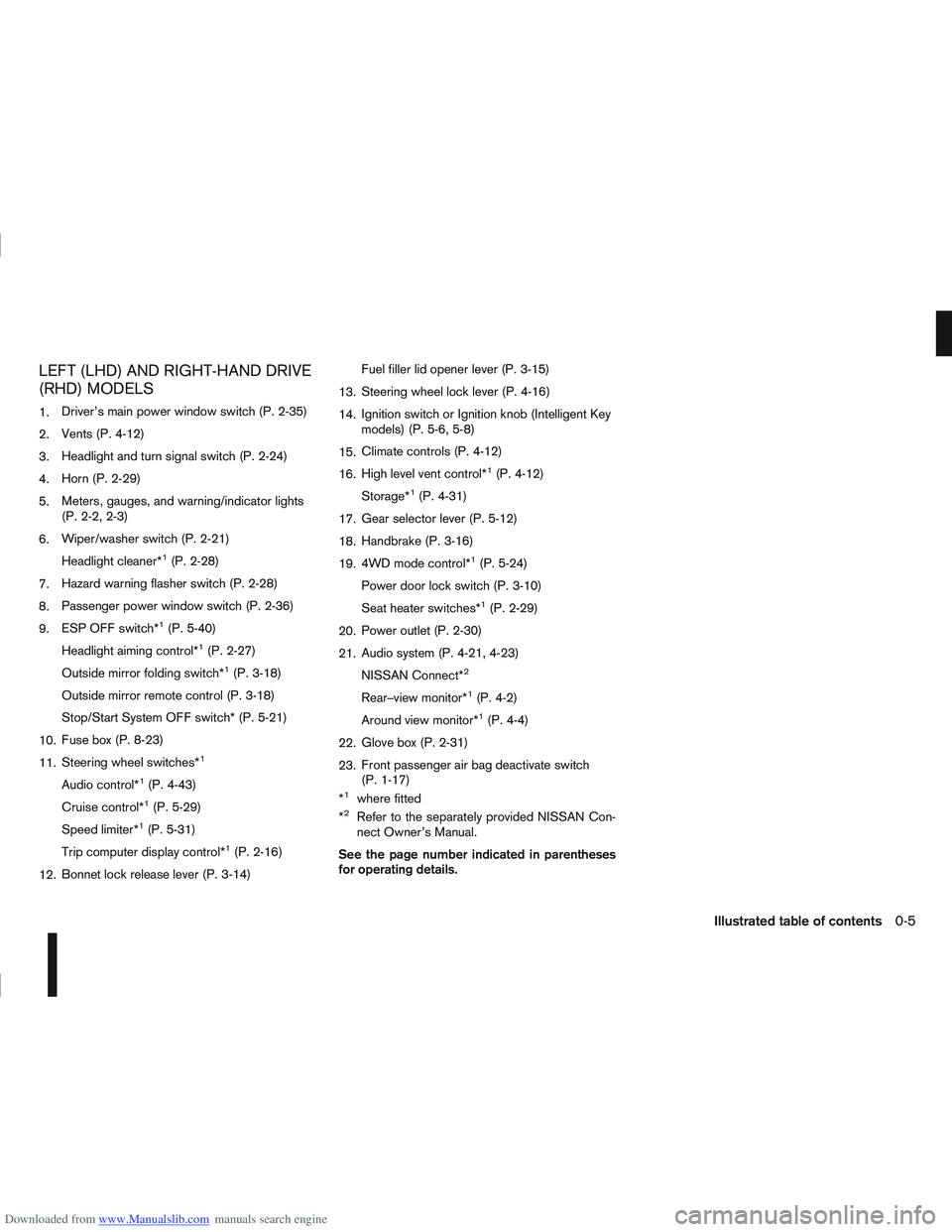
Downloaded from www.Manualslib.com manuals search engine LEFT (LHD) AND RIGHT-HAND DRIVE
(RHD) MODELS
1.Driver’s main power window switch (P. 2-35)
2. Vents (P. 4-12)
3. Headlight and turn signal switch (P. 2-24)
4. Horn (P. 2-29)
5. Meters, gauges, and warning/indicator lights
(P. 2-2, 2-3)
6. Wiper/washer switch (P. 2-21)
Headlight cleaner*
1(P. 2-28)
7. Hazard warning flasher switch (P. 2-28)
8. Passenger power window switch (P. 2-36)
9. ESP OFF switch*
1(P. 5-40)
Headlight aiming control*
1(P. 2-27)
Outside mirror folding switch*
1(P. 3-18)
Outside mirror remote control (P. 3-18)
Stop/Start System OFF switch* (P. 5-21)
10. Fuse box (P. 8-23)
11. Steering wheel switches*
1
Audio control*1(P. 4-43)
Cruise control*
1(P. 5-29)
Speed limiter*
1(P. 5-31)
Trip computer display control*
1(P. 2-16)
12. Bonnet lock release lever (P. 3-14) Fuel filler lid opener lever (P. 3-15)
13. Steering wheel lock lever (P. 4-16)
14. Ignition switch or Ignition knob (Intelligent Key
models) (P. 5-6, 5-8)
15. Climate controls (P. 4-12)
16. High level vent control*
1(P. 4-12)
Storage*
1(P. 4-31)
17. Gear selector lever (P. 5-12)
18. Handbrake (P. 3-16)
19. 4WD mode control*
1(P. 5-24)
Power door lock switch (P. 3-10)
Seat heater switches*
1(P. 2-29)
20. Power outlet (P. 2-30)
21. Audio system (P. 4-21, 4-23)
NISSAN Connect*
2
Rear–view monitor*1(P. 4-2)
Around view monitor*
1(P. 4-4)
22. Glove box (P. 2-31)
23. Front passenger air bag deactivate switch
(P. 1-17)
*
1where fitted
*2Refer to the separately provided NISSAN Con-
nect Owner’s Manual.
See the page number indicated in parentheses
for operating details.
Illustrated table of contents0-5
Page 49 of 297
Downloaded from www.Manualslib.com manuals search engine 2Instruments and controls
Instruments and controls
Meters and gauges .................................................. 2-2
Speedometer...................................................... 2-2
Fuel gauge ......................................................... 2-2
Tachometer ........................................................ 2-2
Engine coolant temperature gauge ...................... 2-2
Warning/indicator lights and audible reminders ........ 2-3 Checking bulbs .................................................. 2-3
Warning lights .................................................... 2-3
Indicator lights .................................................... 2-7
Audible reminders............................................... 2-9
Vehicle information display ....................................... 2-11 Warnings and alerts............................................ 2-12
Odometer/twin trip odometer .............................. 2-16
Brightness control .............................................. 2-16
Trip computer ..................................................... 2-16
Settings menu .................................................... 2-18
Cruise control/Speed limiter indicator (where
fitted).................................................................. 2-21
Wiper and washer switch ........................................ 2-21 Windscreen ........................................................ 2-22
Rear window ...................................................... 2-23
Defogger switch ...................................................... 2-23 Rear window defogger ....................................... 2-23
Outside mirror defogger (where fitted) ................ 2-24
Headlight and turn signal switch............................... 2-24 Xenon headlights (where fitted) ........................... 2-24
Headlight switch ................................................. 2-24
Turn signal switch ............................................... 2-26
Fog light switch ....................................................... 2-26 Front fog light (where fitted) ................................ 2-26 Rear fog light ...................................................... 2-27
Headlight aiming control .......................................... 2-27 Headlight aiming control switch (where fitted) ..... 2-27
Automatic aiming control (xenon headlights) ........ 2-27
Headlight cleaner (where fitted) ............................... 2-28
Hazard warning flasher switch ................................. 2-28
Horn ........................................................................\
2-29
Seat heating (where fitted) ....................................... 2-29
Power outlet ............................................................ 2-30
Storage ................................................................... 2-31 Storage trays ...................................................... 2-31
Glove box ........................................................... 2-31
Console box ....................................................... 2-32
Cup holders ....................................................... 2-32
Bottle holder ....................................................... 2-32
Map pocket (where fitted) ................................... 2-32
Seat pocket (where fitted)................................... 2-32
Roof rail (where fitted) ........................................ 2-32
Rear parcel shelf (where fitted) ................................ 2-33
Tonneau cover (where fitted).................................... 2-33
Windows ................................................................. 2-34 Power windows .................................................. 2-34
C-View® glass roof (where fitted) ............................ 2-36 Sunshade operation ............................................ 2-36
System reinitialisation.......................................... 2-37
Interior lights ............................................................ 2-37 Front Room light ................................................. 2-37
Map lights (where fitted) ..................................... 2-38
Rear room/reading light ...................................... 2-38
Luggage compartment light ................................ 2-38
Page 73 of 297
Downloaded from www.Manualslib.com manuals search engine OUTSIDE MIRROR DEFOGGER
(where fitted)
The outside rear-view mirrors will be defogged when
the defogger switch is activated.
XENON HEADLIGHTS (where fitted)
WARNING
HIGH VOLTAGE
When xenon headlights are on, they produce
a high voltage. To prevent an electric shock,
never attempt to modify or disassemble. Al-
ways have your xenon headlights replaced at
an authorised NISSAN dealer or qualified
workshop.
Xenon headlights provide considerably more
light than conventional headlights. If they are
not correctly aimed, they might temporarily
blind an oncoming driver or the driver ahead
of you and cause a serious accident. If head-
lights are not aimed correctly, immediately
take your vehicle to a NISSAN dealer or quali-
fied workshop and have the headlights ad-
justed correctly.
When the xenon headlight is initially turned on, its
brightness or colour varies slightly. However, the
colour and brightness will soon stabilise.
The life of xenon headlights will be shortened by
frequent on-off operation. It is generally desir-
able not to turn off the headlights for short inter-
vals (for example, when the vehicle stops at a
traffic signal).
If the xenon headlight bulb is close to burning
out, the brightness will drastically decrease, the
light will start blinking, or the colour of the light will become reddish. If one or more of the above
signs occur, contact a NISSAN dealer or quali-
fied workshop.
NISSAN recommends you to consult the local regu-
lations concerning the use of lights.
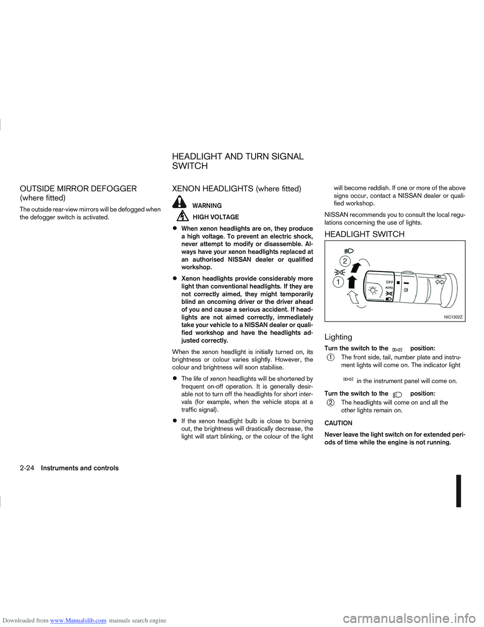
HEADLIGHT SWITCH
Lighting
Turn the switch to themposition:
j1 The front side, tail, number plate and instru- ment lights will come on. The indicator light
min the instrument panel will come on.
Turn the switch to the
mposition:
j2 The headlights will come on and all the other lights remain on.
CAUTION
Never leave the light switch on for extended peri-
ods of time while the engine is not running.
NIC1302Z
HEADLIGHT AND TURN SIGNAL
SWITCH
2-24Instruments and controls
Page 76 of 297
Downloaded from www.Manualslib.com manuals search engine tion and turn the fog light switch to thepositionj1 . The front fog lights and indicator light will come
on. For additional information, see “Warning/indica-
tor lights and audible reminders” earlier in this sec-
tion.
To turn the front fog lights off, turn the fog light
switch to the OFF position.
REAR FOG LIGHT
The rear fog light should only be used when visibility
is seriously reduced – generally, to less than 100 m
(328 ft).
TypejA (without front fog lights)
To turn the rear fog light on:
1. Turn the headlight switch to the
position.
2. Turn the fog light switch to the
positionj1:
– The rear fog light and indicator light will come on
– The fog light switch will return to the “OFF” posi- tion ( —)
To turn the rear fog light off:
Turn the fog light switch to the
positionj1 again:
– The rear fog light and indicator light will switch off
– The fog light switch will return to the “OFF” posi- tion ( —) NOTE
If the headlight switch is turned from the
position, the rear fog light will switch off auto-
matically.
TypejB (with front fog lights)
To turn the rear fog light on:
1. Turn the headlight switch to the
orposition.
2. Turn the fog light switch to the
positionj2:
– The rear and front fog lights and both indicator lights will come on
– The fog light switch will return to the
positionj1
To turn the rear fog light off:
Turn the fog light switch to the
positionj2
again:
– The rear fog light and indicator light will switch off
– The fog light switch will return to the
position
NOTE
If the headlight switch is turned to the OFF posi-
tion, the rear fog light will switch off automati-
cally.
For additional information, see “Warning/indicator
lights and audible reminders” earlier in this section.
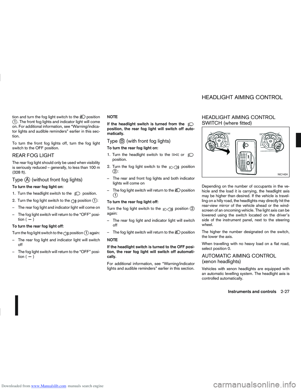
HEADLIGHT AIMING CONTROL
SWITCH (where fitted)
Depending on the number of occupants in the ve-
hicle and the load it is carrying, the headlight axis
may be higher than desired. If the vehicle is travel-
ling on a hilly road, the headlights may directly hit the
rear-view mirror of the vehicle ahead or the wind-
screen of an oncoming vehicle. The light axis can be
lowered using the switch located on the driver’s
side of the instrument panel, next to the steering
wheel.
The higher the number designated on the switch,
the lower the axis.
When travelling with no heavy load on a flat road,
select position 0.
AUTOMATIC AIMING CONTROL
(xenon headlights)
Vehicles with xenon headlights are equipped with
an automatic levelling system. The headlight axis is
controlled automatically.
NIC1424
HEADLIGHT AIMING CONTROL
Instruments and controls2-27
Page 88 of 297
Downloaded from www.Manualslib.com manuals search engine 3Pre-driving checks and adjustments
Pre-driving checks and adjustments
Keys ........................................................................\
3-2
NISSAN Anti-Theft System (NATS)* key ............. 3-2
Intelligent Key (where fitted)................................ 3-2
Key number ........................................................ 3-3
New keys ........................................................... 3-3
Emergency/mechanical key (Intelligent Key
models) .............................................................. 3-3
Integrated keyfob/remote control system .................. 3-3 Switching from Convenience mode to
Anti-hijack mode ................................................. 3-4
Using the remote keyless entry system ................ 3-5
Locking the doors ............................................... 3-5
Unlocking the doors ............................................ 3-5
Keyfob operation failure ...................................... 3-6
Intelligent Key system (where fitted) ......................... 3-6 Intelligent Key operating range ............................ 3-6
Using Intelligent Key system................................ 3-7
Locking/unlocking .............................................. 3-7
Starting the engine with the Intelligent Key .......... 3-8
Door locks ............................................................... 3-9 Super Lock system (RHD models) ...................... 3-9
Locking/unlocking with the key (vehicle dead
battery) ............................................................... 3-9 Inside door handle .............................................. 3-10
Power door lock switch ...................................... 3-10
Child safety lock — rear doors............................ 3-11
Back door lock ................................................... 3-12
Security system ....................................................... 3-13 Alarm system (where fitted) ................................ 3-13
NISSAN Anti-Theft System (NATS)..................... 3-13
Bonnet release ........................................................ 3-14
Fuel filler lid ............................................................. 3-15 Fuel filler lid opener lever .................................... 3-15
Fuel filler cap ...................................................... 3-15
Handbrake lever ...................................................... 3-16
Steering wheel......................................................... 3-16
Sun visors ............................................................... 3-17
Mirrors..................................................................... 3-17 Inside rear-view mirror ........................................ 3-17
Automatic anti-dazzling inside mirror (where
fitted).................................................................. 3-17
Outside rear-view mirrors.................................... 3-17
Vanity mirror ....................................................... 3-19
Page 104 of 297
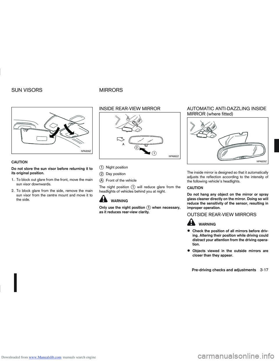
Downloaded from www.Manualslib.com manuals search engine CAUTION
Do not store the sun visor before returning it to
its original position.
1. To block out glare from the front, move the mainsun visor downwards.
2. To block glare from the side, remove the main sun visor from the centre mount and move it to
the side.
INSIDE REAR-VIEW MIRROR
j
1 Night position
j2Day position
jA Front of the vehicle
The night position
j1 will reduce glare from the
headlights of vehicles behind you at night.
WARNING
Only use the night position
j1 when necessary,
as it reduces rear-view clarity.
AUTOMATIC ANTI-DAZZLING INSIDE
MIRROR (where fitted)
The inside mirror is designed so that it automatically
adjusts the reflection according to the intensity of
the following vehicle’s headlights.
CAUTION
Do not hang any object on the mirror or spray
glass cleaner directly on the mirror. Doing so will
reduce the sensitivity of the sensor, resulting in
improper operation.
OUTSIDE REAR-VIEW MIRRORS
WARNING
Check the position of all mirrors before driv-
ing. Altering their position while driving could
distract your attention from the driving opera-
tion.
Objects viewed in the outside mirrors are
closer than they appear.
NPA839Z
NPA862Z
NPA829Z
SUN VISORS MIRRORS
Pre-driving checks and adjustments3-17
Page 105 of 297
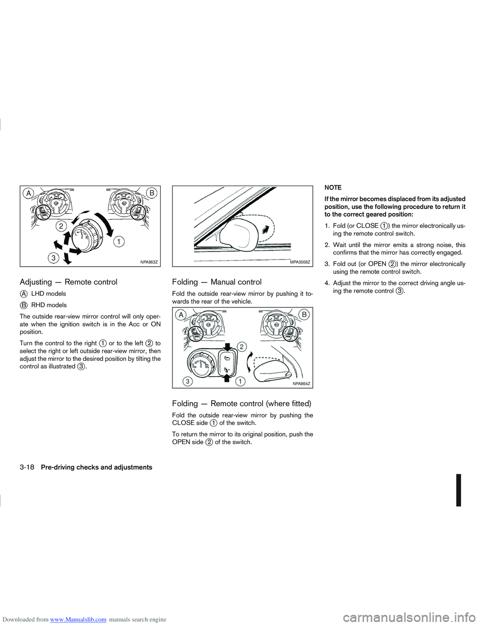
Downloaded from www.Manualslib.com manuals search engine Adjusting — Remote control
j
ALHD models
jB RHD models
The outside rear-view mirror control will only oper-
ate when the ignition switch is in the Acc or ON
position.
Turn the control to the right
j1 ortotheleftj2to
select the right or left outside rear-view mirror, then
adjust the mirror to the desired position by tilting the
control as illustrated
j3.
Folding — Manual control
Fold the outside rear-view mirror by pushing it to-
wards the rear of the vehicle.
Folding — Remote control (where fitted)
Fold the outside rear-view mirror by pushing the
CLOSE sidej1 of the switch.
To return the mirror to its original position, push the
OPEN side
j2 of the switch. NOTE
If the mirror becomes displaced from its adjusted
position, use the following procedure to return it
to the correct geared position:
1. Fold (or CLOSE
j1 ) the mirror electronically us-
ing the remote control switch.
2. Wait until the mirror emits a strong noise, this confirms that the mirror has correctly engaged.
3. Fold out (or OPEN
j2 ) the mirror electronically
using the remote control switch.
4. Adjust the mirror to the correct driving angle us- ing the remote control
j3.
NPA863ZMPA0008Z
NPA864Z
3-18Pre-driving checks and adjustments
Page 109 of 297
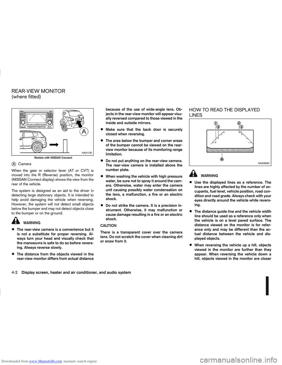
Downloaded from www.Manualslib.com manuals search engine jACamera
When the gear or selector lever (AT or CVT) is
moved into the R (Reverse) position, the monitor
(NISSAN Connect display) shows the view from the
rear of the vehicle.
The system is designed as an aid to the driver in
detecting large stationary objects. It is intended to
help avoid damaging the vehicle when reversing.
However, the system will not detect small objects
below the bumper and may not detect objects close
to the bumper or on the ground.
WARNING
The rear-view camera is a convenience but it
is not a substitute for proper reversing. Al-
ways turn your head and visually check that
the manoeuvre is safe to do so before revers-
ing. Always reverse slowly.
The distance from the objects viewed in the
rear-view monitor differs from actual distance because of the use of wide-angle lens. Ob-
jects in the rear-view monitor will appear visu-
ally reversed compared to those viewed in the
inside and outside mirrors.
Make sure that the back door is securely
closed when reversing.
The area below the bumper and corner areas
of the bumper cannot be viewed on the rear-
view monitor because of its monitoring range
limitation.
Do not put anything on the rear-view camera.
The rear-view camera is installed above the
number plate.
When washing the vehicle with high pressure
water, be sure not to spray it around the cam-
era. Otherwise, water may enter the camera
unit causing possibly water condensation on
the lens, a malfunction, a fire or an electric
shock.
Do not strike the camera. It is a precision in-
strument. Otherwise, it may malfunction or
cause damage resulting in a fire or an electric
shock.
CAUTION
There is a transparent cover over the camera
lens. Do not scratch the cover when cleaning dirt
or snow from it.
HOW TO READ THE DISPLAYED
LINES
WARNING
Use the displayed lines as a reference. The
lines are highly affected by the number of oc-
cupants, fuel level, vehicle position, road con-
dition and road grade. Always check with your
eyes directly around the vehicle while revers-
ing.
The distance guide line and the vehicle width
line should be used as a reference only when
the vehicle is on a level paved surface. The
distance viewed on the monitor is for refer-
ence only and may be different than the ac-
tual distance between the vehicle and dis-
played objects.
When reversing the vehicle up a hill, objects
viewed in the monitor are further than they
appear. When reversing the vehicle down a
hill, objects viewed in the monitor are closer
NAA1120
Models with NISSAN Connect
SAA0889Z
REAR-VIEW MONITOR
(where fitted)
4-2Display screen, heater and air conditioner, and audio system
Page 110 of 297
Downloaded from www.Manualslib.com manuals search engine than they appear. Use the inside mirror or
glance over your shoulder to properly judge
distances to other objects.
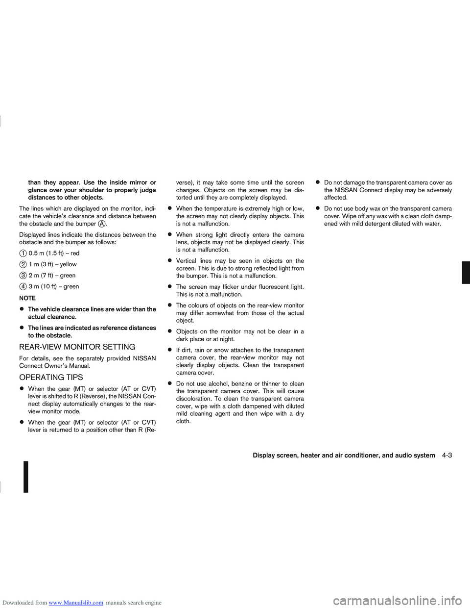
The lines which are displayed on the monitor, indi-
cate the vehicle’s clearance and distance between
the obstacle and the bumper
jA.
Displayed lines indicate the distances between the
obstacle and the bumper as follows:
j1 0.5m(1.5ft)–red
j2 1m(3ft)–yellow
j3 2m(7ft)–green
j4 3m(10ft)–green
NOTE
The vehicle clearance lines are wider than the
actual clearance.
The lines are indicated as reference distances
to the obstacle.
REAR-VIEW MONITOR SETTING
For details, see the separately provided NISSAN
Connect Owner’s Manual.
OPERATING TIPS
When the gear (MT) or selector (AT or CVT)
lever is shifted to R (Reverse), the NISSAN Con-
nect display automatically changes to the rear-
view monitor mode.
When the gear (MT) or selector (AT or CVT)
lever is returned to a position other than R (Re- verse), it may take some time until the screen
changes. Objects on the screen may be dis-
torted until they are completely displayed.
When the temperature is extremely high or low,
the screen may not clearly display objects. This
is not a malfunction.
When strong light directly enters the camera
lens, objects may not be displayed clearly. This
is not a malfunction.
Vertical lines may be seen in objects on the
screen. This is due to strong reflected light from
the bumper. This is not a malfunction.
The screen may flicker under fluorescent light.
This is not a malfunction.
The colours of objects on the rear-view monitor
may differ somewhat from those of the actual
object.
Objects on the monitor may not be clear in a
dark place or at night.
If dirt, rain or snow attaches to the transparent
camera cover, the rear-view monitor may not
clearly display objects. Clean the transparent
camera cover.
Do not use alcohol, benzine or thinner to clean
the transparent camera cover. This will cause
discoloration. To clean the transparent camera
cover, wipe with a cloth dampened with diluted
mild cleaning agent and then wipe with a dry
cloth.
Do not damage the transparent camera cover as
the NISSAN Connect display may be adversely
affected.
Do not use body wax on the transparent camera
cover. Wipe off any wax with a clean cloth damp-
ened with mild detergent diluted with water.
Display screen, heater and air conditioner, and audio system4-3