automatic NISSAN QASHQAI 2013 Owners Manual
[x] Cancel search | Manufacturer: NISSAN, Model Year: 2013, Model line: QASHQAI, Model: NISSAN QASHQAI 2013Pages: 297, PDF Size: 4.09 MB
Page 29 of 297
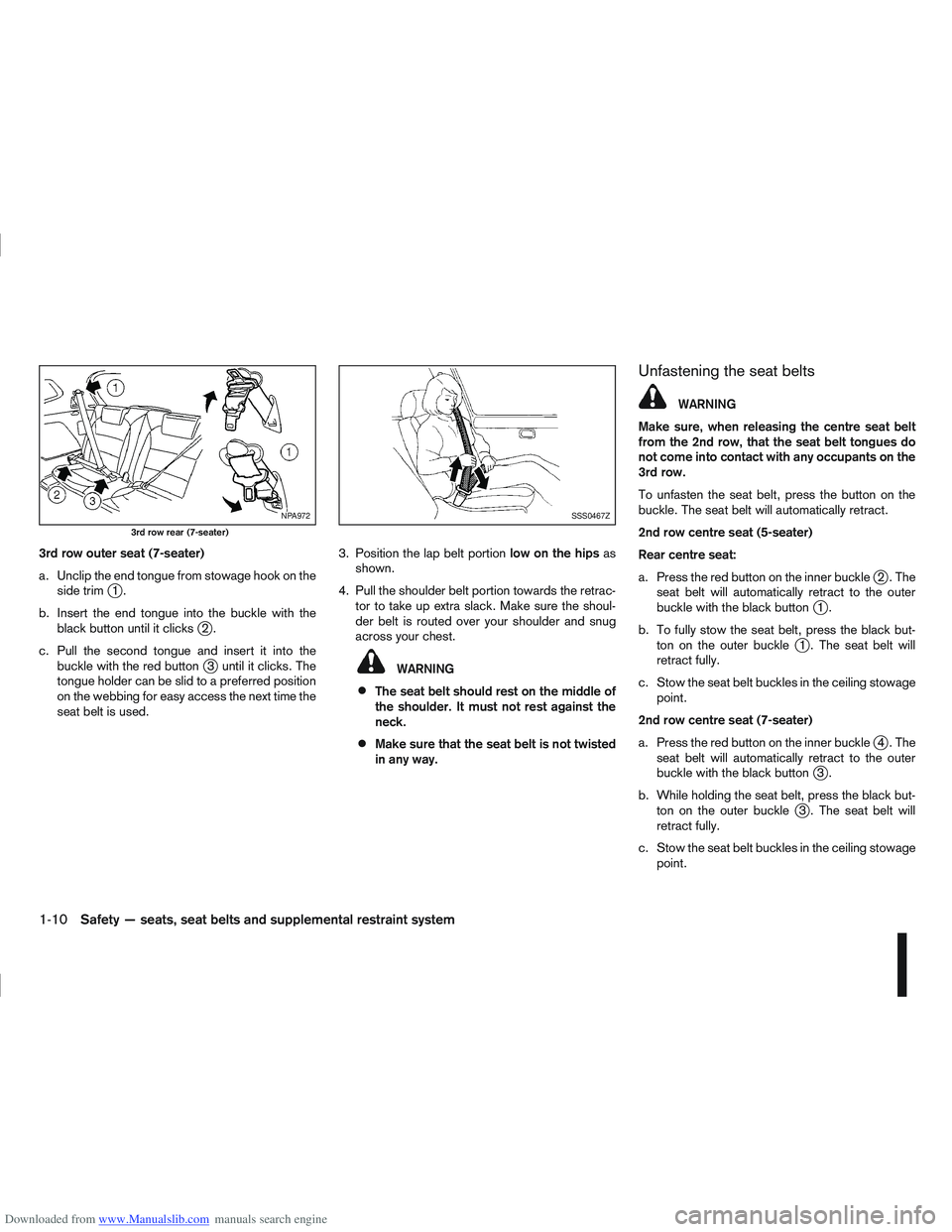
Downloaded from www.Manualslib.com manuals search engine 3rd row outer seat (7-seater)
a. Unclip the end tongue from stowage hook on theside trim
j1.
b. Insert the end tongue into the buckle with the black button until it clicks
j2.
c. Pull the second tongue and insert it into the buckle with the red button
j3 until it clicks. The
tongue holder can be slid to a preferred position
on the webbing for easy access the next time the
seat belt is used. 3. Position the lap belt portion
low on the hipsas
shown.
4. Pull the shoulder belt portion towards the retrac- tor to take up extra slack. Make sure the shoul-
der belt is routed over your shoulder and snug
across your chest.WARNING
The seat belt should rest on the middle of
the shoulder. It must not rest against the
neck.
Make sure that the seat belt is not twisted
in any way.
Unfastening the seat belts
WARNING
Make sure, when releasing the centre seat belt
from the 2nd row, that the seat belt tongues do
not come into contact with any occupants on the
3rd row.
To unfasten the seat belt, press the button on the
buckle. The seat belt will automatically retract.
2nd row centre seat (5-seater)
Rear centre seat:
a. Press the red button on the inner buckle
j2.The
seat belt will automatically retract to the outer
buckle with the black button
j1.
b. To fully stow the seat belt, press the black but- ton on the outer buckle
j1 . The seat belt will
retract fully.
c. Stow the seat belt buckles in the ceiling stowage point.
2nd row centre seat (7-seater)
a. Press the red button on the inner buckle
j4.The
seat belt will automatically retract to the outer
buckle with the black button
j3.
b. While holding the seat belt, press the black but- ton on the outer buckle
j3 . The seat belt will
retract fully.
c. Stow the seat belt buckles in the ceiling stowage point.
NPA972
3rd row rear (7-seater)
SSS0467Z
1-10Safety — seats, seat belts and supplemental restraint system
Page 30 of 297
Downloaded from www.Manualslib.com manuals search engine 3rd row outer seat (7-seater)
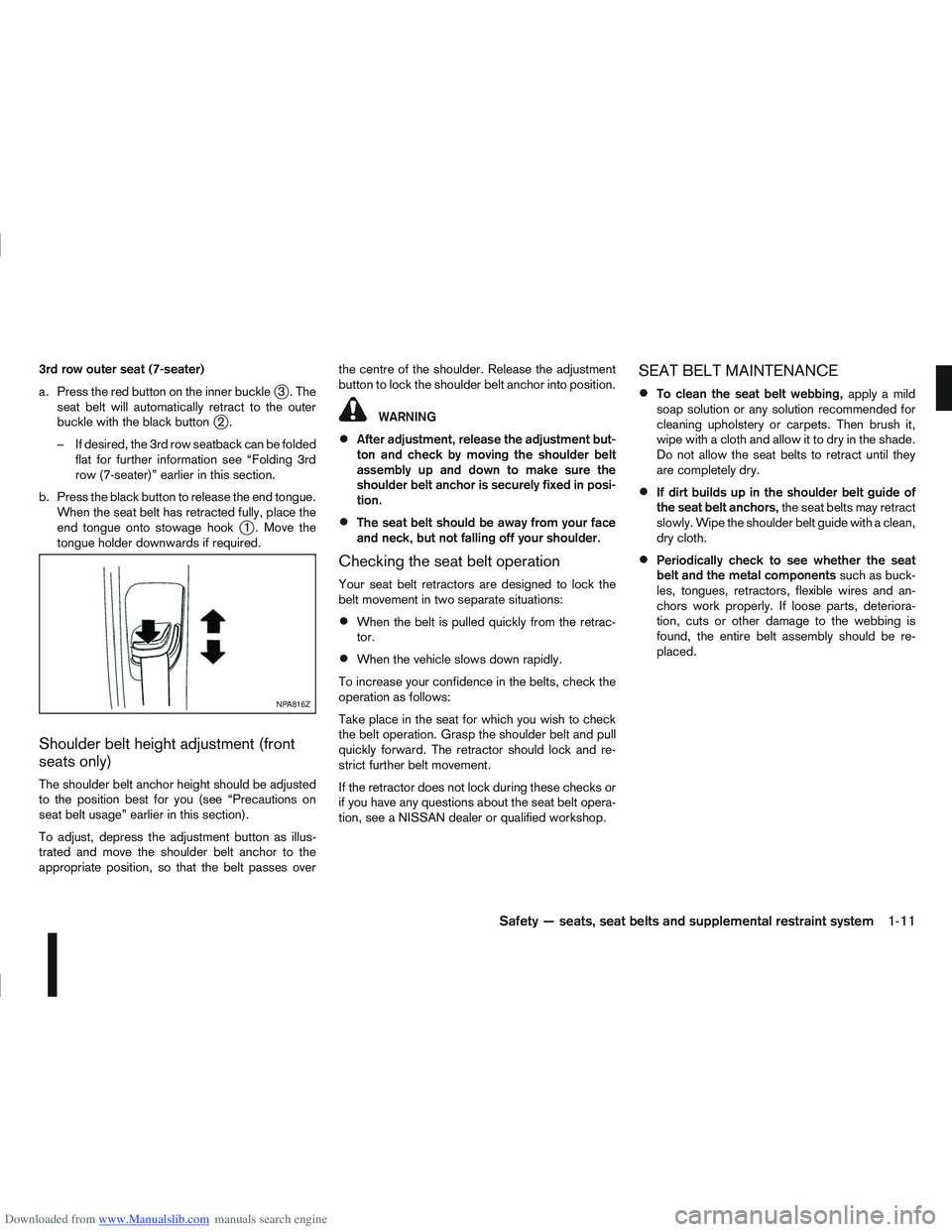
a. Press the red button on the inner buckle
j3.The
seat belt will automatically retract to the outer
buckle with the black button
j2.
– If desired, the 3rd row seatback can be folded flat for further information see “Folding 3rd
row (7-seater)” earlier in this section.
b. Press the black button to release the end tongue. When the seat belt has retracted fully, place the
end tongue onto stowage hook
j1 . Move the
tongue holder downwards if required.
Shoulder belt height adjustment (front
seats only)
The shoulder belt anchor height should be adjusted
to the position best for you (see “Precautions on
seat belt usage” earlier in this section).
To adjust, depress the adjustment button as illus-
trated and move the shoulder belt anchor to the
appropriate position, so that the belt passes over the centre of the shoulder. Release the adjustment
button to lock the shoulder belt anchor into position.
WARNING
After adjustment, release the adjustment but-
ton and check by moving the shoulder belt
assembly up and down to make sure the
shoulder belt anchor is securely fixed in posi-
tion.
The seat belt should be away from your face
and neck, but not falling off your shoulder.
Checking the seat belt operation
Your seat belt retractors are designed to lock the
belt movement in two separate situations:
When the belt is pulled quickly from the retrac-
tor.
When the vehicle slows down rapidly.
To increase your confidence in the belts, check the
operation as follows:
Take place in the seat for which you wish to check
the belt operation. Grasp the shoulder belt and pull
quickly forward. The retractor should lock and re-
strict further belt movement.
If the retractor does not lock during these checks or
if you have any questions about the seat belt opera-
tion, see a NISSAN dealer or qualified workshop.
SEAT BELT MAINTENANCE
To clean the seat belt webbing, apply a mild
soap solution or any solution recommended for
cleaning upholstery or carpets. Then brush it,
wipe with a cloth and allow it to dry in the shade.
Do not allow the seat belts to retract until they
are completely dry.
If dirt builds up in the shoulder belt guide of
the seat belt anchors, the seat belts may retract
slowly. Wipe the shoulder belt guide with a clean,
dry cloth.
Periodically check to see whether the seat
belt and the metal components such as buck-
les, tongues, retractors, flexible wires and an-
chors work properly. If loose parts, deteriora-
tion, cuts or other damage to the webbing is
found, the entire belt assembly should be re-
placed.
NPA816Z
Safety — seats, seat belts and supplemental restraint system1-11
Page 49 of 297
Downloaded from www.Manualslib.com manuals search engine 2Instruments and controls
Instruments and controls
Meters and gauges .................................................. 2-2
Speedometer...................................................... 2-2
Fuel gauge ......................................................... 2-2
Tachometer ........................................................ 2-2
Engine coolant temperature gauge ...................... 2-2
Warning/indicator lights and audible reminders ........ 2-3 Checking bulbs .................................................. 2-3
Warning lights .................................................... 2-3
Indicator lights .................................................... 2-7
Audible reminders............................................... 2-9
Vehicle information display ....................................... 2-11 Warnings and alerts............................................ 2-12
Odometer/twin trip odometer .............................. 2-16
Brightness control .............................................. 2-16
Trip computer ..................................................... 2-16
Settings menu .................................................... 2-18
Cruise control/Speed limiter indicator (where
fitted).................................................................. 2-21
Wiper and washer switch ........................................ 2-21 Windscreen ........................................................ 2-22
Rear window ...................................................... 2-23
Defogger switch ...................................................... 2-23 Rear window defogger ....................................... 2-23
Outside mirror defogger (where fitted) ................ 2-24
Headlight and turn signal switch............................... 2-24 Xenon headlights (where fitted) ........................... 2-24
Headlight switch ................................................. 2-24
Turn signal switch ............................................... 2-26
Fog light switch ....................................................... 2-26 Front fog light (where fitted) ................................ 2-26 Rear fog light ...................................................... 2-27
Headlight aiming control .......................................... 2-27 Headlight aiming control switch (where fitted) ..... 2-27
Automatic aiming control (xenon headlights) ........ 2-27
Headlight cleaner (where fitted) ............................... 2-28
Hazard warning flasher switch ................................. 2-28
Horn ........................................................................\
2-29
Seat heating (where fitted) ....................................... 2-29
Power outlet ............................................................ 2-30
Storage ................................................................... 2-31 Storage trays ...................................................... 2-31
Glove box ........................................................... 2-31
Console box ....................................................... 2-32
Cup holders ....................................................... 2-32
Bottle holder ....................................................... 2-32
Map pocket (where fitted) ................................... 2-32
Seat pocket (where fitted)................................... 2-32
Roof rail (where fitted) ........................................ 2-32
Rear parcel shelf (where fitted) ................................ 2-33
Tonneau cover (where fitted).................................... 2-33
Windows ................................................................. 2-34 Power windows .................................................. 2-34
C-View® glass roof (where fitted) ............................ 2-36 Sunshade operation ............................................ 2-36
System reinitialisation.......................................... 2-37
Interior lights ............................................................ 2-37 Front Room light ................................................. 2-37
Map lights (where fitted) ..................................... 2-38
Rear room/reading light ...................................... 2-38
Luggage compartment light ................................ 2-38
Page 52 of 297
Downloaded from www.Manualslib.com manuals search engine Anti-lock Braking System (ABS) warning
light (orange)Seat belt (driver and front passenger) warn-
ing light (red)Low fuel indicator light (orange)
Brake warning light (red)Supplemental Restraint System (SRS) air
bag warning light (red)Slip indicator light (orange)
Charge warning light (red)Water in fuel filter warning light (orange)Front fog light indicator light (green)
Diesel Particulate Filter (DPF) warning light
(orange)4WD warning light (orange)Rear fog light indicator light (orange)
Electronic Power Assisted Steering (EPAS)
warning light (red)Automatic Transmission check indicator light
(AT models) (orange)High beam indicator light (blue)
Engine oil pressure/level warning light (red)Continuously Variable Transmission (CVT)
indicator light (orange)Dipped beam indicator light (green)
Front passenger air bag deactivated (OFF)
warning light (red)Electronic Stability Programme (ESP) OFF
indicator light (orange)Side light and headlight indicator light
(green)
Malfunction warning light (red)
Malfunction Indicator light (orange)4WD mode indicator light (AUTO) (green)SPORT mode indicator light
Master warning light (orange)4WD mode indicator light (LOCK) (orange)Trailer direction indicator light (green)
NATS security warning light (red)Glow plug indicator light (Diesel engine)
(orange)Turn signal/hazard indicator lights (green)
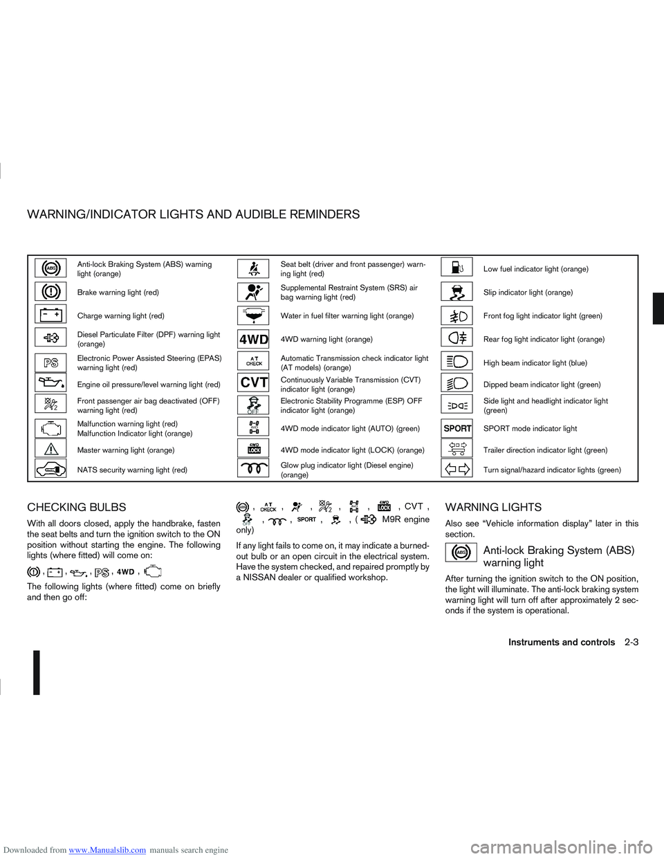
CHECKING BULBS
With all doors closed, apply the handbrake, fasten
the seat belts and turn the ignition switch to the ON
position without starting the engine. The following
lights (where fitted) will come on:
,,,,,
The following lights (where fitted) come on briefly
and then go off:
,,,,,,,
,,,,(M9R engine
only)
If any light fails to come on, it may indicate a burned-
out bulb or an open circuit in the electrical system.
Have the system checked, and repaired promptly by
a NISSAN dealer or qualified workshop.
WARNING LIGHTS
Also see “Vehicle information display” later in this
section.
Anti-lock Braking System (ABS)
warning light
After turning the ignition switch to the ON position,
the light will illuminate. The anti-lock braking system
warning light will turn off after approximately 2 sec-
onds if the system is operational.
WARNING/INDICATOR LIGHTS AND AUDIBLE REMINDERS
Instruments and controls2-3
Page 54 of 297
Downloaded from www.Manualslib.com manuals search engine burns-off the accumulated carbon. This regenera-
tion process is normally automatic and not visible to
the driver.
Regeneration restrictions:
Driving conditions such as frequent short journeys
or stop/start driving can result in excessive build up
of carbon in the filter. When this happens the DPF
warning light will illuminate (and a message will ap-
pear in the vehicle information display, see “Vehicle
information display” later in this section) to inform
you that the vehicle must be driven in a particular
manner to begin regeneration.
When the DPF warning light is illuminated, provided
that legal and safety conditions allow, the vehicle
should be driven at a speed of over 60 km/h (37.5
MPH) until the DPF warning light turns off. This pro-
cess can take up to 30 minutes to complete.
If regeneration fails:
Failure to react to the DPF warning light may lead to
saturation of the DPF system. If this happens the
Malfunction Indicator (MI)
will illuminate indi-
cating that a Service Regeneration by a NISSAN
dealer or qualified workshop is required. The engine
speed may also be limited to 3,000 rpm to protect
the DPF system.
NOTE
Contact a NISSAN dealer or qualified workshop
to perform a forced regeneration.
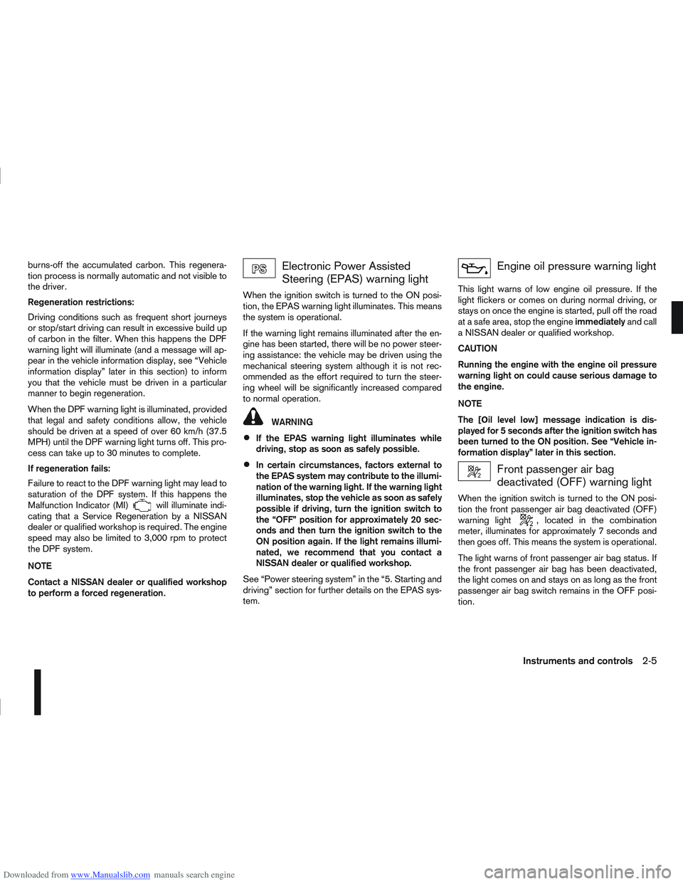
Electronic Power Assisted
Steering (EPAS) warning light
When the ignition switch is turned to the ON posi-
tion, the EPAS warning light illuminates. This means
the system is operational.
If the warning light remains illuminated after the en-
gine has been started, there will be no power steer-
ing assistance: the vehicle may be driven using the
mechanical steering system although it is not rec-
ommended as the effort required to turn the steer-
ing wheel will be significantly increased compared
to normal operation.
WARNING
If the EPAS warning light illuminates while
driving, stop as soon as safely possible.
In certain circumstances, factors external to
the EPAS system may contribute to the illumi-
nation of the warning light. If the warning light
illuminates, stop the vehicle as soon as safely
possible if driving, turn the ignition switch to
the “OFF” position for approximately 20 sec-
onds and then turn the ignition switch to the
ON position again. If the light remains illumi-
nated, we recommend that you contact a
NISSAN dealer or qualified workshop.
See “Power steering system” in the “5. Starting and
driving” section for further details on the EPAS sys-
tem.
Engine oil pressure warning light
This light warns of low engine oil pressure. If the
light flickers or comes on during normal driving, or
stays on once the engine is started, pull off the road
at a safe area, stop the engine immediatelyand call
a NISSAN dealer or qualified workshop.
CAUTION
Running the engine with the engine oil pressure
warning light on could cause serious damage to
the engine.
NOTE
The [Оil lеvеll оw] message indication is dis-
played for 5 seconds after the ignition switch has
been turned to the ON position. See “Vehicle in-
formation display” later in this section.
Front passenger air bag
deactivated (OFF) warning light
When the ignition switch is turned to the ON posi-
tion the front passenger air bag deactivated (OFF)
warning light
, located in the combination
meter, illuminates for approximately 7 seconds and
then goes off. This means the system is operational.
The light warns of front passenger air bag status. If
the front passenger air bag has been deactivated,
the light comes on and stays on as long as the front
passenger air bag switch remains in the OFF posi-
tion.
Instruments and controls2-5
Page 56 of 297
Downloaded from www.Manualslib.com manuals search engine Do not drive on dry, hard surfaced roads in
the LOCK position.
If the 4WD warning light blinks in the follow-
ing sequence while driving, proceed as in-
structed:
– Blinks rapidly (about twice a second)Pull off the road at a safe place and idle
the engine. The driving mode will change
to 2WD to prevent the 4WD system from
malfunctioning. The vehicle can be driven
again as soon as the warning light turns
off.
– Blinks slowly (about once every 2 seconds) Change the driving mode to 2WD and re-
duce the vehicle speed as soon as safely
possible.
If the warning light is still on after performing the
above operation, have the system checked by a
NISSAN dealer or qualified workshop as soon as
possible.
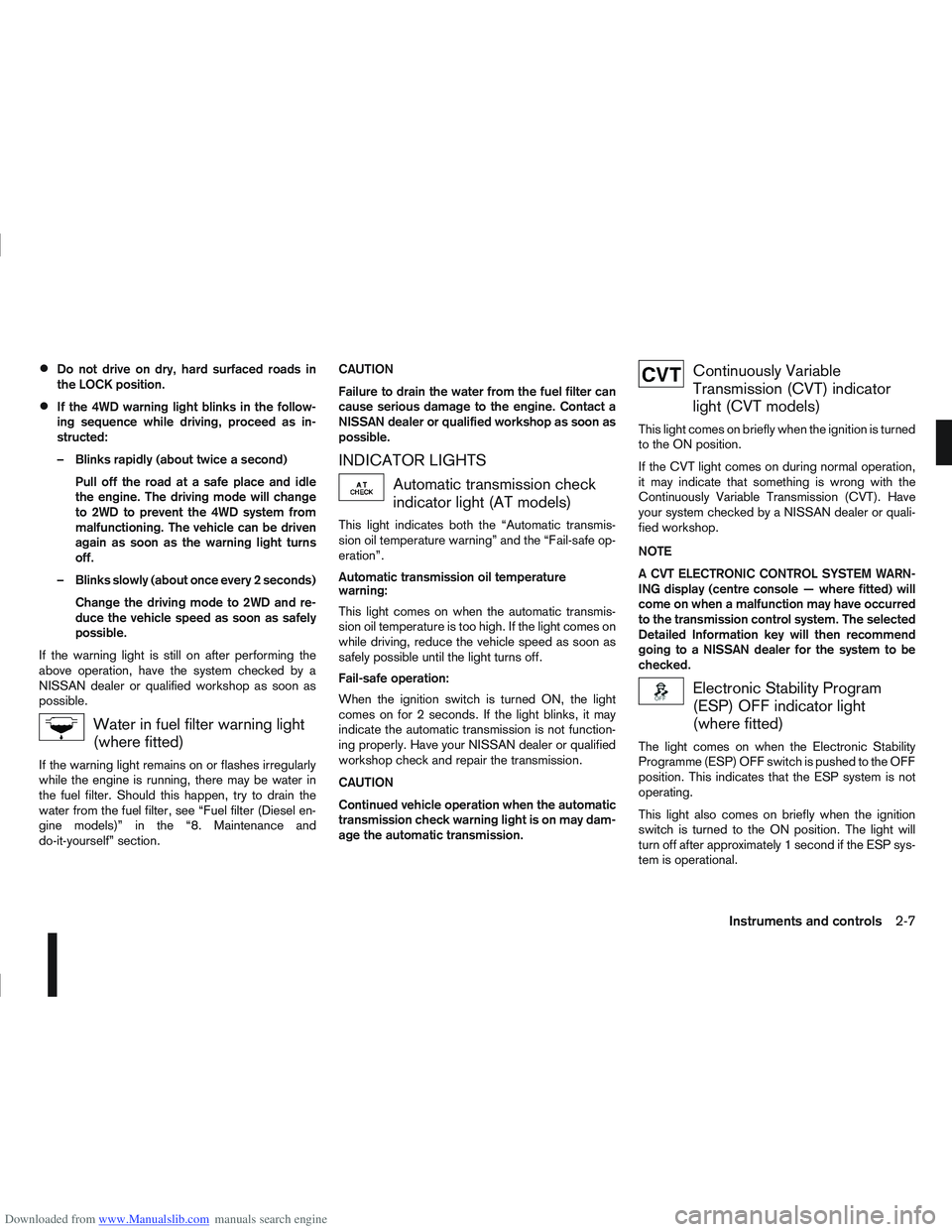
Water in fuel filter warning light
(where fitted)
If the warning light remains on or flashes irregularly
while the engine is running, there may be water in
the fuel filter. Should this happen, try to drain the
water from the fuel filter, see “Fuel filter (Diesel en-
gine models)” in the “8. Maintenance and
do-it-yourself” section. CAUTION
Failure to drain the water from the fuel filter can
cause serious damage to the engine. Contact a
NISSAN dealer or qualified workshop as soon as
possible.
INDICATOR LIGHTS
Automatic transmission check
indicator light (AT models)
This light indicates both the “Automatic transmis-
sion oil temperature warning” and the “Fail-safe op-
eration”.
Automatic transmission oil temperature
warning:
This light comes on when the automatic transmis-
sion oil temperature is too high. If the light comes on
while driving, reduce the vehicle speed as soon as
safely possible until the light turns off.
Fail-safe operation:
When the ignition switch is turned ON, the light
comes on for 2 seconds. If the light blinks, it may
indicate the automatic transmission is not function-
ing properly. Have your NISSAN dealer or qualified
workshop check and repair the transmission.
CAUTION
Continued vehicle operation when the automatic
transmission check warning light is on may dam-
age the automatic transmission.
Continuously Variable
Transmission (CVT) indicator
light (CVT models)
This light comes on briefly when the ignition is turned
to the ON position.
If the CVT light comes on during normal operation,
it may indicate that something is wrong with the
Continuously Variable Transmission (CVT). Have
your system checked by a NISSAN dealer or quali-
fied workshop.
NOTE
A CVT ELECTRONIC CONTROL SYSTEM WARN-
ING display (centre console — where fitted) will
come on when a malfunction may have occurred
to the transmission control system. The selected
Detailed Information key will then recommend
going to a NISSAN dealer for the system to be
checked.
Electronic Stability Program
(ESP) OFF indicator light
(where fitted)
The light comes on when the Electronic Stability
Programme (ESP) OFF switch is pushed to the OFF
position. This indicates that the ESP system is not
operating.
This light also comes on briefly when the ignition
switch is turned to the ON position. The light will
turn off after approximately 1 second if the ESP sys-
tem is operational.
Instruments and controls2-7
Page 64 of 297
![NISSAN QASHQAI 2013 Owners Manual Downloaded from www.Manualslib.com manuals search engine However reset is possible (only after the oil was
changed) using the [Service] menu item in the
[Settings] menu. See “[Maintenance]” later](/img/5/56763/w960_56763-63.png "NISSAN QASHQAI 2013 Owners Manual Downloaded from www.Manualslib.com manuals search engine However reset is possible (only after the oil was
changed) using the [Service] menu item in the
[Settings] menu. See “[Maintenance]” later")
Downloaded from www.Manualslib.com manuals search engine However reset is possible (only after the oil was
changed) using the [Service] menu item in the
[Settings] menu. See “[Maintenance]” later in this
section
Have the vehicle inspected by a NISSAN dealer
or qualified workshop if these conditions occur.
j20Distance to maintenance alert
(where fitted)
This alert reminds when maintenance is due in the
shown distance. The alert is shown for 10 seconds
at ignition ON, when the distance to the next main-
tenance interval is below 5000 km (3100 Miles).
The message is shown until the steering wheel
switch
ji (where fitted) is pressed.
NOTE
Visit a NISSAN dealer or qualified workshop
before the maintenance due alertj19reaches
0 km (miles) to perform maintenance (oil
change).
The maintenance interval will reduce faster
with certain types of driving, especially at low
speeds in urban conditions.
j21Tyre change alert
You can set a distance for changing tyres. See
“[Maintenance]” later in this section
j22Maintenance alert
You can set a distance for a non specific mainte-
nance item. See “[Maintenance]” later in this sec-
tion
j23Low temperature warning
If, during driving, the temperature falls below 4ºC
this alert will appear to indicate low outside air tem-
perature. You can switch the low temperature warn-
ing [On] or [Off]. See “[Units]” later in this section
CAUTION
Even if the alert is not on, there is no guarantee
that the road is free of hazards caused by in-
clement weather.
NOTE
The outside air temperature sensor is located at
the front of the vehicle. At low speeds the sensor
can be affected by engine heat, heat reflected
from the road surface and exhaust from other
vehicles, these influences can cause the display
to be inaccurate. To compensate, the outside air
temperature display is designed to react slowly
to increasing temperatures, but quickly to falling
temperatures.
j24Low fuel warning
This warning appears when the fuel level in the tank
is getting low. Refuel as soon as it is convenient,
preferably before the fuel gauge reaches the empty
position. For more information, see “Fuel gauge”
earlier in this section.
j25Driver alert
This warning appears when the previously set time
for a break is reached. You can set the time for up
to 6 hours in the setting menu. (See “Settings menu”
later in this section.)
Stop/Start System (where fitted)
For more information, see “Stop/Start System
(where fitted)” in the “5. Starting and driving” sec-
tion
j26Engine stop:
If the engine stops when the Stop/Start System is
activated, the message is shown.
j27Auto start deactivation:
If the engine stops when the Stop/Start System is
activated, and will not start automatically, the mes-
sage is shown.
j28System fault:
If the Stop/Start System is activated, but does not
operate correctly, the message is shown. Visit a
NISSAN dealer or qualified workshop.
Activating or deactivating using the Stop/Start
System OFF switch:
Using the Stop/Start System OFF switch activates
or deactivates the Stop/Start System. This is shown
in the vehicle information display:
j29 :The Stop/Start System OFF switch is
pushed to the “ON” position.
j30 :The Stop/Start System OFF switch is pushed to
the “OFF” position.
Instruments and controls2-15
Page 66 of 297
![NISSAN QASHQAI 2013 Owners Manual Downloaded from www.Manualslib.com manuals search engine j2 Average speed
The [Average speed] mode shows the average ve-
hicle speed since the last reset.
j3 Driving distance
The [Driving distance] mo](/img/5/56763/w960_56763-65.png "NISSAN QASHQAI 2013 Owners Manual Downloaded from www.Manualslib.com manuals search engine j2 Average speed
The [Average speed] mode shows the average ve-
hicle speed since the last reset.
j3 Driving distance
The [Driving distance] mo")
Downloaded from www.Manualslib.com manuals search engine j2 Average speed
The [Average speed] mode shows the average ve-
hicle speed since the last reset.
j3 Driving distance
The [Driving distance] mode shows the distance
driven since the last reset.
j4 Elapsed time
The [Elapsed Time] mode shows the time since the
last reset.
j5 Range (km or MILES)
The [Range] mode provides you with an estimation
of the distance that can be driven before refuelling
(distance to empty). The range is constantly being
calculated, based on the amount of fuel in the fuel
tank and the actual fuel consumption.
When the fuel level gets close to empty, the range
will change to “----”.
If the amount of fuel added is small, the display
just before the ignition switch is turned to the
“OFF” position may continue to be displayed.
When driving uphill or corners, the fuel in the
tank shifts, this may momentarily change the dis-
play.
j6 Settings
The [Settings] item is only displayed when using theswitch to control the trip computer.
Rotate the
switch to enter the [Settings] menu For more information, see “Settings menu” later in
this section.
j7 CO2 saved (where fitted)
Estimated quantity of CO2 exhaust emissions pre-
vented by Stop/Start System shown every time the
engine is automatically stopped.
For more information, see “Stop/Start System
(where fitted)” in the “5. Starting and driving” sec-
tion
Instruments and controls2-17
Page 71 of 297
Downloaded from www.Manualslib.com manuals search engine WINDSCREEN
The windscreen wiper and washer can be operated
when the ignition switch is in the ON position.
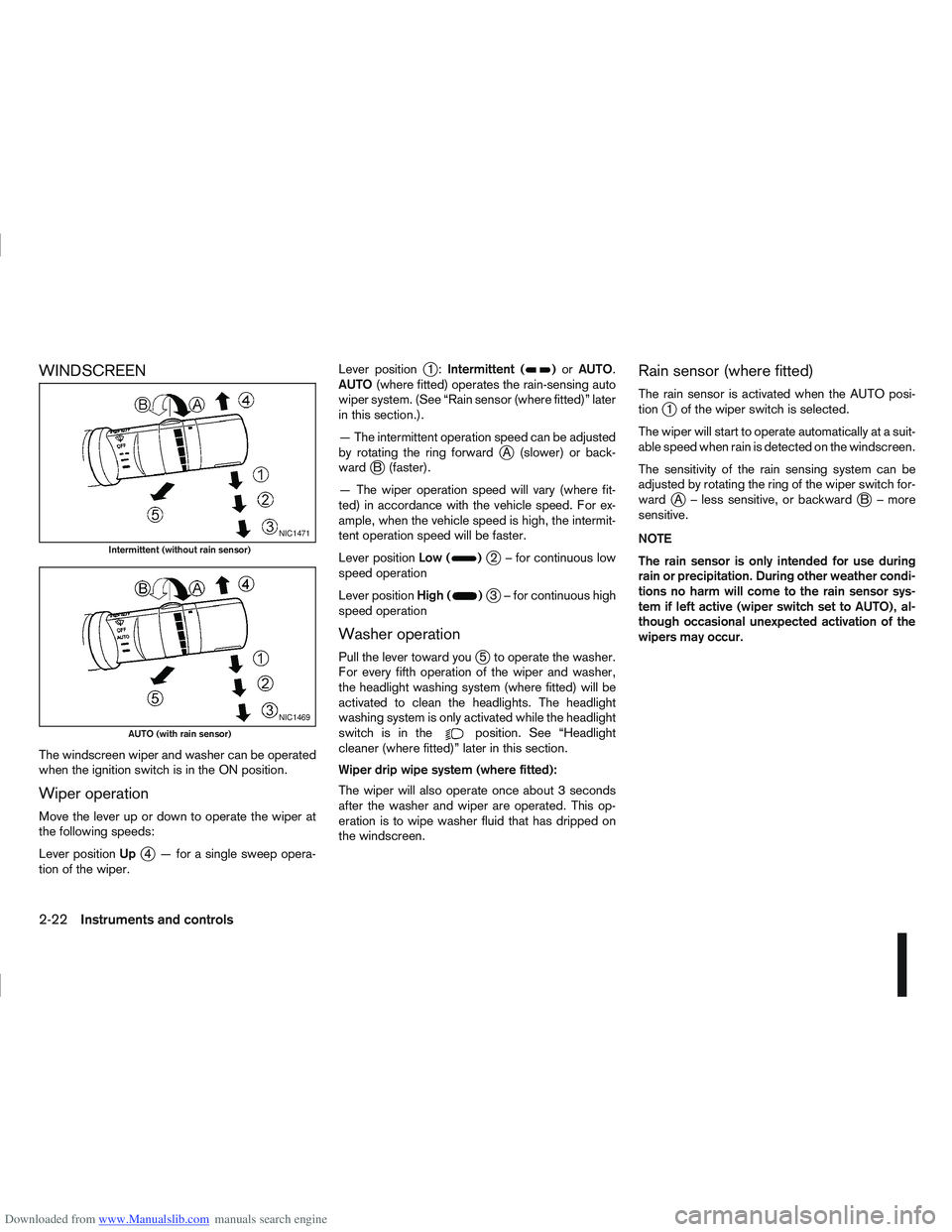
Wiper operation
Move the lever up or down to operate the wiper at
the following speeds:
Lever positionUp
j4 — for a single sweep opera-
tion of the wiper. Lever position
j1:
Intermittent ()or AUTO.
AUTO (where fitted) operates the rain-sensing auto
wiper system. (See “Rain sensor (where fitted)” later
in this section.).
— The intermittent operation speed can be adjusted
by rotating the ring forward
jA (slower) or back-
wardjB (faster).
— The wiper operation speed will vary (where fit-
ted) in accordance with the vehicle speed. For ex-
ample, when the vehicle speed is high, the intermit-
tent operation speed will be faster.
Lever position Low (
)j2 – for continuous low
speed operation
Lever position High (
)j3 – for continuous high
speed operation
Washer operation
Pull the lever toward youj5 to operate the washer.
For every fifth operation of the wiper and washer,
the headlight washing system (where fitted) will be
activated to clean the headlights. The headlight
washing system is only activated while the headlight
switchisinthe
position. See “Headlight
cleaner (where fitted)” later in this section.
Wiper drip wipe system (where fitted):
The wiper will also operate once about 3 seconds
after the washer and wiper are operated. This op-
eration is to wipe washer fluid that has dripped on
the windscreen.
Rain sensor (where fitted)
The rain sensor is activated when the AUTO posi-
tionj1 of the wiper switch is selected.
The wiper will start to operate automatically at a suit-
able speed when rain is detected on the windscreen.
The sensitivity of the rain sensing system can be
adjusted by rotating the ring of the wiper switch for-
ward
jA – less sensitive, or backwardjB – more
sensitive.
NOTE
The rain sensor is only intended for use during
rain or precipitation. During other weather condi-
tions no harm will come to the rain sensor sys-
tem if left active (wiper switch set to AUTO), al-
though occasional unexpected activation of the
wipers may occur.
NIC1471
Intermittent (without rain sensor)
NIC1469
AUTO (with rain sensor)
2-22Instruments and controls
Page 72 of 297
Downloaded from www.Manualslib.com manuals search engine REAR WINDOW
WARNING
In freezing temperatures the washer solution
may freeze on the rear window and obscure your
vision. Warm the rear window with the rear win-
dow defogger before you wash the rear window.
CAUTION
Do not operate the washer continuously for
more than 15 seconds.
Do not operate the washer if the reservoir
tank is empty or frozen.
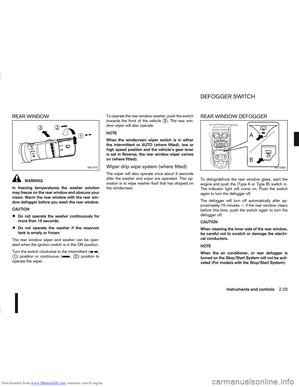
The rear window wiper and washer can be oper-
ated when the ignition switch is in the ON position.
Turn the switch clockwise to the intermittent (
,j1 ) position or continuous (,j2 ) position to
operate the wiper. To operate the rear window washer, push the switch
towards the front of the vehicle
j3 . The rear win-
dow wiper will also operate.
NOTE
When the windscreen wiper switch is in either
the intermittent or AUTO (where fitted), low or
high speed position and the vehicle’s gear lever
is set in Reverse, the rear window wiper comes
on (where fitted).
Wiper drip wipe system (where fitted)
The wiper will also operate once about 3 seconds
after the washer and wiper are operated. This op-
eration is to wipe washer fluid that has dripped on
the windscreen.
REAR WINDOW DEFOGGER
To defog/defrost the rear window glass, start the
engine and push the (Type A or Type B) switch in.
The indicator light will come on. Push the switch
again to turn the defogger off.
The defogger will turn off automatically after ap-
proximately 15 minutes — if the rear window clears
before this time, push the switch again to turn the
defogger off.
CAUTION
When cleaning the inner side of the rear window,
be careful not to scratch or damage the electri-
cal conductors.
NOTE
When the air conditioner, or rear defogger is
turned on the Stop/Start System will not be acti-
vated (For models with the Stop/Start System).
NIC1472NIC1326Z
DEFOGGER SWITCH
Instruments and controls2-23