bonnet NISSAN QASHQAI 2015 Owner´s Manual
[x] Cancel search | Manufacturer: NISSAN, Model Year: 2015, Model line: QASHQAI, Model: NISSAN QASHQAI 2015Pages: 338, PDF Size: 4.88 MB
Page 9 of 338
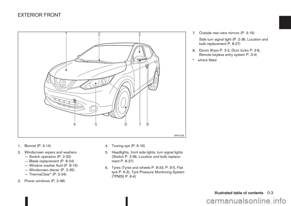
1.Bonnet (P. 3-14)
2.Windscreen wipers and washers
— Switch operation (P. 2-32)
— Blade replacement (P. 8-24)
— Window washer fluid (P. 8-15)
— Windscreen deicer (P. 2-35)
— ThermaClear* (P. 2-34)
3.Power windows (P. 2-48)4.Towing eye (P. 6-16)
5.Headlights, front side lights, turn signal lights
(Switch P. 2-36, Location and bulb replace-
ment P. 8-27)
6.Tyres (Tyres and wheels P. 8-33, P. 9-5, Flat
tyre P. 6-3), Tyre Pressure Monitoring System
(TPMS) P. 6-4)7.Outside rear-view mirrors (P. 3-19)
Side turn signal light (P. 2-36, Location and
bulb replacement P. 8-27)
8.Doors (Keys P. 3-2, Door locks P. 3-8,
Remote keyless entry system P. 3-4)
* where fitted
NPA1245
EXTERIOR FRONT
Illustrated table of contents0-3
Page 12 of 338
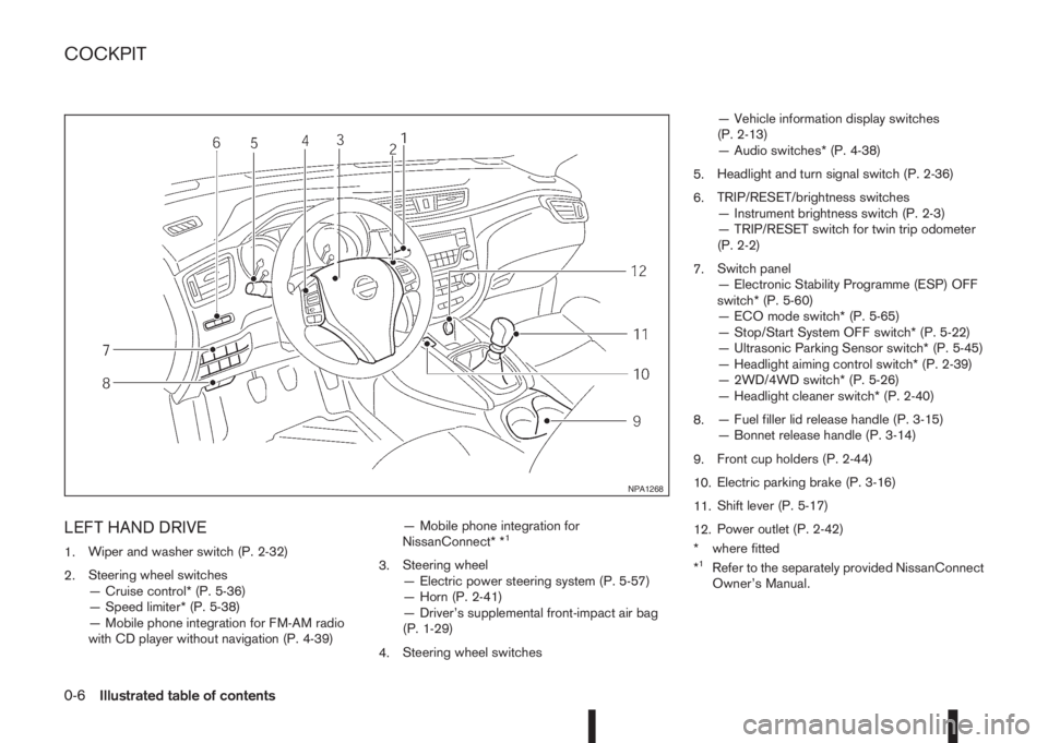
LEFT HAND DRIVE
1.Wiper and washer switch (P. 2-32)
2.Steering wheel switches
— Cruise control* (P. 5-36)
— Speed limiter* (P. 5-38)
— Mobile phone integration for FM-AM radio
with CD player without navigation (P. 4-39)— Mobile phone integration for
NissanConnect* *1
3.Steering wheel
— Electric power steering system (P. 5-57)
— Horn (P. 2-41)
— Driver’s supplemental front-impact air bag
(P. 1-29)
4.Steering wheel switches— Vehicle information display switches
(P. 2-13)
— Audio switches* (P. 4-38)
5.Headlight and turn signal switch (P. 2-36)
6.TRIP/RESET/brightness switches
— Instrument brightness switch (P. 2-3)
— TRIP/RESET switch for twin trip odometer
(P. 2-2)
7.Switch panel
— Electronic Stability Programme (ESP) OFF
switch* (P. 5-60)
— ECO mode switch* (P. 5-65)
— Stop/Start System OFF switch* (P. 5-22)
— Ultrasonic Parking Sensor switch* (P. 5-45)
— Headlight aiming control switch* (P. 2-39)
— 2WD/4WD switch* (P. 5-26)
— Headlight cleaner switch* (P. 2-40)
8.— Fuel filler lid release handle (P. 3-15)
— Bonnet release handle (P. 3-14)
9.Front cup holders (P. 2-44)
10.Electric parking brake (P. 3-16)
11.Shift lever (P. 5-17)
12.Power outlet (P. 2-42)
* where fitted
*1Refer to the separately provided NissanConnect
Owner’s Manual.
NPA1268
COCKPIT
0-6Illustrated table of contents
Page 13 of 338
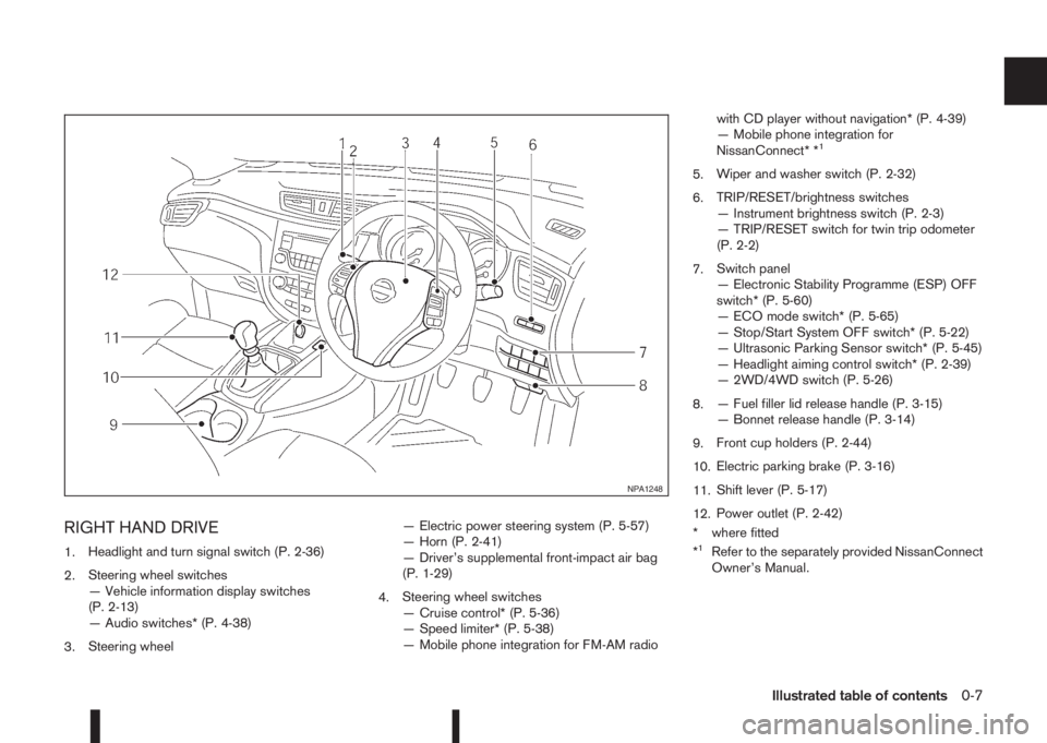
RIGHT HAND DRIVE
1.Headlight and turn signal switch (P. 2-36)
2.Steering wheel switches
— Vehicle information display switches
(P. 2-13)
— Audio switches* (P. 4-38)
3.Steering wheel— Electric power steering system (P. 5-57)
— Horn (P. 2-41)
— Driver’s supplemental front-impact air bag
(P. 1-29)
4.Steering wheel switches
— Cruise control* (P. 5-36)
— Speed limiter* (P. 5-38)
— Mobile phone integration for FM-AM radiowith CD player without navigation* (P. 4-39)
— Mobile phone integration for
NissanConnect* *
1
5.Wiper and washer switch (P. 2-32)
6.TRIP/RESET/brightness switches
— Instrument brightness switch (P. 2-3)
— TRIP/RESET switch for twin trip odometer
(P. 2-2)
7.Switch panel
— Electronic Stability Programme (ESP) OFF
switch* (P. 5-60)
— ECO mode switch* (P. 5-65)
— Stop/Start System OFF switch* (P. 5-22)
— Ultrasonic Parking Sensor switch* (P. 5-45)
— Headlight aiming control switch* (P. 2-39)
— 2WD/4WD switch (P. 5-26)
8.— Fuel filler lid release handle (P. 3-15)
— Bonnet release handle (P. 3-14)
9.Front cup holders (P. 2-44)
10.Electric parking brake (P. 3-16)
11.Shift lever (P. 5-17)
12.Power outlet (P. 2-42)
* where fitted
*
1Refer to the separately provided NissanConnect
Owner’s Manual.
NPA1248
Illustrated table of contents0-7
Page 57 of 338
•No unauthorised changes should be made to
any components or wiring of the air bag sys-
tem. This is to prevent accidental inflation of
the air bag or damage to the air bag system.
•Tampering with the air bag system may result
in serious personal injury. Tampering includes
making changes to the steering wheel and
the instrument panel assembly by placing ma-
terial over the steering pad and above the
dashboard, or by installing additional trim ma-
terial around the air bag system.
•Do not attach any objects to the steering
wheel pad or to the instrument panel. Objects
attached to the steering wheel pad and in-
strument panel may become dangerous pro-
jectiles and cause injury if the air bag inflates.
•Work on and around the air bag system should
be done by a NISSAN dealer or qualified work-
shop. Installation of electrical equipment
should be done by a NISSAN dealer or quali-
fied workshop. The yellow SRS wiring har-
nesses* should not be modified or discon-
nected. Unauthorised electrical test equip-
ment and probing devices should not be used
on the air bag system.
* SRS wiring harnesses are covered with yellow
insulation either just before the harness con-
nectors or on the complete harness, for easy
identification.
REPAIR AND REPLACEMENT
PROCEDURE
WARNING
•Once the air bags have been inflated, the air
bag modules will not function and must be
replaced. The air bag modules must be re-
placed by a NISSAN dealer or qualified work-
shop. The inflated air bag modules cannot be
repaired.
•The air bag systems should be inspected by a
NISSAN dealer or qualified workshop if there
is any damage to the front end portion of the
vehicle.
•When selling your vehicle, we request that you
inform the buyer about the air bag system and
guide the buyer to the appropriate sections in
this Owner’s Manual.
•If you need to dispose of the SRS or scrap the
vehicle, contact a NISSAN dealer or qualified
workshop. Correct disposal procedures are
set forth in the appropriate NISSAN Service
Manual. Incorrect disposal procedures could
cause personal injury.
The air bags and pre-tensioner seat belts are de-
signed to activate on a one-time-only basis. As a
reminder, unless the SRS air bag warning light is
damaged, the SRS air bag warning light remains
illuminated after inflation has occurred. The repair
and replacement of the SRS should be done only by
a NISSAN dealer or qualified workshop.When maintenance work is required on the vehicle,
information about the air bags, pre-tensioner seat
belts and related parts should be pointed out to the
person performing the maintenance. The ignition
switch should always be in the LOCK position when
working under the bonnet or inside the vehicle.
Safety — seats, seat belts and supplemental restraint system1-37
Page 71 of 338
Seat belt reminder chime
A chime will sound for approximately 90 seconds if
the vehicle’s speed exceeds 15 km/h (9 MPH) and
the driver’s seat belt or front passenger’s seat belt,
if occupied (where fitted) is not securely fastened.
See “Seat belt warnings” in the “1. Safety — Seats,
Seat belts and Supplemental Restraint System” sec-
tion.
Key reminder buzzer (Intelligent Key
models)
The external buzzer will beep 3 times if:
•The Intelligent Key is removed from the vehicle
while the ignition is not in the LOCK position.
•The vehicle is being locked remotely or using an
outside door lock switch and the Intelligent Key
has been left inside the vehicle.
Park reminder chime (where fitted)
A chime will sound if the ignition switch is placed in
the LOCK position and the shift lever is not in the P
(Park) position.
Stop/Start System reminder buzzer
(where fitted)
The engine will shift to the normal stopped state if
any of the following operations is made during Stop/
Start System activation, and the Stop/Start System
buzzer will sound if:
– The driver’s seat belt is unfastened and the driv-
er’s door is open (MT models)– The vehicle engine bonnet is open.
When any of the above conditions continues for
over 3 minutes the Stop/Start System buzzer will
sound in 5-minute intervals as a reminder to prevent
the possibility of a dead battery. Use the ignition
switch to turn off the engine.
Close the bonnet or the driver’s door, or fasten the
seat belt then restart the engine using the ignition
switch.
For more information, see “[Stop/Start]” in the “5. In-
struments and controls” section and “Stop/Start
System (where fitted)” in the “5. Starting and driving”
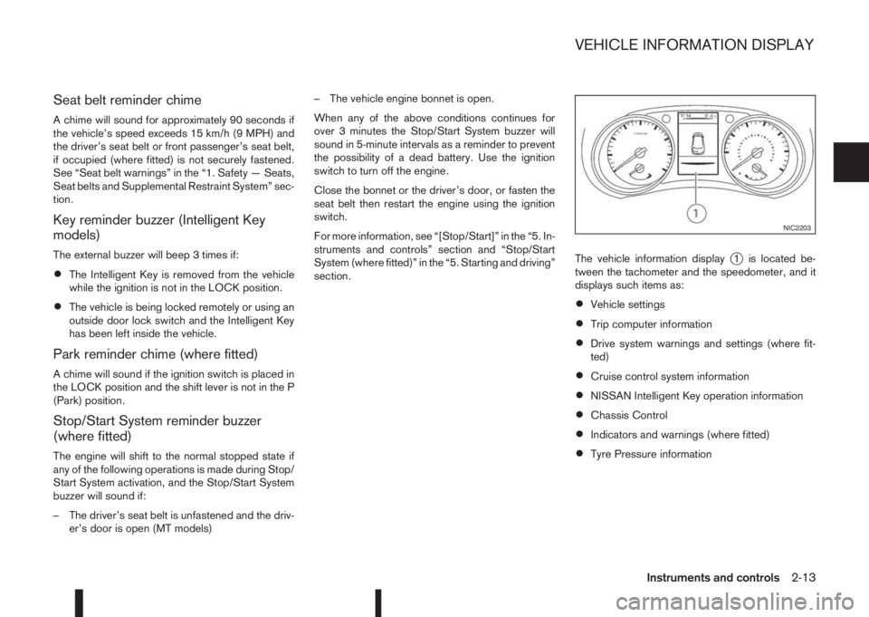
section.The vehicle information display
j1 is located be-
tween the tachometer and the speedometer, and it
displays such items as:
•Vehicle settings
•Trip computer information
•Drive system warnings and settings (where fit-
ted)
•Cruise control system information
•NISSAN Intelligent Key operation information
•Chassis Control
•Indicators and warnings (where fitted)
•Tyre Pressure information
NIC2203
VEHICLE INFORMATION DISPLAY
Instruments and controls2-13
Page 90 of 338
WARNING
In freezing temperatures the washer fluid may
freeze on the windscreen and obscure your vi-
sion. Warm the windscreen with the defogger be-
fore you wash it.
CAUTION
•Do not open/release the bonnet when the
front wiper arms are raised from their original
position.
•Do not operate the washer continuously for
more than 15 seconds.
•Do not operate the washer if the reservoir
tank is empty or frozen.
WINDSCREEN
The windscreen wiper and washer can be operated
when the ignition switch is in the ON position.
Wiper operation
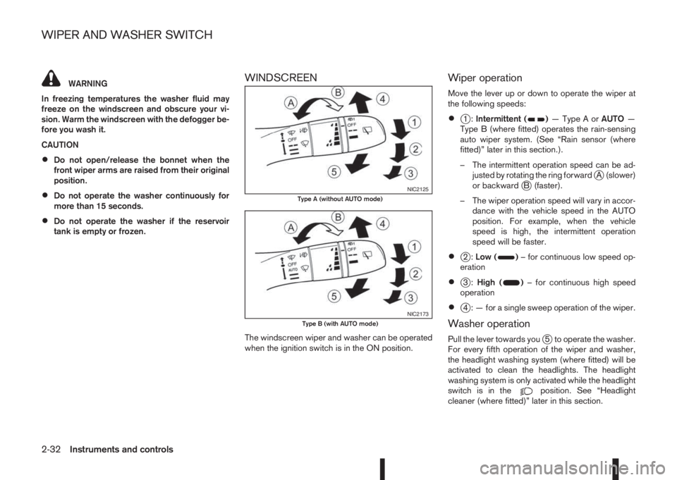
Move the lever up or down to operate the wiper at
the following speeds:
•j1:Intermittent ()—TypeAorAUTO—
Type B (where fitted) operates the rain-sensing
auto wiper system. (See “Rain sensor (where
fitted)” later in this section.).
– The intermittent operation speed can be ad-
justed by rotating the ring forward
jA (slower)
or backwardjB (faster).
– The wiper operation speed will vary in accor-
dance with the vehicle speed in the AUTO
position. For example, when the vehicle
speed is high, the intermittent operation
speed will be faster.
•j2:Low ()– for continuous low speed op-
eration
•j3:High ()– for continuous high speed
operation
•j4 : — for a single sweep operation of the wiper.
Washer operation
Pull the lever towards youj5 to operate the washer.
For every fifth operation of the wiper and washer,
the headlight washing system (where fitted) will be
activated to clean the headlights. The headlight
washing system is only activated while the headlight
switch is in the
position. See “Headlight
cleaner (where fitted)” later in this section.
NIC2125Type A (without AUTO mode)
NIC2173Type B (with AUTO mode)
WIPER AND WASHER SWITCH
2-32Instruments and controls
Page 111 of 338
3Pre-driving checks and adjustmentsPre-driving checks and adjustments
Keys ........................................................................ 3-2
NISSAN Anti-Theft System (NATS)* key ............. 3-2
Intelligent Key (where fitted)................................ 3-2
Key number ........................................................ 3-3
New keys ........................................................... 3-3
Emergency/mechanical key (Intelligent Key
models) .............................................................. 3-3
Integrated keyfob/remote control system .................. 3-4
Switching from Convenience mode to
Anti-hijack mode (where fitted) ............................ 3-5
Using the remote keyless entry system ................ 3-5
Locking the doors ............................................... 3-5
Unlocking the doors ............................................ 3-5
Keyfob operation failure ...................................... 3-5
Intelligent Key system (where fitted) ......................... 3-6
Intelligent Key operating range ............................ 3-6
Using Intelligent Key system................................ 3-6
Locking/unlocking .............................................. 3-7
Starting the engine with the Intelligent Key .......... 3-8
Door locks ............................................................... 3-8
Super Lock system (RHD models) ...................... 3-8
Locking/unlocking with the key (vehicle dead
battery) ............................................................... 3-9Inside door handle .............................................. 3-10
Power door lock switch ...................................... 3-10
Child safety lock — rear doors............................ 3-11
Back door lock ................................................... 3-11
Security system ....................................................... 3-12
Alarm system (where fitted) ................................ 3-12
NISSAN Anti-Theft System (NATS)..................... 3-13
Bonnet release ........................................................ 3-14
Fuel filler lid ............................................................. 3-15
Fuel filler lid opener lever .................................... 3-15
Fuel filler cap ...................................................... 3-15
Parking brake switch ............................................... 3-16
Driving away when towing a trailer ...................... 3-17
Steering wheel......................................................... 3-18
Sun visors ............................................................... 3-18
Mirrors..................................................................... 3-18
Inside rear-view mirror ........................................ 3-18
Automatic anti-dazzling inside mirror (where
fitted).................................................................. 3-19
Outside rear-view mirrors.................................... 3-19
Vanity mirror ....................................................... 3-20
Page 122 of 338
Vehicle dead battery – Back door lock
release lever (where fitted)
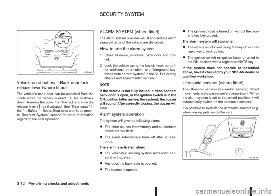
The vehicle’s back door can be unlocked from the
inside when the battery is dead. Tilt the seatback
down. Remove the cover from the lock and slide the
release lever
j1 as illustrated. See “Rear seats” in
the “1. Safety — Seats, Seat belts and Supplemen-
tal Restraint System” section for more information
regarding the seat operation.
ALARM SYSTEM (where fitted)
The alarm system provides visual and audible alarm
signals if parts of the vehicle are disturbed.
How to arm the alarm system
1. Close all doors, windows, back door and bon-
net.
2. Lock the vehicle using the keyfob (lock button),
for additional information, see “Integrated key-
fob/remote control system” in the “3. Pre-driving
checks and adjustments” section.
NOTE
If the vehicle is not fully locked, a door/bonnet/
back door is open, or the ignition switch is in the
ON position (after arming the system), the buzzer
will sound. After correctly closing, the buzzer will
stop.
Alarm system operation
The system will give the following alarm:
•The siren sounds intermittently and all direction
indicators will flash.
•The alarm automatically turns off after 28 sec-
onds.
The alarm is activated when:
•The volumetric sensing system (ultrasonic sen-
sors) is triggered.
•Any door/the back door is opened.
•The bonnet is opened.
•The ignition circuit is turned on without the own-
er’s key being used.
The alarm system will stop when:
•The vehicle is unlocked using the keyfob or intel-
ligent key unlock button.
•The ignition switch or ignition knob is turned to
the ON position with a registered NATS key.
If the system does not operate as described
above, have it checked by your NISSAN dealer or
qualified workshop.
Ultrasonic sensors (where fitted)
The ultrasonic sensors (volumetric sensing) detect
movements in the passenger’s compartment. When
the alarm system is set to the armed position, it will
automatically switch on the ultrasonic sensors.
It is possible to exclude the ultrasonic sensors (e.g.
when leaving pets inside the car).
NPA990
NIC2219
SECURITY SYSTEM
3-12Pre-driving checks and adjustments
Page 123 of 338
To exclude the ultrasonic sensors:
1. Press the ultrasonic sensor deactivation button
j1.
2. Close the door(s)/bonnet/back door and press
the lock button
on the keyfob to lock all doors/
back door.
The ultrasonic sensors are now excluded from the
alarm system. All other functions of the system re-
main activated until the alarm system is disarmed
again.
NOTE
One or any further number of presses of the ul-
trasonic sensor deactivation button
j1 excludes
the ultrasonic sensors for the next time the alarm
system is armed and only that instance. Pressing
the button twice does not reactivate the system.
NISSAN ANTI-THEFT SYSTEM (NATS)
The NISSAN Anti-Theft System (NATS)* will not
allow the engine to start without the use of the reg-
istered NATS key.
* Immobilizer
If the engine fails to start using the registered NATS
key, it may be due to interference from another
NATS key, an automated toll road device or an auto-
mated payment device on the key ring. Restart the
engine using the following procedure:
1. Leave the ignition switch in the ON position for
approximately 5 seconds.2. Turn the ignition switch to the “OFF” or LOCK
position and wait approximately 5 seconds.
3. Repeat steps 1 and 2.
4. Restart the engine while holding the device
(which may have caused the interference) sepa-
rated from the registered NATS key or NATS
Intelligent Key (where fitted).
If this procedure allows the engine to start,
NISSAN recommends placing the registered
NATS key or NATS Intelligent Key (where fitted)
on a separate key-ring to avoid interference from
other devices.
NATS security warning/indicator light
(where fitted)
One of the following functions (depending on the
vehicle specifications) indicates that the vehicle is
equipped with NATS:
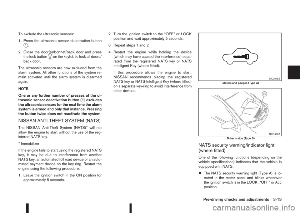
•The NATS security warning light (Type A) is lo-
cated in the meter panel and blinks whenever
the ignition switch is in the LOCK, “OFF” or Acc
position.
SIC2045ZMeters and gauges (Type A)
NIC1402ZDriver’s side (Type B)
Pre-driving checks and adjustments3-13
Page 124 of 338
•The NATS security indicator light (TypejB) is
located on the Driver’s side of the dashboard
and blinks whenever the ignition switch is in the
LOCK, “OFF” or Acc position.
If the NISSAN Anti-Theft System (NATS) is mal-
functioning, this light will remain on while the ignition
switch is in the ON position.
If the light remains on and/or the engine will not
start, see your NISSAN dealer for NATS service
as soon as possible. Please bring all NATS keys
or NATS Intelligent Keys when visiting your
NISSAN dealer for service.
Additional information for RHD models
If the NATS is malfunctioning, this light will turn on
after flashing six times while the ignition switch is in
the ON position.
However, if the NATS security warning light turns
off after the light has remained on for 15 minutes,
there is a 10 second time slot to start the engine
after the ignition is turned off. See your NISSAN
dealer for NATS service as soon as possible.
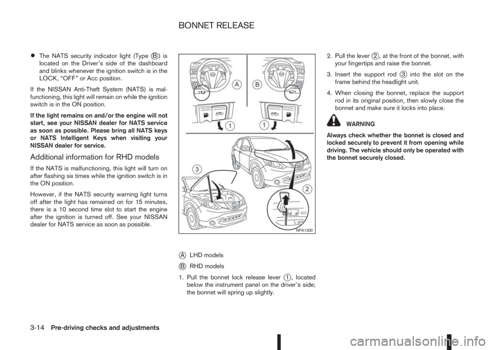
jALHD models
jBRHD models
1. Pull the bonnet lock release lever
j1 , located
below the instrument panel on the driver’s side;
the bonnet will spring up slightly.2. Pull the lever
j2 , at the front of the bonnet, with
your fingertips and raise the bonnet.
3. Insert the support rod
j3 into the slot on the
frame behind the headlight unit.
4. When closing the bonnet, replace the support
rod in its original position, then slowly close the
bonnet and make sure it locks into place.
WARNING
Always check whether the bonnet is closed and
locked securely to prevent it from opening while
driving. The vehicle should only be operated with
the bonnet securely closed.
NPA1300
BONNET RELEASE
3-14Pre-driving checks and adjustments