parking brake NISSAN QASHQAI 2017 Owner´s Manual
[x] Cancel search | Manufacturer: NISSAN, Model Year: 2017, Model line: QASHQAI, Model: NISSAN QASHQAI 2017Pages: 508, PDF Size: 2.68 MB
Page 111 of 508
2-32Instruments and controls
Check to see if the sensor area of the front
bumper is blocked. If the sensor area of the front
bumper is blocked, remove the blocking materi-
al. Restart the engine. If the warning light
continues to illuminate, have the Forward
Emergency Braking (FEB) system checked. It
is recommended that you visit a NISSAN dealer
for this service.
For more details, see “Forward Emergency
Braking (FEB)” (P.5-80) , “Forward Emergency
Braking (FEB) with pedestrian detection sys-
tem” (P.5-86) or “Intelligent Cruise Control
(ICC)” (P.5-60) .
37. Unavailable: Side Radar Obstruction
warning (if so equipped)
This warning appears when the Blind Spot
Warning (BSW)/Rear Cross Traffic Alert (RCTA)
system becomes unavailable because a radar
blockage is detected. (See “Blind Spot Warning
(BSW)” (P.5-42) or “Rear Cross Traffic Alert
(RCTA)” (P.5-51) .)
38. Press Brake Pedal warning (for
electronic parking brake equipped mod-
els)
This indicator appears in the following situa-
tions:.The driver tries to release the electronic
parking brake manually without depressing
the brake pedal.
.The vehicle is stopped on a steep hill and
there is a possibility of moving backward,
even if the electronic parking brake is
applied.
Page 126 of 508
If the ambient image sensor is damaged due to
an accident, it is recommended you contact a
NISSAN dealer.
Battery saver system
.When the headlight switch is in theorposition while the ignition switch is in
the ON position, the lights will automatically
turn off within a period of time after the
ignition switch has been placed in the OFF
position.
.When the headlight switch remains in the
orposition after the lights auto-
matically turn off, the lights will turn on when
the ignition switch is placed in the ON
position.
CAUTION
.When you turn on the headlight
switch again after the lights auto-
matically turn off, the lights will not
turn off automatically. Be sure to
turn the light switch to the OFF
position when you leave the vehicle
for extended periods of time, other-
wise the battery will be discharged.
.Never leave the light switch on
when the engine is not running forextended periods of time even if the
headlights turn off automatically.
Daytime Running Light (DRL) system
The LED portion of the headlights automatically
illuminate at 100% intensity when the engine is
started and the parking brake released. The LED
Daytime Running Light (DRL) operate with the
headlight switch in the OFF position or in the
position. When you turn the headlight
switch to theposition for full illumination,
the LED lights switch from LED DRL to the park
function.
If the parking brake is applied before the engine
is started, the LED DRL do not illuminate. The
LED DRL illuminate when the parking brake is
released. The LED DRL will remain on until the
ignition switch is placed in the OFF position.
It is necessary at dusk to turn the headlight
switch ON for interior controls and switches to
illuminate, as those remain OFF while the switch
is in the OFF position.
WARNING
When the LED DRL system is active, tail
lights on your vehicle are not on. It is
necessary at dusk to turn on yourheadlights. Failure to do so could cause
an accident injuring yourself and
others.
Instruments and controls2-47
Page 170 of 508
The following events will occur when the engine
starts:
.The front parking lights will turn on and
remain on as long as the engine is running.
.The doors will be locked and the air
conditioner system may turn on.
.The engine will continue to run for about 10
minutes. Repeat the steps to extend the time
for an additional 10 minutes. See “Extending
engine run time” (P.3-23) .
Depress and hold the brake pedal, then place
the ignition switch in the ON position before
driving. For further instructions, see “Driving the
vehicle” (P.5-20) .
EXTENDING ENGINE RUN TIME
The remote engine start function can be
extended one time by performing the steps
listed in “Remote starting the engine” (P.3-22) .
Run time will be calculated as follows:
.The first 10 minute run time will start when
the remote engine start function is per-
formed.
.The second 10 minutes will start immedi-
ately when the remote engine start function
is performed. For example, if the engine has
been running for 5 minutes, and 10 minutes
are added, the engine will run for a total of
15 minutes..Extending engine run time will count to-
wards the two remote start limit.
A maximum of two remote starts, or a single start
with an extension, are allowed between ignition
cycles.
The ignition switch must be cycled to the ON
position and then back to the OFF position
before the remote engine start procedure can be
used again.
CANCELING A REMOTE START
To cancel a remote start, perform one of the
following:
.Aim the Intelligent Key at the vehicle and
push and hold the remote engine start
button until the front parking lights turn off.
.Turn on the hazard indicator flashers.
.Cycle the ignition switch ON and then OFF.
.The extended engine run time has expired.
.The first 10 minute timer has expired.
.The engine hood has been opened.
.The shift lever is moved out of the P (Park)
position.
.The theft alarm sounds due to illegal entry
into the vehicle.
.The ignition switch is pushed without an
Intelligent Key in the vehicle..The ignition switch is pushed with an
Intelligent Key in the vehicle but the brake
pedal is not depressed.
CONDITIONS THE REMOTE ENGINE
START WILL NOT WORK
The remote engine start will not operate if any of
the following conditions are present:
.The ignition switch is placed in the ON
position.
.The hood is not securely closed.
.The hazard indicator flashers are on.
.The engine is still running. The engine must
be completely stopped. Wait at least 6
seconds if the engine goes from running to
off. This is not applicable when extending
engine run time.
.The remote engine start
button is not
pushed and held for at least 2 seconds.
.The remote engine start
button is not
pushed and held within 5 seconds of
pushing the LOCK
button.
.The brake pedal is depressed.
.The doors are not closed and locked.
.The liftgate is open.
.The Key System Error warning message
remains on in the vehicle information display.
.An Intelligent Key is left inside the vehicle.
Pre-driving checks and adjustments3-23
Page 192 of 508
SAA3475
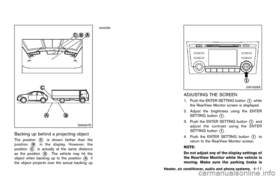
Backing up behind a projecting object
The position*Cis shown farther than the
position
*Bin the display. However, the
position
*Cis actually at the same distance
as the position
*A. The vehicle may hit the
object when backing up to the position
*Aif
the object projects over the actual backing upcourse.
JVH1626X
ADJUSTING THE SCREEN
1. Push the ENTER SETTING button*1while
the RearView Monitor screen is displayed.
2. Adjust the brightness using the ENTER
SETTING button
*1.
3. Push the ENTER SETTING button
*1and
adjust the contrast using the ENTER
SETTING button
*1.
4. Push the ENTER SETTING button
*1to
return to the RearView Monitor screen.
NOTE:
Do not adjust any of the display settings of
the RearView Monitor while the vehicle is
moving. Make sure the parking brake is
Heater, air conditioner, audio and phone systems4-11
Page 202 of 508
5. When the vehicle is parked in the space
completely, move the shift lever to the P
(Park) position and apply the parking brake.
HOW TO SWITCH THE DISPLAY
With the ignition switch placed in the ACC or
ON position, push the CAMERA button or move
the shift lever to the R (Reverse) position to
operate the Around View
�ŠMonitor.
The Around View�ŠMonitor displays different
split screen views depending on the position of
the shift lever. Push the CAMERA button to
switch between the available views.
If the shift lever is in the R (Reverse) position, the
available views are:
.Rear view/bird’s-eye view split screen
.Rear view/front-side view split screen
.Rear view
If the shift lever is in the P (Park) position, the
available views are:
.Front view/bird’s-eye view split screen
.Front view/front-side view split screen
The display will switch from the Around View
�Š
Monitor screen when:
.The shift lever is in the D (Drive) position and
the vehicle speed increases above approxi-
mately 6 MPH (10 km/h) ..A different screen is selected.
JVH1636X
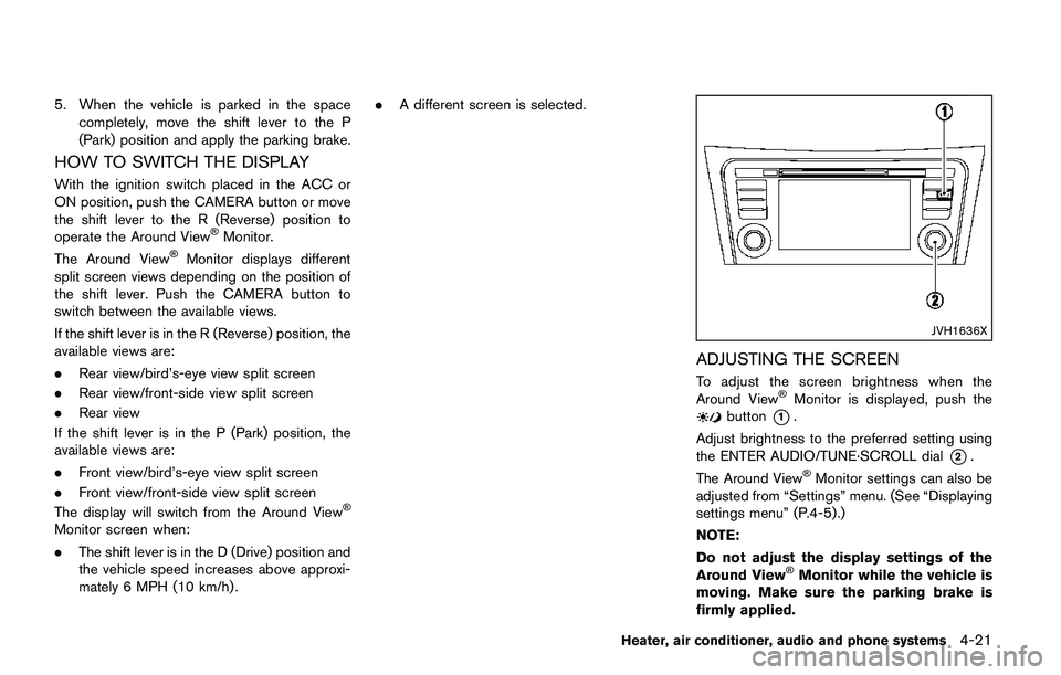
ADJUSTING THE SCREEN
To adjust the screen brightness when the
Around View�ŠMonitor is displayed, push thebutton*1.
Adjust brightness to the preferred setting using
the ENTER AUDIO/TUNE·SCROLL dial
*2.
The Around View�ŠMonitor settings can also be
adjusted from “Settings” menu. (See “Displaying
settings menu” (P.4-5) .)
NOTE:
Do not adjust the display settings of the
Around View
�ŠMonitor while the vehicle is
moving. Make sure the parking brake is
firmly applied.
Heater, air conditioner, audio and phone systems4-21
Page 286 of 508
5 Starting and driving
Precautions when starting and driving ................................ 5-4
Exhaust gas (carbon monoxide) ...................................... 5-4
Three-way catalyst .............................................................. 5-5
Tire Pressure Monitoring System (TPMS) .................... 5-5
Avoiding collision and rollover ......................................... 5-8
On-pavement and off-road driving precautions .......... 5-8
Off-road recovery ................................................................ 5-9
Rapid air pressure loss ...................................................... 5-9
Drinking alcohol/drugs and driving .............................. 5-10
Driving safety precautions .............................................. 5-10
Ignition switch (models without Intelligent
Key system) ............................................................................. 5-12
Continuously Variable Transmission (CVT) ................ 5-13
Manual Transmission (MT) ............................................. 5-13
Key positions ..................................................................... 5-14
Push-button ignition switch (model with Intelligent
Key system) ............................................................................. 5-14
Operating range for engine start function ................. 5-14
Push-button ignition switch operation ........................ 5-15
Push-button ignition switch positions ......................... 5-16
Emergency engine shut off ............................................ 5-16
Intelligent Key battery discharge .................................. 5-16
Before starting the engine ................................................... 5-17
Starting the engine (model without Intelligent
Key system) ............................................................................. 5-17Starting the engine (model with Intelligent
Key system) ............................................................................ 5-18
Remote engine start (if so equipped) ...................... 5-19
Driving the vehicle ................................................................. 5-20
Continuously Variable Transmission (CVT) ............. 5-20
Manual Transmission (MT) ........................................... 5-25
Parking brake .......................................................................... 5-26
Pedal type ........................................................................ 5-27
Switch type (models with electronic parking
brake system) ................................................................. 5-27
ECO mode system ............................................................... 5-29
ECO Pedal Guide function ......................................... 5-29
Ambient ECO .................................................................. 5-30
ECO Drive Report ......................................................... 5-31
Lane Departure Warning (LDW) (if so equipped) ....... 5-31
LDW system operation ................................................. 5-32
How to enable/disable the LDW system ................. 5-33
LDW system limitations ................................................ 5-34
System temporarily unavailable .................................. 5-35
System malfunction ....................................................... 5-35
System maintenance ..................................................... 5-36
Lane Departure Prevention (LDP) (if so equipped) ..... 5-36
LDP system operation .................................................. 5-37
How to enable/disable the LDP system .................. 5-38
LDP system limitations ................................................. 5-39
Page 287 of 508
System temporarily unavailable ..................................... 5-40
System malfunction .......................................................... 5-41
System maintenance ....................................................... 5-41
Blind Spot Warning (BSW) (if so equipped) ................. 5-42
BSW system operation .................................................. 5-43
How to enable/disable the BSW system .................. 5-44
BSW system limitations ................................................. 5-45
BSW driving situations ................................................... 5-46
System temporarily unavailable ..................................... 5-49
System malfunction .......................................................... 5-49
System maintenance ....................................................... 5-50
Rear Cross Traffic Alert (RCTA) (if so equipped) ......... 5-51
RCTA system operation .................................................. 5-51
How to enable/disable the RCTA system ................. 5-53
RCTA system limitations ................................................. 5-54
System temporarily unavailable ..................................... 5-56
System malfunction .......................................................... 5-56
System maintenance ....................................................... 5-57
Cruise control (if so equipped) .......................................... 5-58
Precautions on cruise control ....................................... 5-58
Cruise control operations ............................................... 5-58
Intelligent Cruise Control (ICC) (if so equipped) .......... 5-60
How to select the cruise control mode ...................... 5-62
Vehicle-to-vehicle distance control mode .................. 5-62
Conventional (fixed speed) cruise control mode ..... 5-76
Forward Emergency Braking (FEB) (if so equipped) ..... 5-80
FEB system operation ..................................................... 5-81
Turning the FEB system ON/OFF ................................ 5-82
FEB system limitations .................................................... 5-83System temporarily unavailable .................................. 5-84
System malfunction ....................................................... 5-85
System maintenance ..................................................... 5-85
Forward Emergency Braking (FEB) with pedestrian
detection system ................................................................... 5-86
FEB with pedestrian detection
system operation ............................................................ 5-87
Turning the FEB with pedestrian detection
system ON/OFF ............................................................. 5-89
FEB with pedestrian detection
system limitations ........................................................... 5-89
System temporarily unavailable .................................. 5-92
System malfunction ....................................................... 5-93
System maintenance ..................................................... 5-94
Break-in schedule ................................................................. 5-95
Fuel Efficient Driving Tips ................................................... 5-95
Increasing fuel economy ...................................................... 5-96
All-Wheel Drive (AWD) (if so equipped) ........................ 5-96
AWD LOCK switch operations .................................. 5-98
Parking/parking on hills ..................................................... 5-100
Electric power steering ..................................................... 5-101
Brake system ....................................................................... 5-102
Braking precautions ................................................... 5-102
Brake assist ......................................................................... 5-102
Brake assist .................................................................. 5-102
Anti-lock Braking System (ABS) ............................ 5-102
Vehicle Dynamic Control (VDC) system ...................... 5-104
Chassis control ................................................................... 5-106
Active Trace Control .................................................. 5-106
Page 292 of 508
for approximately 1 minute. The
light will remain on after 1 minute.
Have your tires replaced and/or
TPMS system reset as soon as
possible. It is recommended you
visit a NISSAN dealer for these
services.
.Replacing tires with those not ori-
ginally specified by NISSAN could
affect the proper operation of the
TPMS.
.Do not inject any tire liquid or
aerosol tire sealant into the tires,
as this may cause a malfunction of
the tire pressure sensors.
CAUTION
.The TPMS may not function properly
when the wheels are equipped with
tire chains or the wheels are buried
in snow.
.Do not place metalized film or any
metal parts (antenna, etc.) on the
windows. This may cause poor re-
ception of the signals from the tire
pressure sensors, and the TPMS willnot function properly.
Some devices and transmitters may temporarily
interfere with the operation of the TPMS and
cause the low tire pressure warning light to
illuminate. Some examples are:
.Facilities or electric devices using similar
radio frequencies are near the vehicle.
.If a transmitter set to similar frequencies is
being used in or near the vehicle.
.If a computer (or similar equipment) or a DC/
AC converter is being used in or near the
vehicle.
Low tire pressure warning light may illuminate in
the following cases.
.If the vehicle is equipped with a wheel and
tire without TPMS.
.If the TPMS has been replaced and the ID
has not been registered.
.If the wheel is not originally specified by
NISSAN.
FCC Notice:
For USA:
This device complies with Part 15 of the
FCC Rules. Operation is subject to the
following two conditions: (1) This device
may not cause harmful interference, and
(2) this device must accept any interfer-ence received, including interference that
may cause undesired operation.
Note: Changes or modifications not ex-
pressly approved by the party responsible
for compliance could void the user’s
authority to operate the equipment.
For Canada:
This device complies with Industry Canada
licence-exempt RSS standard(s) . Opera-
tion is subject to the following two condi-
tions: (1) this device may not cause
interference, and (2) this device must
accept any interference, including interfer-
ence that may cause undesired operation
of the device.
TPMS with Easy Fill Tire Alert
When adding air to an under-inflated tire, the
TPMS with Easy Fill Tire Alert provides visual
and audible signals outside the vehicle to help
you inflate the tires to the recommended COLD
tire pressure.
Vehicle set-up:
1. Park the vehicle in a safe and level place.
2. Apply the parking brake and place the shift
lever in the P (Park) position (CVT model) or
N (Neutral) position (MT model) .
Starting and driving5-7
Page 297 of 508
5-12Starting and driving
passenger car. The vehicle is not
designed for cornering at the same
speeds as conventional passenger
cars. Failure to operate this vehicle
correctly could result in loss of
control and/or a rollover accident.
.Always use tires of the same type,
size, brand, construction (bias, bias-
belted or radial) , and tread pattern
on all four wheels. Install traction
devices on the front wheels when
driving on slippery roads and drive
carefully.
.Be sure to check the brakes imme-
diately after driving in mud or water.
See“Brake system”(P.5-102) for wet
brakes.
.Avoid parking your vehicle on steep
hills. If you get out of the vehicle
and it rolls forward, backward or
sideways, you could be injured.
.Whenever you drive off-road
through sand, mud or water as deep
as the wheel hub, more frequent
maintenance may be required. See
the maintenance schedule shown in
the“9. Maintenance and schedules”
section..Spinning the front wheels on slip-
pery surfaces may cause the AWD
warning message to display and the
AWD system to automatically switch
from the AWD mode to the 2WD
mode. This could reduce traction.
(AWD models)WARNING
Never remove the key or place the
ignition switch in the LOCK position
while driving. The steering wheel will
lock and could cause the driver to lose
control of the vehicle. This could result
in serious vehicle damage or personal
injury.
IGNITION SWITCH (models without
Intelligent Key system)
Page 301 of 508
5-16Starting and driving
PUSH-BUTTON IGNITION SWITCH
POSITIONS
LOCK (Normal parking position)
The ignition switch can only be locked at this
position.
The ignition switch will lock when any door is
opened or closed with the ignition switched off.
ON (Normal operating position)
The ignition system and the electrical accessory
power activate at this position without the
engine turned on.
The ON position has a battery saver feature that
will place the ignition switch in the OFF position,
if the vehicle is not running, after some time
under the following conditions:
.all doors are closed.
.shift lever is in P (Park) position (CVT model)
or N (Neutral) position (MT model) .
The battery saver feature will be cancelled if any
of the following occur:
.any door is opened.
.shift lever is moved out of the P (Park)
position (CVT model) .
.ignition switch changes position.
OFF position
The engine is turned off in this position.
Auto ACC position
With the vehicle in the P (Park) position (CVT
models) or the N (Neutral) position (MT models) ,
the Intelligent Key with you and the ignition
placed from ON to OFF, the radio can still be
used for a period of time, or until the driver’s
door is opened. After a period of time, functions
such as radio, navigation (if so equipped) , and
Bluetooth
�ŠHands-Free Phone System may be
restarted by turning on the audio system (See
“Audio system” (P.4-38) in this manual) , or by
the UNLOCK button on the Intelligent Key for up
to a total of 30 minutes.
EMERGENCY ENGINE SHUT OFF
To shut off the engine in an emergency situation
while driving, perform the following procedure:
.Rapidly push the push-button ignition switch
3 consecutive times in less than 1.5
seconds, or
.Push and hold the push-button ignition
switch for more than 2 seconds.
JVS0404X
INTELLIGENT KEY BATTERY DIS-
CHARGE
If the battery of the Intelligent Key is discharged,
or environmental conditions interfere with the
Intelligent Key operation, start the engine
according to the following procedure:
1. Move the shift lever to the P (Park) position
(for CVT models) or the shift lever to the N
(Neutral) position (for MT models) .
2. Firmly apply the foot brake.
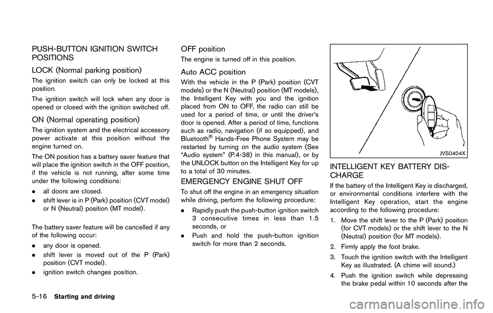
3. Touch the ignition switch with the Intelligent
Key as illustrated. (A chime will sound.)
4. Push the ignition switch while depressing
the brake pedal within 10 seconds after the