sensor NISSAN QASHQAI 2023 User Guide
[x] Cancel search | Manufacturer: NISSAN, Model Year: 2023, Model line: QASHQAI, Model: NISSAN QASHQAI 2023Pages: 508, PDF Size: 2.47 MB
Page 81 of 508
REPAIR AND REPLACEMENT PRO-
CEDURE
The front air bags, knee air bags, side air
bags, curtain air bags and pretensioners
are designed to activate on a one-time-
only basis. As a reminder, unless it is
damaged, the supplemental air bag
warning light will remain illuminated after
inflation has occurred. These systems
should be repaired and/or replaced as
soon as possible. It is recommended you
visit a NISSAN dealer for this service.
When maintenance work is required on
the vehicle, the front air bags, knee air
bags, side air bags, curtain air bags and
pretensioners and related parts should be
pointed out to the person performing the
maintenance. The ignition switch should
always be in the LOCK position when
working under the hood or inside the
vehicle.
WARNING
.Once a front air bag, knee air bag,
side air bag or curtain air bag has
inflated, the air bag module will
not function again and must be
replaced. Additionally, the acti-
vated pretensioners must also
be replaced. The air bag module and pretensioner should be re-
placed. It is recommended you
visit a NISSAN dealer for this
service. However, the air bag
modules and pretensioner sys-
tem cannot be repaired.
. The front air bag, knee air bag,
side air bag and curtain air bag
systems, and pretensioner sys-
tem should be inspected if there
is any damage to the front end or
side portion of the vehicle. It is
recommended you visit a NISSAN
dealer for this service.
. If you need to dispose of a sup-
plemental air bag or pretensioner
or scrap the vehicle, it is recom-
mended you visit a NISSAN deal-
er. Correct supplemental air bag
and pretensioner system dispo-
sal procedures are set forth in the
appropriate NISSAN Service Man-
ual. Incorrect disposal procedures
could cause personal injury.
. If there is an impact to your
vehicle from any direction, your
Occupant Classification Sensor
(OCS) should be checked to verify
it is still functioning correctly. It is
recommended that you visit a
NISSAN dealer for this service.
The OCS should be checked even if no air bags deploy as a result of
the impact. Failure to verify prop-
er OCS function may result in an
improper air bag deployment re-
sulting in injury or death.
Safety — Seats, seat belts and supplemental restraint system1-63
Page 103 of 508
SETTINGS
The setting mode allows you to change
the information displayed in the vehicle
information display:
.Driver Assistance
. Clock
. Meter Settings
. Vehicle Settings
. Maintenance
. Alarm (if so equipped)
. Tire Pressures
. Unit
. Language
. Factory Reset
Driver Assistance
To change the status, warnings or turn on
or off any of the systems/warnings dis-
played in the “Driver Assistance” menu,
use the
buttonsto select and the
OKto change a menu item:
. Driving Aids
. Parking Aids (if so equipped)
. Chassis Control (if so equipped)
. Driver Attention (if so equipped)
. Speed Limit Sign (if so equipped)
Driving Aids:
To change the status, warnings or turn on
or off any of the systems/warnings dis- played in the “Driving Aids” menu, use the
buttonsto select and the OKto
change a menu item:
. Steering Assist (if so equipped)
Allows user to turn the Steering Assist
ON/OFF.
. Emergency Brake
— Front
Allows user to turn the Automatic
Emergency Braking (AEB) with Pe-
destrian Detection system and In-
telligent Forward Collision Warning
(I-FCW) system ON/OFF
— Rear Allows user to turn the Rear Auto-
matic Braking (RAB) system ON/
OFF.
. Lane
— Warning (LDW)
Allows user to turn the Lane De-
parture Warning (LDW) system ON/
OFF.
— Prevention (LDP) Allows user to turn the Intelligent
Lane Intervention (I-LI) system ON/
OFF.
. Blind Spot
— Warning (BSW)
Allows user to turn the Blind Spot
Warning (BSW) system ON/OFF.
For additional information, see “ProPILOT assist” (P.5-64), “Automatic Emergency
Braking (AEB) with Pedestrian Detection
system” (P.5-97), “Rear Automatic Braking
(RAB)” (P.5-116), “Lane Departure Warning
(LDW)” (P.5-35), “Intelligent Lane Interven-
tion (I-LI)” (P.5-86), and “Blind Spot Warn-
ing (BSW)” (P.5-46).
Parking Aids (if so equipped):
To change the status or turn on or off any
of the systems displayed in the “Parking
Aids” menu, use the
buttonsto
select and the OKto change a menu
item:
. Moving Object (if so equipped)
Press the OK
to turn the Moving
Object Detection (MOD) ON/OFF.
. Cross Traffic
Press the OK
to turn the Rear Cross
Traffic Alert (RCTA) ON/OFF.
. Rear Sensor (if so equipped)
Allows user to turn the rear sensor
ON/OFF.
. Display (if so equipped)
Allows user to turn the Rear Sonar
System (RSS) display ON/OFF.
. Volume (if so equipped)
Allows user to select sensor volume
(High, Med. or Low).
. Range (if so equipped)
Allows user to select the sensor range
Instruments and controls2-21
Page 116 of 508
2-34Instruments and controls
26. Timer Alert — Time for a driver
break? indicator
This indicator appears when the set “Time
for a driver break?” indicator activates.
You can set the time for up to 6 hours.
27. Chassis Control System Error:
See Owner’s Manual warning
This warning appears if the chassis con-
trol module detects an error in the
chassis control system. Have the system
checked. It is recommended that you visit
a NISSAN dealer for this service. (See
“Chassis control” (P.5-133).)
28. Cruise control indicator (if so
equipped)
This indicator shows the cruise control
system status. The status is shown by the
color.
See “Cruise control” (P.5-62) for details.
29. Intelligent Cruise Control (ICC)
indicator (if so equipped)
This indicator shows the Intelligent Cruise
Control (ICC) system status. The status is
shown by the color. (See “Intelligent
Cruise Control (ICC)” (P.5-75).)
30. Continuously Variable Trans-
mission (CVT) position indicator
(CVT models)
This indicator shows the automatic shift
position.
In the manual shift mode, when the
transmission does not shift to the se-
lected gear due to a transmission protec-
tion mode, the CVT position indicator will
blink and a chime will sound.
See “Continuously Variable Transmission
(CVT)” (P.5-20) for further details.
31. CVT Error: See Owner’s Manual
warning (CVT models)
This warning appears when there is a
malfunction with the CVT system. If this
warning comes on, have the system
checked. It is recommended that you visit
a NISSAN dealer for this service.
32 Malfunction warning
This warning appears when the following
systems malfunction.
.Lane Departure Warning (LDW)
. Intelligent Lane Intervention (I-LI)
. Blind Spot Warning (BSW)
. Rear Cross Traffic Alert (RCTA)
. Automatic Emergency Braking (AEB)
with Pedestrian Detection .
Intelligent Forward Collision Warning
(I-FCW)
. Rear Automatic Braking (RAB)
For more details, see “Lane Departure
Warning (LDW)” (P.5-35), “Intelligent Lane
Intervention (I-LI)” (P.5-40), “Blind Spot
Warning (BSW)” (P.5-46), “Rear Cross Traf-
fic Alert (RCTA)” (P.5-54), “ProPILOT assist”
(P.5-64), “Automatic Emergency Braking
(AEB) with Pedestrian Detection system”
(P.5-97), “Intelligent Forward Collision
Warning (I-FCW)” (P.5-107) or “Rear Auto-
matic Braking (RAB)” (P.5-116).
33. Drive mode indicators
These indicators illuminate in the vehicle
information display when either the ECO
or SPORT mode is selected.
For additional information, refer to
“SPORT mode switch” (P.5-32) or “ECO
mode system” (P.5-32).
34. Unavailable: High Cabin Tem-
perature warning
This warning appears if the interior tem-
perature of the vehicle has reached such
a high temperature that the sensor for
the Lane Departure Warning (LDW), Intel-
ligent Lane Intervention (I-LI) or Traffic
Sign Recognition (TSR) (if so equipped)
system can no longer function reliably.
Once the interior temperature has
Page 117 of 508
reached normal levels, the warning
should disappear.
If the warning continues to display, have
the system checked. It is recommended
that you visit a NISSAN dealer for this
service.
For additional information, refer to “Lane
Departure Warning (LDW)” (P.5-35), “Intel-
ligent Lane Intervention (I-LI)” (P.5-86) or
“Traffic Sign Recognition” (P.2-43).
35. Not Available: Poor Road Con-
ditions warning (if so equipped)
This message appears when the Intelli-
gent Lane Intervention (I-LI) system or the
Intelligent Cruise Control (ICC) system
becomes unavailable because the road
is slippery. See “Intelligent Lane Interven-
tion (I-LI)” (P.5-40) or “Intelligent Cruise
Control (ICC)” (P.5-75).
36. Currently unavailable warning
This message appears when the Intelli-
gent Lane Intervention (I-LI) system or the
Intelligent Cruise Control (ICC) system
becomes unavailable because the VDC is
turned off or operates. For additional
information, refer to “Intelligent Lane
Intervention (I-LI)” (P.5-40) or “Intelligent
Cruise Control (ICC)” (P.5-75).
37. Forward Driving Aids Tempora-
rily Disabled Front Sensor Blocked/
Unavailable: Front Radar Obstruc-
tion warning
This message appears when the front
radar sensor may be obstructed due to:
.mud, dirt, snow, ice, etc.
. inclement weather (rain, fog, snow,
etc)
All forward driving aids are temporarily
disabled until the system detects that the
front radar sensor is no longer ob-
structed.
See “Automatic Emergency Braking (AEB)
with Pedestrian Detection system” (P.5-
97), “Intelligent Forward Collision Warning
(I-FCW)” (P.5-107) or “ProPILOT assist” (P.5-
64).
38. Unavailable: Side Radar Ob-
struction warning
This warning appears when the Blind
Spot Warning (BSW)/Rear Cross Traffic
Alert (RCTA) system becomes unavailable
because a radar blockage is detected.
(See “Blind Spot Warning (BSW)” (P.5-46) or
“Rear Cross Traffic Alert (RCTA)” (P.5-54).)
39. Press Brake Pedal warning (for
electronic parking brake equipped
models)
This indicator appears in the following
situations:
. The driver tries to release the electro-
nic parking brake manually without
depressing the brake pedal.
. The vehicle is stopped on a steep hill
and there is a possibility of moving
backward, even if the electronic park-
ing brake is applied.
. This warning appears if the vehicle
moves while the automatic brake hold
(if so equipped) is activated.
40. Lane Departure Warning (LDW)/
Intelligent Lane Intervention (I-LI)
indicator
This indicator shows when the LDW and/
or I-LI systems are engaged.
See “Lane Departure Warning (LDW)” (P.5-
35) or “Intelligent Lane Intervention (I-LI)”
(P.5-40).
Instruments and controls2-35
Page 120 of 508
2-38Instruments and controls
53. Press brake pedal to operate
switch warning (if so equipped)
This warning appears if the automatic
brake hold switch is pushed without
depressing the brake pedal while the
automatic brake hold function is acti-
vated. Depress the brake pedal and push
the switch to deactivate the automatic
brake hold function. For more details, see
“Automatic brake hold” (P.5-29).
54. AUTO HOLD Caution Steep
Slope indicator (if so equipped)
This indicator appears when the auto-
matic brake hold function is activated
while the vehicle is on a steep hill.
55. Steep Slope Apply Foot Brake to
hold vehicle warning (if so
equipped)
This warning appears before the electro-
nic parking brake is applied and the brake
force of the automatic brake hold func-
tion is released when the vehicle is on a
steep hill, to prevent the vehicle rolls out.
56. Intelligent Driver Alertness (I-DA)
malfunction warning (if so
equipped)
This warning appears when the Intelli-
gent Driver Alertness (I-DA) system mal-
functions. See “Intelligent Driver Alertness
(I-DA)” (P.5-94).
57. Traffic Sign Recognition mal-
function warning (if so equipped)
This warning appears when the Traffic
Sign Recognition system malfunctions.
For more details, see “Traffic Sign Recog-
nition” (P.2-43).
58. Parking Sensor Error warning (if
so equipped)
This warning illuminates when there is a
malfunction with the Rear Sonar System
(RSS). For additional information, refer to
“Rear Sonar System (RSS)” (P.5-136).
Page 125 of 508
Outside air temperature (°F or °C)
The outside air temperature is displayed
in °F or °C in the range of −40 to 140°F (−40
to 60°C).
The outside air temperature mode in-
cludes a low temperature warning fea-
ture. If the outside air temperature is
below 37°F (3°C), the warning
is dis-
played (if so equipped).
The outside temperature sensor is lo-
cated in front of the radiator. The sensor
may be affected by road or engine heat,
wind directions and other driving condi-
tions. The display may differ from the
actual outside temperature or the tem-
perature displayed on various signs or
billboards.
WAC0198X
TRAFFIC SIGN RECOGNITION (if so
equipped)
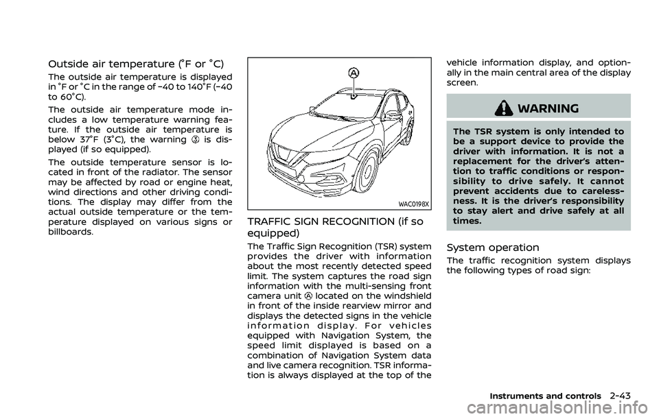
The Traffic Sign Recognition (TSR) system
provides the driver with information
about the most recently detected speed
limit. The system captures the road sign
information with the multi-sensing front
camera unit
located on the windshield
in front of the inside rearview mirror and
displays the detected signs in the vehicle
information display. For vehicles
equipped with Navigation System, the
speed limit displayed is based on a
combination of Navigation System data
and live camera recognition. TSR informa-
tion is always displayed at the top of the vehicle information display, and option-
ally in the main central area of the display
screen.
WARNING
The TSR system is only intended to
be a support device to provide the
driver with information. It is not a
replacement for the driver’s atten-
tion to traffic conditions or respon-
sibility to drive safely. It cannot
prevent accidents due to careless-
ness. It is the driver’s responsibility
to stay alert and drive safely at all
times.
System operation
The traffic recognition system displays
the following types of road sign:
Instruments and controls2-43
Page 136 of 508
2-54Instruments and controls
lights are on), the headlights will remain
on for 5 minutes when the ignition switch
is placed in the OFF position and one of
the doors is opened.
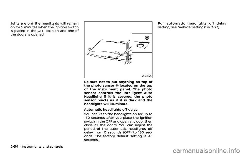
JVI0510X
Be sure not to put anything on top of
the photo sensorlocated on the top
of the instrument panel. The photo
sensor controls the Intelligent Auto
Headlight; if it is covered, the photo
sensor reacts as if it is dark and the
headlights will illuminate.
Automatic headlights off delay:
You can keep the headlights on for up to
180 seconds after you place the ignition
switch in the OFF and open any door then
close all the doors. You can adjust the
period of the automatic headlights off
delay from 0 seconds (OFF) to 180 sec-
onds. The factory default setting is 45
seconds. For automatic headlights off delay
setting, see “Vehicle Settings” (P.2-23).
Page 139 of 508
WAC0198X
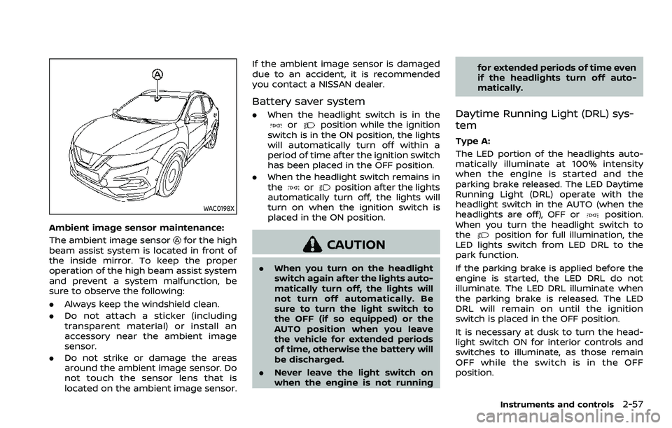
Ambient image sensor maintenance:
The ambient image sensor
for the high
beam assist system is located in front of
the inside mirror. To keep the proper
operation of the high beam assist system
and prevent a system malfunction, be
sure to observe the following:
. Always keep the windshield clean.
. Do not attach a sticker (including
transparent material) or install an
accessory near the ambient image
sensor.
. Do not strike or damage the areas
around the ambient image sensor. Do
not touch the sensor lens that is
located on the ambient image sensor. If the ambient image sensor is damaged
due to an accident, it is recommended
you contact a NISSAN dealer.
Battery saver system
.
When the headlight switch is in theorposition while the ignition
switch is in the ON position, the lights
will automatically turn off within a
period of time after the ignition switch
has been placed in the OFF position.
. When the headlight switch remains in
the
orposition after the lights
automatically turn off, the lights will
turn on when the ignition switch is
placed in the ON position.
CAUTION
. When you turn on the headlight
switch again after the lights auto-
matically turn off, the lights will
not turn off automatically. Be
sure to turn the light switch to
the OFF (if so equipped) or the
AUTO position when you leave
the vehicle for extended periods
of time, otherwise the battery will
be discharged.
. Never leave the light switch on
when the engine is not running for extended periods of time even
if the headlights turn off auto-
matically.
Daytime Running Light (DRL) sys-
tem
Type A:
The LED portion of the headlights auto-
matically illuminate at 100% intensity
when the engine is started and the
parking brake released. The LED Daytime
Running Light (DRL) operate with the
headlight switch in the AUTO (when the
headlights are off), OFF or
position.
When you turn the headlight switch to
the
position for full illumination, the
LED lights switch from LED DRL to the
park function.
If the parking brake is applied before the
engine is started, the LED DRL do not
illuminate. The LED DRL illuminate when
the parking brake is released. The LED
DRL will remain on until the ignition
switch is placed in the OFF position.
It is necessary at dusk to turn the head-
light switch ON for interior controls and
switches to illuminate, as those remain
OFF while the switch is in the OFF
position.
Instruments and controls2-57
Page 203 of 508
indicator light will turn off. Push the “I”
switchto turn the system on.
Do not allow any object to cover the
sensors
or apply glass cleaner on
them. Doing so will reduce the sensitiv-
ity of the sensor, resulting in improper
operation.
For the HomeLink® Universal Transceiver
operation, see “HomeLink® Universal
Transceiver” (P.2-83).
OUTSIDE MIRRORS
WARNING
Objects viewed in the outside mirror
on the passenger side are closer
than they appear. Be careful when
moving to the right. Using only this
mirror could cause an accident. Use
the inside mirror or glance over your
shoulder to properly judge distances
to other objects.
JVP0395X
Adjusting outside mirrors
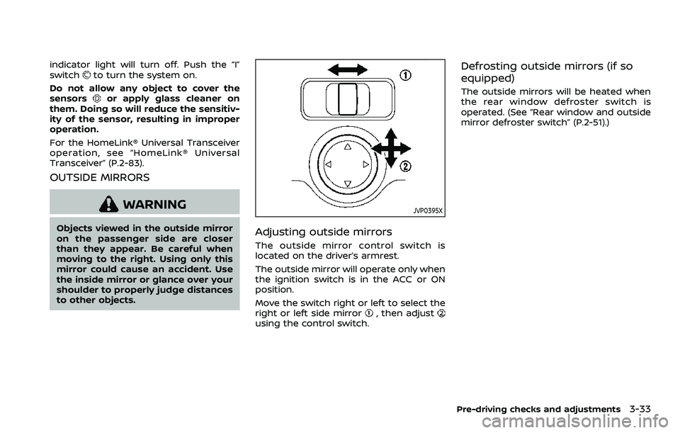
The outside mirror control switch is
located on the driver’s armrest.
The outside mirror will operate only when
the ignition switch is in the ACC or ON
position.
Move the switch right or left to select the
right or left side mirror
, then adjustusing the control switch.
Defrosting outside mirrors (if so
equipped)
The outside mirrors will be heated when
the rear window defroster switch is
operated. (See “Rear window and outside
mirror defroster switch” (P.2-51).)
Pre-driving checks and adjustments3-33
Page 239 of 508
OPERATING TIPS (for automatic air
conditioner)
When the engine coolant temperature
and outside air temperature are low, the
air flow from the foot outlets may not
operate for a maximum of 150 seconds.
However, this is not a malfunction. After
the coolant temperature warms up, air
flow from the foot outlets will operate
normally.
The sensors
and, located on the
instrument panel, help maintain a con-
stant temperature. Do not put anything
on or around the sensors.
SERVICING AIR CONDITIONER
WARNING
The air conditioner system contains
refrigerant under high pressure. To
avoid personal injury, any air condi-
tioner service should be done only by
an experienced technician with the
proper equipment.
The air conditioner system in your vehicle
is charged with a refrigerant designed
with the environment in mind.
This refrigerant will not harm the
earth’s ozone layer. However, it maycontribute in a small part to global
warming.
Special charging equipment and lubricant
are required when servicing your vehicle’s
air conditioner. Using improper refriger-
ants or lubricants will cause severe da-
mage to the air conditioner system. (See
“Air conditioning system refrigerant and
oil recommendations” (P.10-6).)
A NISSAN dealer will be able to service
your environmentally friendly air condi-
tioner system.
In-cabin microfilter
The air conditioner system is equipped
with an in-cabin microfilter. To make sure
the air conditioner heats, defogs, and
ventilates efficiently, replace the filter
according to the specified maintenance
intervals listed in the "9. Maintenance and
schedules" section. It is recommended to
visit a NISSAN dealer to replace the filter.
The filter should be replaced if the air flow
decreases significantly or if windows fog
up easily when operating the heater or air
conditioner.SAA2374
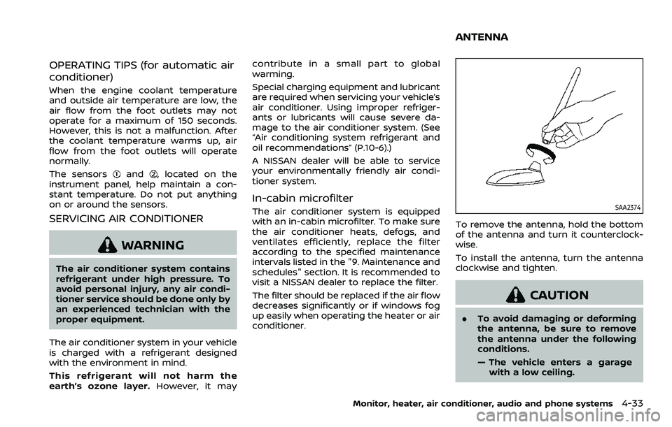
To remove the antenna, hold the bottom
of the antenna and turn it counterclock-
wise.
To install the antenna, turn the antenna
clockwise and tighten.
CAUTION
.
To avoid damaging or deforming
the antenna, be sure to remove
the antenna under the following
conditions.
— The vehicle enters a garage
with a low ceiling.
Monitor, heater, air conditioner, audio and phone systems4-33
ANTENNA