sensor NISSAN QASHQAI 2023 Workshop Manual
[x] Cancel search | Manufacturer: NISSAN, Model Year: 2023, Model line: QASHQAI, Model: NISSAN QASHQAI 2023Pages: 508, PDF Size: 2.47 MB
Page 353 of 508
.Excessive noise will interfere with
the warning chime sound, and
the chime may not be heard.
SSD0253
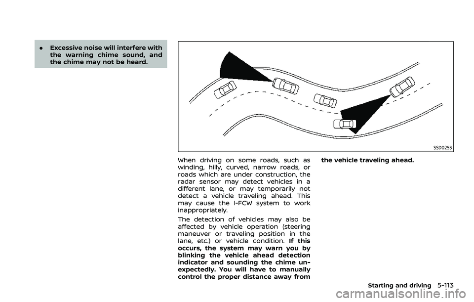
When driving on some roads, such as
winding, hilly, curved, narrow roads, or
roads which are under construction, the
radar sensor may detect vehicles in a
different lane, or may temporarily not
detect a vehicle traveling ahead. This
may cause the I-FCW system to work
inappropriately.
The detection of vehicles may also be
affected by vehicle operation (steering
maneuver or traveling position in the
lane, etc.) or vehicle condition. If this
occurs, the system may warn you by
blinking the vehicle ahead detection
indicator and sounding the chime un-
expectedly. You will have to manually
control the proper distance away from the vehicle traveling ahead.
Starting and driving5-113
Page 354 of 508
5-114Starting and driving
JVS0972X
SYSTEM TEMPORARILY UNAVAIL-
ABLE
Condition A
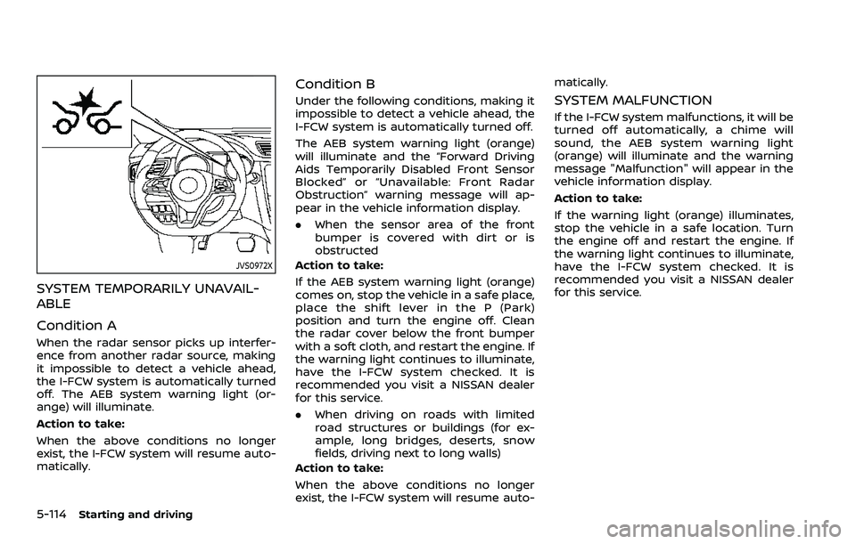
When the radar sensor picks up interfer-
ence from another radar source, making
it impossible to detect a vehicle ahead,
the I-FCW system is automatically turned
off. The AEB system warning light (or-
ange) will illuminate.
Action to take:
When the above conditions no longer
exist, the I-FCW system will resume auto-
matically.
Condition B
Under the following conditions, making it
impossible to detect a vehicle ahead, the
I-FCW system is automatically turned off.
The AEB system warning light (orange)
will illuminate and the “Forward Driving
Aids Temporarily Disabled Front Sensor
Blocked” or “Unavailable: Front Radar
Obstruction” warning message will ap-
pear in the vehicle information display.
.When the sensor area of the front
bumper is covered with dirt or is
obstructed
Action to take:
If the AEB system warning light (orange)
comes on, stop the vehicle in a safe place,
place the shift lever in the P (Park)
position and turn the engine off. Clean
the radar cover below the front bumper
with a soft cloth, and restart the engine. If
the warning light continues to illuminate,
have the I-FCW system checked. It is
recommended you visit a NISSAN dealer
for this service.
. When driving on roads with limited
road structures or buildings (for ex-
ample, long bridges, deserts, snow
fields, driving next to long walls)
Action to take:
When the above conditions no longer
exist, the I-FCW system will resume auto- matically.SYSTEM MALFUNCTION
If the I-FCW system malfunctions, it will be
turned off automatically, a chime will
sound, the AEB system warning light
(orange) will illuminate and the warning
message "Malfunction" will appear in the
vehicle information display.
Action to take:
If the warning light (orange) illuminates,
stop the vehicle in a safe location. Turn
the engine off and restart the engine. If
the warning light continues to illuminate,
have the I-FCW system checked. It is
recommended you visit a NISSAN dealer
for this service.
Page 355 of 508
WAF0285X
SYSTEM MAINTENANCE
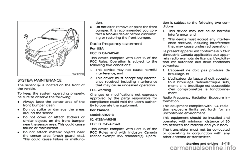
The sensoris located on the front of
the vehicle.
To keep the system operating properly,
be sure to observe the following:
. Always keep the sensor area of the
front bumper clean.
. Do not strike or damage the areas
around the sensor.
. Do not cover or attach stickers or
similar objects on the front bumper
near the sensor area. This could cause
failure or malfunction.
. Do not attach metallic objects near
the sensor area (brush guard, etc.).
This could cause failure or malfunc- tion.
. Do not alter, remove or paint the front
bumper. It is recommended you con-
tact a NISSAN dealer before customiz-
ing or restoring the front bumper.
Radio frequency statement
For USA
FCC ID OAYARS4B
This device complies with Part 15 of the
FCC Rules. Operation is subject to the
following two conditions:
1. This device may not cause harmful
interference, and
2. This device must accept any interfer- ence received, including interference
that may cause undesired operation.
FCC Warning
Changes or modifications not expressly
approved by the party responsible for
compliance could void the user’s author-
ity to operate the equipment.
For Canada
Model: ARS4–B
IC: 4135A-ARS4B
FCC ID: OAYARS4B
This device complies with Part 15 of the
FCC Rules and with Industry Canada
licence-exempt RSS standard(s). Opera- tion is subject to the following two con-
ditions:
1. This device may not cause harmful
interference, and
2. This device must accept any interfer- ence received, including interference
that may cause undesired operation.
Le present appareil est conforme aux CNR
d’Industrie Canada applicables aux appa-
reils radio exempts de licence. L’exploita-
tion est autorisee aux deux conditions
suivantes:
1. L’appareil ne doit pas produire de brouillage, et
2. L’utilisateur de l’appareil doit accepter tout brouillage radioelectrique subi,
meme si le brouillage est susceptible
d’en compromettre le fonctionne-
ment.
Radio Frequency Radiation Exposure In-
formation:
This equipment complies with FCC radia-
tion exposure limits set forth for an
uncontrolled environment.
This equipment should be installed and
operated with minimum distance of 30
cm between the radiator and your body.
The transmitter must not be co-located
or operating in conjunction with any
other antenna or transmitter.
Starting and driving5-115
Page 359 of 508
brake pedal is depressed, the
function may not operate or the
start of the operation may be
delayed. The RAB system may
not operate or may not perform
sufficiently due to vehicle condi-
tions, driving conditions, the traf-
fic environment, the weather,
road surface conditions, etc. Do
not wait for the system to oper-
ate. Operate the brake pedal by
yourself as soon as necessary.
. If it is necessary to override RAB
operation, strongly press the ac-
celerator pedal.
. Always check your surroundings
and turn to check what is behind
you before and while backing up.
The RAB system detects station-
ary objects behind the vehicle.
The RAB system does not detect
the following objects:
— Moving objects
— Low objects
— Narrow objects
— Wedge-shaped objects
— Objects close to the bumper
(less than approximately 1 ft
[30 cm]) — Objects that suddenly appear
— Thin objects such as rope,
wire, chain, etc.
. The RAB system may not operate
for the following obstacles:
— Obstacles located high off the
ground
— Obstacles in a position offset from your vehicle
— Obstacles, such as spongy materials or snow, that have
soft outer surfaces and can
easily absorb a sound wave
. The RAB system may not operate
in the following conditions:
— There is rain, snow, ice, dirt,
etc., attached to the sonar
sensors.
— A loud sound is heard in the area around the vehicle.
— The surface of the obstacle is diagonal to the rear of the
vehicle.
. The RAB system may uninten-
tionally operate in the following
conditions:
— There is overgrown grass in
the area around the vehicle. — There is a structure (e.g., a
wall, toll gate equipment, a
narrow tunnel, a parking lot
gate) near the side of the
vehicle.
— There are bumps, protrusions, or manhole covers on the
road surface.
— The vehicle drives through a draped flag or a curtain.
— There is an accumulation of snow or ice behind the vehi-
cle.
— An ultrasonic wave source, such as another vehicle’s so-
nar, is near the vehicle.
. Once the automatic brake control
operates, it does not operate
again if the vehicle approaches
the same obstacle.
. The automatic brake control can
only operate for a short period of
time. Therefore, the driver must
depress the brake pedal.
. In the following situations, the
RAB system may not operate
properly or may not function
sufficiently:
Starting and driving5-119
Page 361 of 508
WAF0077X
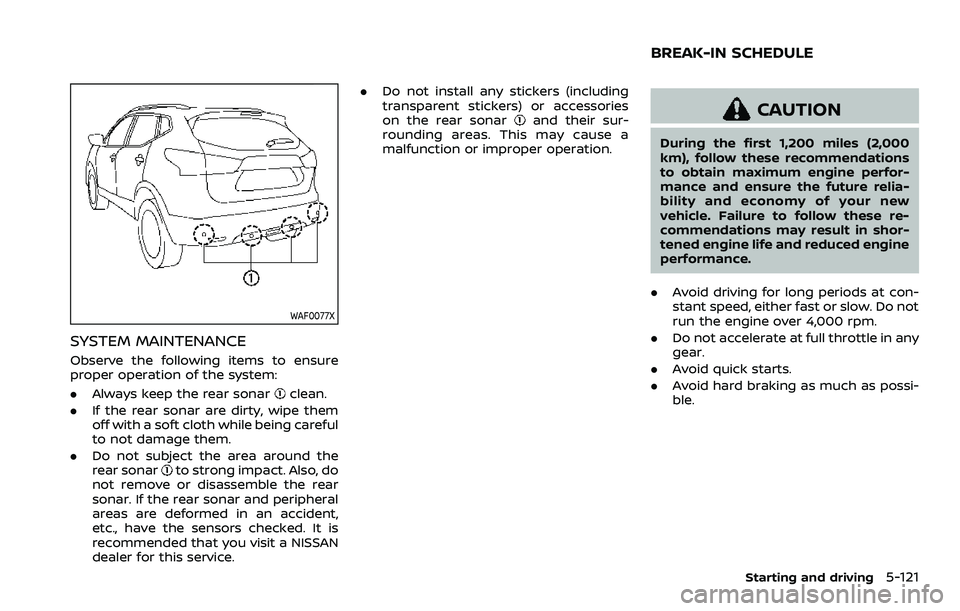
SYSTEM MAINTENANCE
Observe the following items to ensure
proper operation of the system:
.Always keep the rear sonar
clean.
. If the rear sonar are dirty, wipe them
off with a soft cloth while being careful
to not damage them.
. Do not subject the area around the
rear sonar
to strong impact. Also, do
not remove or disassemble the rear
sonar. If the rear sonar and peripheral
areas are deformed in an accident,
etc., have the sensors checked. It is
recommended that you visit a NISSAN
dealer for this service. .
Do not install any stickers (including
transparent stickers) or accessories
on the rear sonar
and their sur-
rounding areas. This may cause a
malfunction or improper operation.CAUTION
During the first 1,200 miles (2,000
km), follow these recommendations
to obtain maximum engine perfor-
mance and ensure the future relia-
bility and economy of your new
vehicle. Failure to follow these re-
commendations may result in shor-
tened engine life and reduced engine
performance.
. Avoid driving for long periods at con-
stant speed, either fast or slow. Do not
run the engine over 4,000 rpm.
. Do not accelerate at full throttle in any
gear.
. Avoid quick starts.
. Avoid hard braking as much as possi-
ble.
Starting and driving5-121
BREAK-IN SCHEDULE
Page 370 of 508

5-130Starting and driving
BRAKE ASSIST
When the force applied to the brake pedal
exceeds a certain level, the Brake Assist is
activated generating greater braking
force than a conventional brake booster
even with light pedal force.
WARNING
The Brake Assist is only an aid to
assist braking operation and is not a
collision warning or avoidance de-
vice. It is the driver’s responsibility to
stay alert, drive safely and be in
control of the vehicle at all times.
ANTI-LOCK BRAKING SYSTEM (ABS)
WARNING
.The Anti-lock Braking System
(ABS) is a sophisticated device,
but it cannot prevent accidents
resulting from careless or dan-
gerous driving techniques. It can
help maintain vehicle control dur-
ing braking on slippery surfaces.
Remember that stopping dis-
tances on slippery surfaces will
be longer than on normal sur- faces even with ABS. Stopping
distances may also be longer on
rough, gravel or snow covered
roads, or if you are using tire
chains. Always maintain a safe
distance from the vehicle in front
of you. Ultimately, the driver is
responsible for safety.
. Tire type and condition may also
affect braking effectiveness.
— When replacing tires, install
the specified size of tires on
all four wheels.
— When installing a spare tire (if so equipped), make sure that
it is the proper size and type
as specified on the Tire and
Loading Information label.
See “Tire and Loading Infor-
mation label” (P.10-10) of this
manual.
— For detailed information, see “Wheels and tires” (P.8-29) of
this manual.
The Anti-lock Braking System (ABS) con-
trols the brakes so the wheels do not lock
during hard braking or when braking on
slippery surfaces. The system detects the
rotation speed at each wheel and varies
the brake fluid pressure to prevent each wheel from locking and sliding. By pre-
venting each wheel from locking, the
system helps the driver maintain steering
control and helps to minimize swerving
and spinning on slippery surfaces.
Using the system
Depress the brake pedal and hold it down.
Depress the brake pedal with firm steady
pressure, but do not pump the brakes.
The ABS will operate to prevent the
wheels from locking up. Steer the vehicle
to avoid obstacles.
WARNING
Do not pump the brake pedal. Doing
so may result in increased stopping
distances.
Self-test feature
The ABS includes electronic sensors, elec-
tric pumps, hydraulic solenoids and a
computer. The computer has a built-in
diagnostic feature that tests the system
each time you start the engine and move
the vehicle at a low speed in forward or
reverse. When the self-test occurs, you
may hear a “clunk” noise and/or feel a
pulsation in the brake pedal. This is
normal and does not indicate a malfunc-
BRAKE ASSIST
Page 371 of 508
tion. If the computer senses a malfunc-
tion, it switches the ABS off and illumi-
nates the ABS warning light on the
instrument panel. The brake system then
operates normally, but without anti-lock
assistance.
If the ABS warning light illuminates during
the self-test or while driving, have the
vehicle checked. It is recommended you
visit a NISSAN dealer for this service.
Normal operation
The ABS operates at speeds above 3 to 6
MPH (5 to 10 km/h). The speed varies
according to road conditions.
When the ABS senses that one or more
wheels are close to locking up, the
actuator rapidly applies and releases
hydraulic pressure. This action is similar
to pumping the brakes very quickly. You
may feel a pulsation in the brake pedal
and hear a noise from under the hood or
feel a vibration from the actuator when it
is operating. This is normal and indicates
that the ABS is operating properly. How-
ever, the pulsation may indicate that road
conditions are hazardous and extra care
is required while driving.The Vehicle Dynamic Control (VDC) sys-
tem uses various sensors to monitor
driver inputs and vehicle motion. Under
certain driving conditions, the VDC sys-
tem helps to perform the following func-
tions.
.
Controls brake pressure to reduce
wheel slip on one slipping drive wheel
so power is transferred to a non
slipping drive wheel on the same axle.
. Controls brake pressure and engine
output to reduce drive wheel slip
based on vehicle speed (traction con-
trol function).
. Controls brake pressure at individual
wheels and engine output to help the
driver maintain control of the vehicle
in the following conditions:
— understeer (vehicle tends to not
follow the steered path despite
increased steering input)
— oversteer (vehicle tends to spin due to certain road or driving condi-
tions).
The VDC system can help the driver to
maintain control of the vehicle, but it
cannot prevent loss of vehicle control in
all driving situations.
When the VDC system operates, the VDC
warning light
in the instrument panel
flashes so note the following: .
The road may be slippery or the
system may determine some action
is required to help keep the vehicle on
the steered path.
. You may feel a pulsation in the brake
pedal and hear a noise or vibration
from under the hood. This is normal
and indicates that the VDC system is
working properly.
. Adjust your speed and driving to the
road conditions.
If a malfunction occurs in the system, the
VDC warning light
illuminates in the
instrument panel. The VDC system auto-
matically turns off.
The VDC OFF switch is used to turn off the
VDC system. The VDC off indicator
illuminates to indicate the VDC system is
off. When the VDC switch is used to turn
off the system, the VDC system still
operates to prevent one drive wheel from
slipping by transferring power to a non
slipping drive wheel. The VDC warning
light
flashes if this occurs. All other
VDC functions are off, and the VDC
warning light
will not flash. The VDC
system is automatically reset to on when
the ignition switch is placed in the off
position then back to the on position.
See “Vehicle Dynamic Control (VDC) warn-
ing light” (P.2-17) and “Vehicle Dynamic
Control (VDC) off indicator light” (P.2-17).
Starting and driving5-131
VEHICLE DYNAMIC CONTROL (VDC) SYSTEM
Page 374 of 508
5-134Starting and driving
scenes).
INTELLIGENT ENGINE BRAKE (Con-
tinuously Variable Transmission
(CVT) models)
The Intelligent Engine Brake function
adds subtle deceleration by controlling
CVT gear ratio, depending on the corner-
ing condition calculated from driver’s
steering input and plural sensors. This
benefit to easier traceability and less
workload of adjusting speed with braking
at corners.
The Intelligent Engine Brake also adds
subtle deceleration with gear ratio con-
trol according to driver’s brake pedal
operation.
The Intelligent Engine Brake can be set to
ON (enabled) or OFF (disabled) through
the Vehicle Information Display “Settings”
page. See “Vehicle information display”
(P.2-19) for more information.
JVS0403X
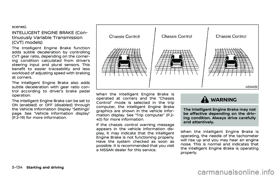
When the Intelligent Engine Brake is
operated at corners and the “Chassis
Control” mode is selected in the trip
computer, the Intelligent Engine Brake
graphics are shown in the vehicle infor-
mation display. See “Trip computer” (P.2-
40) for more information.
If the chassis control warning message
appears in the vehicle information dis-
play, it may indicate that the Intelligent
Engine Brake is not functioning properly.
Have the system checked as soon as
possible. It is recommended that you visit
a NISSAN dealer for this service.
WARNING
The Intelligent Engine Brake may not
be effective depending on the driv-
ing condition. Always drive carefully
and attentively.
When the Intelligent Engine Brake is
operating, the needle of the tachometer
will rise up and you may hear an engine
noise. This is normal and indicates that
the Intelligent Engine Brake is operating
properly.
Page 377 of 508
other maneuvers. Always look
around and check that it is safe
to do so before parking.
. Read and understand the limita-
tions of the RSS as contained in
this section. The colors of the
sonar indicator and the distance
guide lines in the rear view in-
dicate different distances to the
object.
. Inclement weather or ultrasonic
sources such as an automatic car
wash, a truck’s compressed-air
brakes or a pneumatic drill may
affect the function of the system;
this may include reduced perfor-
mance or a false activation.
. The RSS is designed as an aid to
the driver in detecting large sta-
tionary objects to help avoid da-
maging the vehicle.
. The RSS is not designed to pre-
vent contact with small or mov-
ing objects. Always move slowly.
The system will not detect small
objects below the bumper, and
may not detect objects close to
the bumper or on the ground.
. The RSS may not detect the
following objects: fluffy objects
such as snow, cloth, cotton, glass, wool, etc.; thin objects such as
rope, wire and chain, etc.; or
wedge-shaped objects.
. The RSS detects the distance
between the vehicle and the ob-
stacle by detecting the sound
wave reflected from the surface
of an obstacle. When there is a
sound such as horn, or an ultra-
sonic source (such as sonar of
other vehicles) around the vehi-
cle, the sonar may not detect
objects properly.
If your vehicle sustains damage to the
bumper fascia, leaving it misaligned or
bent, the sensing zone may be altered
causing inaccurate measurement of ob-
stacles or false alarms.
CAUTION
. Excessive noise (such as audio
system volume or an open vehi-
cle window) will interfere with the
tone and it may not be heard.
. Keep the sonar sensors (located
on the rear bumper fascia) free
from snow, ice and large accu-
mulations of dirt. Do not clean the
sensors with sharp objects. If the sensors are covered, the accuracy
of the sonar function will be
diminished.
SYSTEM OPERATION
The system informs with a visual and
audible alert of rear obstacles when the
shift lever is in the R (Reverse) position.
Range Rear sonar
Sound Display
P (Park) B C
R (Reverse) O O
N (Neutral) B C
D (Drive) B C
O = Display / Beep when detect
C = Display on camera view
B = No display and beep
The system is deactivated at speeds
above 6 MPH (10 km/h). It is reactivated
at lower speeds.
The intermittent tone will stop after 3
seconds when an obstacle is detected by
only the corner sensor and the distance
does not change. The tone will stop when
the obstacle gets away from the vehicle.
When the object is detected, the indicator
(green) appears and blinks and the tone
sounds intermittently. When the vehicle
moves closer to the object, the color of
Starting and driving5-137
Page 379 of 508
WAF0076X
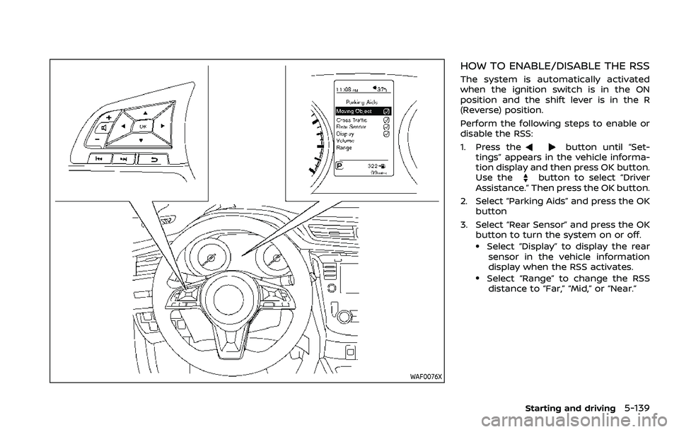
HOW TO ENABLE/DISABLE THE RSS
The system is automatically activated
when the ignition switch is in the ON
position and the shift lever is in the R
(Reverse) position.
Perform the following steps to enable or
disable the RSS:
1. Press the
button until “Set-
tings” appears in the vehicle informa-
tion display and then press OK button.
Use the
button to select “Driver
Assistance.” Then press the OK button.
2. Select “Parking Aids” and press the OK button
3. Select “Rear Sensor” and press the OK button to turn the system on or off.
.Select “Display” to display the rear
sensor in the vehicle information
display when the RSS activates.
.Select “Range” to change the RSSdistance to “Far,” “Mid,” or “Near.”
Starting and driving5-139