NISSAN QUEST 1996 V40 / 1.G Owners Manual
Manufacturer: NISSAN, Model Year: 1996, Model line: QUEST, Model: NISSAN QUEST 1996 V40 / 1.GPages: 235, PDF Size: 1.77 MB
Page 151 of 235
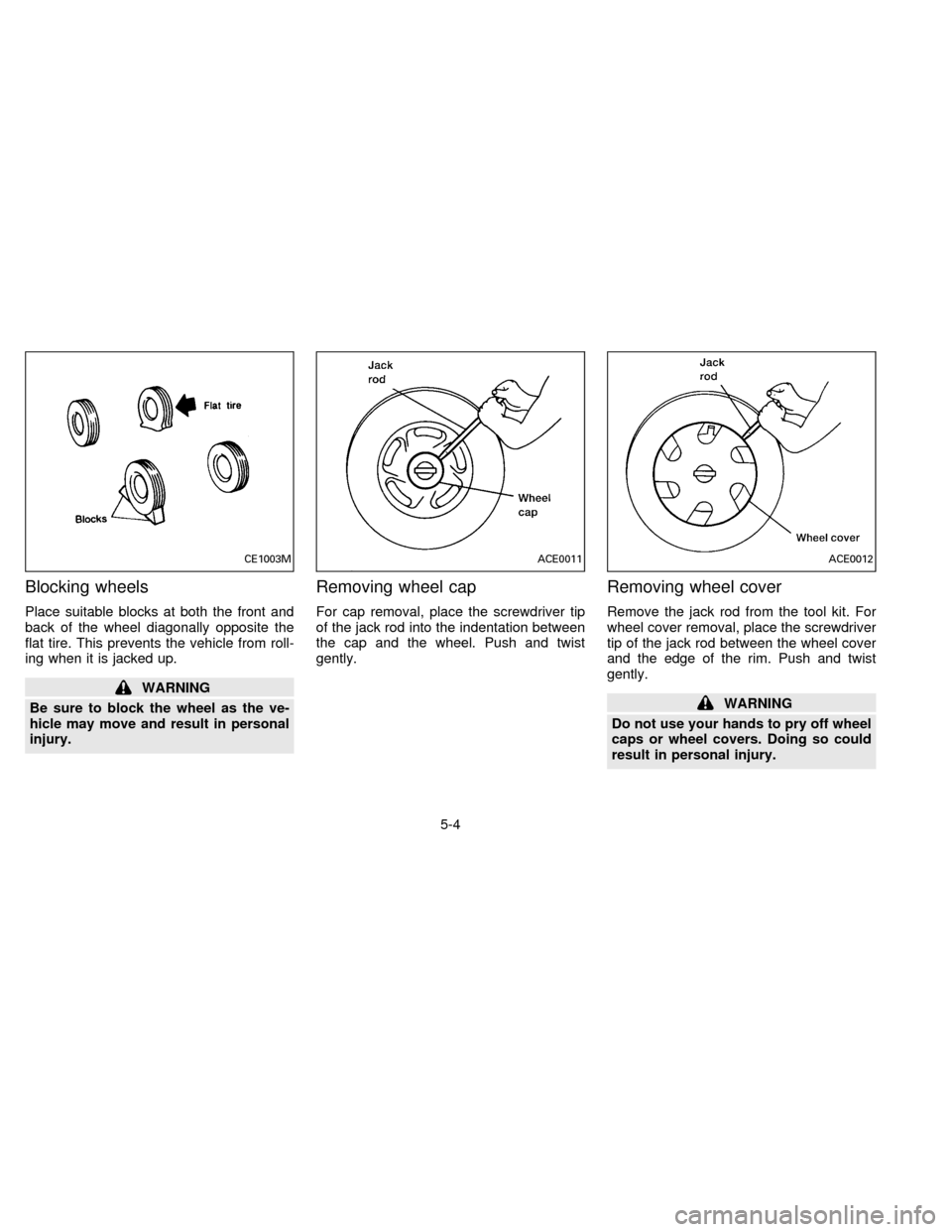
Blocking wheels
Place suitable blocks at both the front and
back of the wheel diagonally opposite the
flat tire. This prevents the vehicle from roll-
ing when it is jacked up.
WARNING
Be sure to block the wheel as the ve-
hicle may move and result in personal
injury.
Removing wheel cap
For cap removal, place the screwdriver tip
of the jack rod into the indentation between
the cap and the wheel. Push and twist
gently.
Removing wheel cover
Remove the jack rod from the tool kit. For
wheel cover removal, place the screwdriver
tip of the jack rod between the wheel cover
and the edge of the rim. Push and twist
gently.
WARNING
Do not use your hands to pry off wheel
caps or wheel covers. Doing so could
result in personal injury.
CE1003MACE0011ACE0012
5-4
ZX
Page 152 of 235
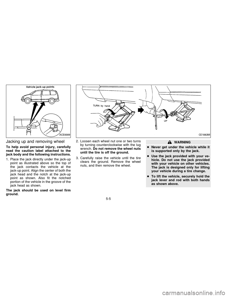
Jacking up and removing wheel
To help avoid personal injury, carefully
read the caution label attached to the
jack body and the following instructions.
1. Place the jack directly under the jack-up
point as illustrated above so the top of
the jack contacts the vehicle at the
jack-up point. Align the center of both the
jack head and the notch at the jack-up
point as shown. Also fit the notched
portion of the vehicle in the groove of the
jack head as shown.
The jack should be used on level firm
ground.2. Loosen each wheel nut one or two turns
by turning counterclockwise with the lug
wrench.Do not remove the wheel nuts
until the tire is off the ground.
3. Carefully raise the vehicle until the tire
clears the ground. Remove the wheel
nuts, and then remove the wheel.
WARNING
cNever get under the vehicle while it
is supported only by the jack.
cUse the jack provided with your ve-
hicle. Do not use the jack provided
with your vehicle on other vehicles.
The jack is designed only for lifting
your vehicle during a tire change.
cTo lift the vehicle, securely hold the
jack lever and rod with both hands
as shown above.
ACE0009CE1063M
5-5
ZX
Page 153 of 235
cUse the correct jack-up points; never
use any other part of the vehicle for
jack support.
cNever jack up the vehicle more than
necessary.
cNever use blocks on or under the
jack.
cDo not start or run engine while
vehicle is on the jack as it may cause
the vehicle to move.
cDo not allow passengers to stay in
the vehicle while it is on the jack.
cDo not raise the vehicle using a
bumper jack.
Installing wheel
The T-type spare tire is designed for
emergency use. See specific instruc-
tions under the heading ``Wheels and
tires'' in the ``Do-it-yourself operations''
section.
1. Clean any mud or dirt from the surface
between the wheel and hub.
2. Carefully put the wheel on and tighten
the lug nuts finger tight.
3. With the lug wrench, tighten lug nuts
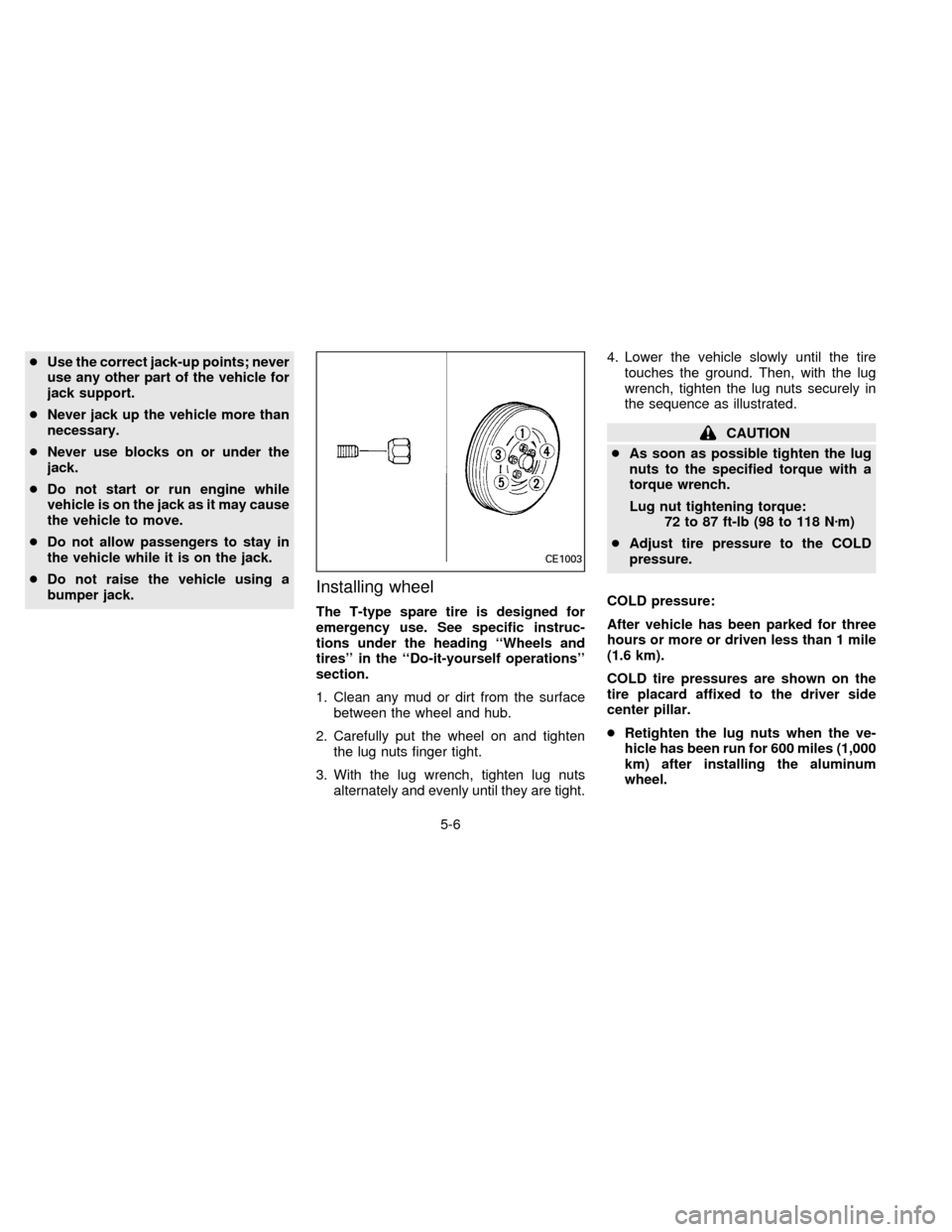
alternately and evenly until they are tight.4. Lower the vehicle slowly until the tire
touches the ground. Then, with the lug
wrench, tighten the lug nuts securely in
the sequence as illustrated.
CAUTION
cAs soon as possible tighten the lug
nuts to the specified torque with a
torque wrench.
Lug nut tightening torque:
72 to 87 ft-lb (98 to 118 Nzm)
cAdjust tire pressure to the COLD
pressure.
COLD pressure:
After vehicle has been parked for three
hours or more or driven less than 1 mile
(1.6 km).
COLD tire pressures are shown on the
tire placard affixed to the driver side
center pillar.
cRetighten the lug nuts when the ve-
hicle has been run for 600 miles (1,000
km) after installing the aluminum
wheel.
CE1003
5-6
ZX
Page 154 of 235
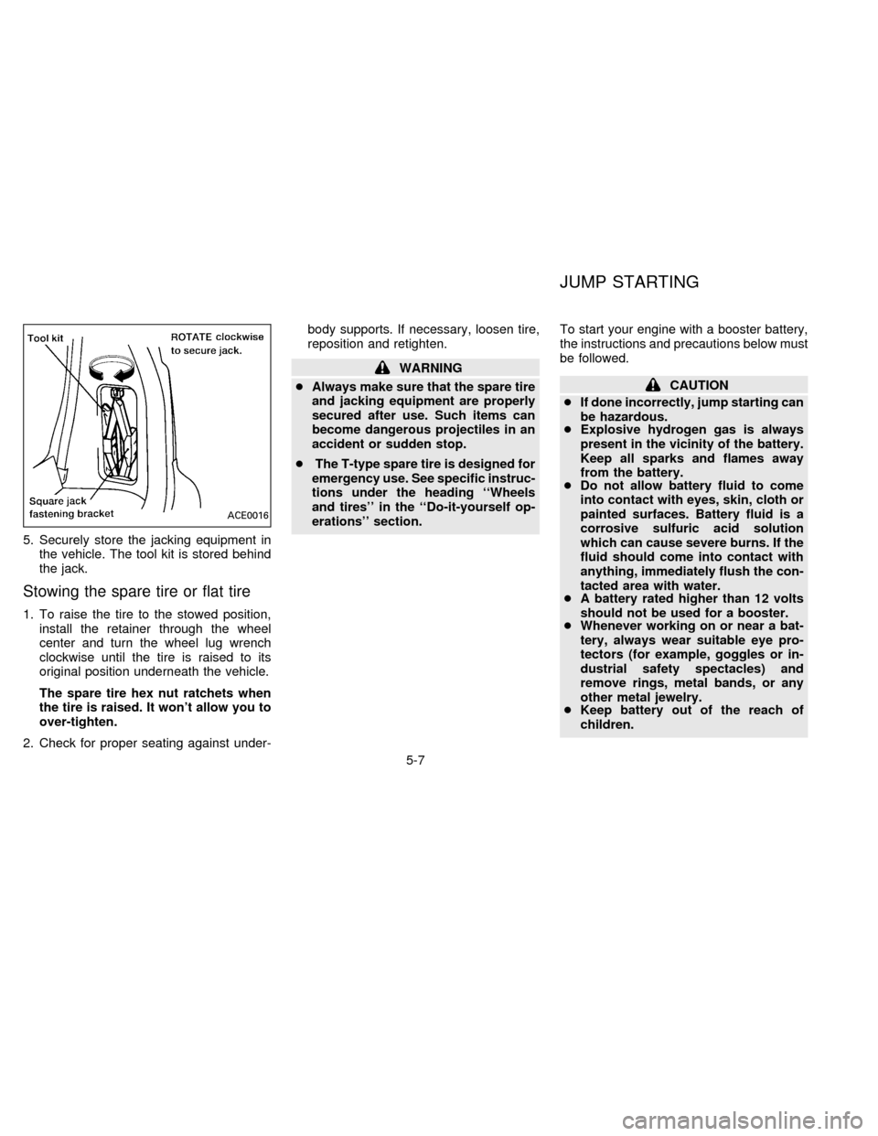
5. Securely store the jacking equipment in
the vehicle. The tool kit is stored behind
the jack.
Stowing the spare tire or flat tire
1. To raise the tire to the stowed position,
install the retainer through the wheel
center and turn the wheel lug wrench
clockwise until the tire is raised to its
original position underneath the vehicle.
The spare tire hex nut ratchets when
the tire is raised. It won't allow you to
over-tighten.
2. Check for proper seating against under-body supports. If necessary, loosen tire,
reposition and retighten.
WARNING
cAlways make sure that the spare tire
and jacking equipment are properly
secured after use. Such items can
become dangerous projectiles in an
accident or sudden stop.
cThe T-type spare tire is designed for
emergency use. See specific instruc-
tions under the heading ``Wheels
and tires'' in the ``Do-it-yourself op-
erations'' section.To start your engine with a booster battery,
the instructions and precautions below must
be followed.
CAUTION
cIf done incorrectly, jump starting can
be hazardous.
cExplosive hydrogen gas is always
present in the vicinity of the battery.
Keep all sparks and flames away
from the battery.
cDo not allow battery fluid to come
into contact with eyes, skin, cloth or
painted surfaces. Battery fluid is a
corrosive sulfuric acid solution
which can cause severe burns. If the
fluid should come into contact with
anything, immediately flush the con-
tacted area with water.
cA battery rated higher than 12 volts
should not be used for a booster.
cWhenever working on or near a bat-
tery, always wear suitable eye pro-
tectors (for example, goggles or in-
dustrial safety spectacles) and
remove rings, metal bands, or any
other metal jewelry.
cKeep battery out of the reach of
children.
ACE0016
JUMP STARTING
5-7
ZX
Page 155 of 235
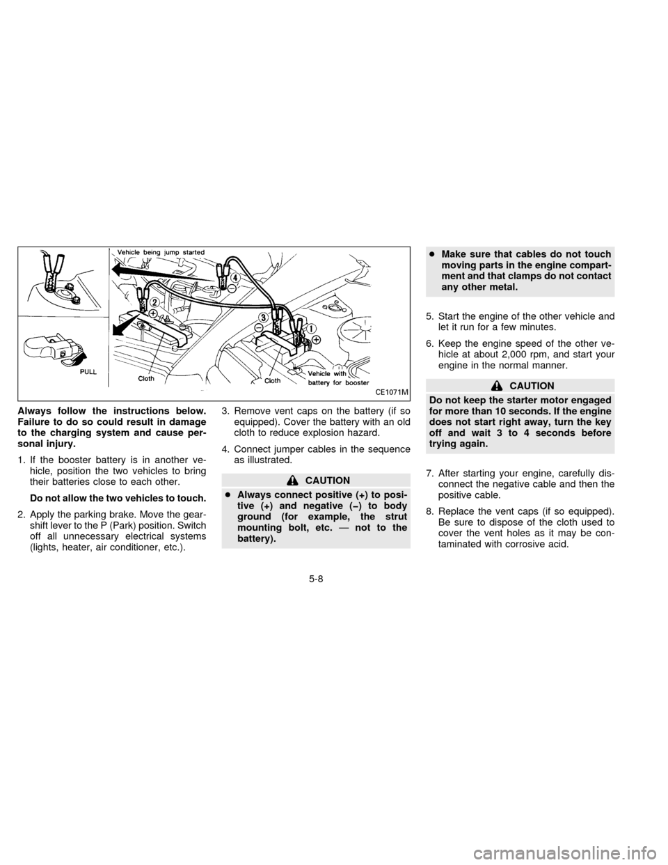
Always follow the instructions below.
Failure to do so could result in damage
to the charging system and cause per-
sonal injury.
1. If the booster battery is in another ve-
hicle, position the two vehicles to bring
their batteries close to each other.
Do not allow the two vehicles to touch.
2. Apply the parking brake. Move the gear-
shift lever to the P (Park) position. Switch
off all unnecessary electrical systems
(lights, heater, air conditioner, etc.).3. Remove vent caps on the battery (if so
equipped). Cover the battery with an old
cloth to reduce explosion hazard.
4. Connect jumper cables in the sequence
as illustrated.
CAUTION
cAlways connect positive (+) to posi-
tive (+) and negative (þ) to body
ground (for example, the strut
mounting bolt, etc.Ðnot to the
battery).cMake sure that cables do not touch
moving parts in the engine compart-
ment and that clamps do not contact
any other metal.
5. Start the engine of the other vehicle and
let it run for a few minutes.
6. Keep the engine speed of the other ve-
hicle at about 2,000 rpm, and start your
engine in the normal manner.
CAUTION
Do not keep the starter motor engaged
for more than 10 seconds. If the engine
does not start right away, turn the key
off and wait 3 to 4 seconds before
trying again.
7. After starting your engine, carefully dis-
connect the negative cable and then the
positive cable.
8. Replace the vent caps (if so equipped).
Be sure to dispose of the cloth used to
cover the vent holes as it may be con-
taminated with corrosive acid.CE1071M
5-8
ZX
Page 156 of 235
CAUTION
Automatic transmission models cannot
be push started. This may cause trans-
mission damage.If your vehicle is overheating (indicated by
an extremely high temperature gauge read-
ing), or if you feel a lack of engine power,
detect abnormal noise, etc., take the follow-
ing steps:
WARNING
To avoid the danger of being scalded,
never remove the radiator cap while the
engine is still hot. When the radiator
cap is removed, pressurized hot water
will spurt out, possibly causing serious
injury.
1. Move the vehicle safely off the road,
apply the parking brake and move the
gearshift lever to the P (Park) position.
Do not stop the engine.
2. Turn off the air conditioner switch. Open
all the windows, move the temperature
control dial to warm and fan control knob
to 4.
3. Get out of the vehicle. Look and listen for
steam or coolant escaping from the ra-
diator before opening the hood. Wait until
no steam or coolant can be seen before
proceeding.4. Open the hood.
WARNING
If steam or water is coming from the
engine, stand clear to prevent getting
burned.
5. If engine overheating is caused by climb-
ing a long hill on a hot day, run the engine
at a fast idle (approximately 1,500 rpm)
until the temperature gauge indication
returns to normal.
6. Visually check drive belts for damage or
looseness. Also check to make sure the
cooling fan is running. The radiator hoses
and radiator should not leak water.
WARNING
Be careful not to allow your hands, hair
or clothing to come into contact with,
or to get caught in, the running fan,
belts, or motor fan.
The fan motor may start at any time
when the coolant temperature is high.
If coolant is leaking, the water pump
belt is missing or loose, or the cooling
fan does not run, stop the engine.
IF YOUR VEHICLE
OVERHEATS
5-9
ZX
Page 157 of 235
7. After the engine cools down completely,
check the coolant level in the reservoir
tank with the engine running. Add coolant
to the reservoir tank if necessary. Have
your vehicle repaired at the nearest NIS-
SAN dealer.
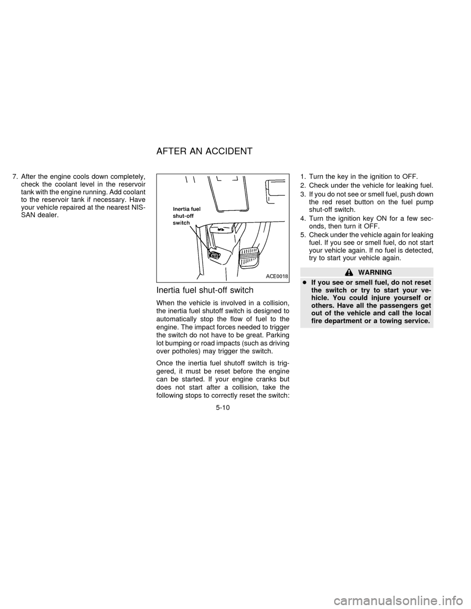
Inertia fuel shut-off switch
When the vehicle is involved in a collision,
the inertia fuel shutoff switch is designed to
automatically stop the flow of fuel to the
engine. The impact forces needed to trigger
the switch do not have to be great. Parking
lot bumping or road impacts (such as driving
over potholes) may trigger the switch.
Once the inertia fuel shutoff switch is trig-
gered, it must be reset before the engine
can be started. If your engine cranks but
does not start after a collision, take the
following stops to correctly reset the switch:1. Turn the key in the ignition to OFF.
2. Check under the vehicle for leaking fuel.
3. If you do not see or smell fuel, push down
the red reset button on the fuel pump
shut-off switch.
4. Turn the ignition key ON for a few sec-
onds, then turn it OFF.
5. Check under the vehicle again for leaking
fuel. If you see or smell fuel, do not start
your vehicle again. If no fuel is detected,
try to start your vehicle again.
WARNING
cIf you see or smell fuel, do not reset
the switch or try to start your ve-
hicle. You could injure yourself or
others. Have all the passengers get
out of the vehicle and call the local
fire department or a towing service.ACE0018
AFTER AN ACCIDENT
5-10
ZX
Page 158 of 235
When towing your vehicle, all state (provin-
cial in Canada) and local regulations for
towing must be followed. Incorrect towing
equipment could damage your vehicle.
Towing instructions are available from your
NISSAN dealer. Local service operators are
generally familiar with the applicable laws
and procedures for towing. To assure
proper towing and to prevent accidental
damage to your vehicle, NISSAN recom-
mends that you have a service operator tow
your vehicle. It is advisable to have the
service operator carefully read the following
precautions.
CAUTION
cWhen towing, make sure that the
transmission, axles, steering system
and powertrain are in working con-
dition. If any unit is damaged, dollies
must be used.
cNever use a tow bar that attaches to
the bumper when you tow your ve-
hicle. It may damage the bumper and
cause damage to the transmission.cWhen towing with the front wheels
on dollies:
Turn the ignition key to the OFF
position and secure the steering
wheel in a straight-ahead position
with a rope or similar device. Never
place the ignition key in the LOCK
position. This will result in damage
to the steering lock mechanism.
Move the gearshift lever to the N
(Neutral) position.
cWhen towing with the rear wheels on
the ground, release the parking
brake.
cAttach safety chains for all towing.
TOW TRUCK TOWING
5-11
ZX
Page 159 of 235

NISSAN recommends that your vehicle be
towed with the driving (front) wheels off the
ground as illustrated.
cSpeed: Below 60 MPH (97 km/h)
c
Distance: Less than 500 miles (800 km)
ACE0560
5-12
ZX
Page 160 of 235
Towing the vehicle with rear wheels
raised (with front wheels on the
ground)
CAUTION
Never tow the vehicle with the rear
wheels raised (with the front wheels on
the ground)as this may cause serious
and expensive damage to the transmis-
sion. If it is necessary to tow the vehicle
with the rear wheels raised, always use
towing dollies under the front wheels.
If you have to tow the vehicle with
four wheels on ground
Observe the following restricted towing
speeds and distances.
cSpeed: Below 30 MPH (50 km/h)
cDistance: Less than 40 miles (65 km)
CAUTION
Never tow the vehicle from the rear (i.e.,
backward) with four wheels on the
ground as this may cause serious and
expensive damage to the transmission.cDo not tow with a sling type truck,
either from the front or the rear. It
may cause body damage.
cNever utilize the rear tie down brack-
ets or slots to tow another vehicle as
this may cause body damage.
VEHICLE RECOVERY (Freeing a
stuck vehicle)
cTow chains or cables must only be at-
tached to the main structual members of
the vehicle.
cPulling devices should be routed so they
do not touch any part of the suspension,
steering, brake or cooling systems.
cAlways pull the cable straight out from
the front or rear of the vehicle. Never pull
on the vehicle at a sideways angle.
cPulling devices such as ropes or canvas
straps are not recommended for use in
vehicle towing or recovery.
5-13
ZX