wheel NISSAN QUEST 1998 V40 / 1.G Owners Manual
[x] Cancel search | Manufacturer: NISSAN, Model Year: 1998, Model line: QUEST, Model: NISSAN QUEST 1998 V40 / 1.GPages: 260, PDF Size: 2.18 MB
Page 25 of 260

This Supplemental Restraint System de-
scription contains important information
concerning the special driver and passen-
ger supplemental air bag. The Supplemen-
tal Restraint System Air Bag can help re-
duce impact force to the driver and to the
front passenger in certain frontal collisions.
The supplemental air bags are designed to
supplementthe crash protection provided
by the seat belts and arenot a substitute
for the seat belts. The seat belts should
always be correctly worn and the driver and
front passenger seated a suitable distance
from the steering wheel and instrument
panel. (See ``Seat belts'' for instructions and
precautions on seat belt usage later in this
section.)
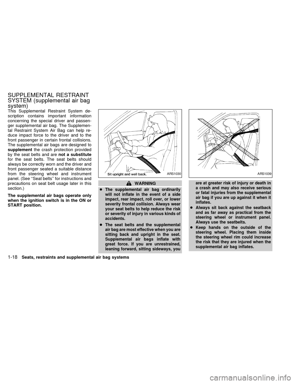
The supplemental air bags operate only
when the ignition switch is in the ON or
START position.
WARNING
c
The supplemental air bag ordinarily
will not inflate in the event of a side
impact, rear impact, roll over, or lower
severity frontal collision. Always wear
your seat belts to help reduce the risk
or severity of injury in various kinds of
accidents.
cThe seat belts and the supplemental
air bag are most effective when you are
sitting back and upright in the seat.
Supplemental air bags inflate with
great force. If you are unrestrained,
leaning forward, sitting sideways, youare at greater risk of injury or death in
a crash and may also receive serious
or fatal injuries from the supplemental
air bag if you are up against it when it
inflates.
cAlways sit back against the seatback
and as far away as practical from the
steering wheel or instrument panel.
Always use the seatbelts.
cKeep hands on the outside of the
steering wheel. Placing them inside
the steering wheel rim could increase
the risk that they are injured when the
supplemental air bag inflates.
ARS1030ARS1039
SUPPLEMENTAL RESTRAINT
SYSTEM (supplemental air bag
system)
1-18Seats, restraints and supplemental air bag systems
ZX
Page 28 of 260

The driver supplemental air bag is located in
the center of the steering wheel; the front
passenger supplemental air bag is mounted in
the dashboard above the glove box.
These systems are designed to meet optional
certification requirements under U.S. regula-
tions. They are also permitted in Canada. The
optional certification allows air bags to be
designed to inflate somewhat less forcefully
than previously.However, all of the infor-
mation, cautions and warnings in this
manual still apply and must be followed.
The supplemental air bag system is designed
to inflate in higher severity frontal collisions,although it may inflate if the forces in another
type of collision are similar to those of a higher
severity frontal impact. It may not inflate in
certain frontal collisions. Vehicle damage (or
lack of it) is not always an indication of proper
supplemental air bag operation.
When the supplemental air bag inflates, a
fairly loud noise may be heard, followed by
the release of smoke. This smoke is not
harmful and does not indicate a fire, but
care should be taken not to unintentionally
inhale it, as it may cause irritation and
choking. Those with a history of a breathing
condition should get fresh air promptly.The supplemental air bags, along with the
use of seat belts, help to cushion the impact
force on the face and chest of the occupant.
They can help save lives and reduce seri-
ous injuries. However, an inflating supple-
mental air bag may cause facial abrasions
or other injuries. Supplemental air bags do
not provide restraint to the lower body.
Seat belts should be correctly worn and the
driver and passenger seated upright as far
away as practical from the steering wheel or
dashboard. Since the supplemental air bag
inflates quickly in order to help protect the
occupant, the force of the supplemental air
bag inflating can increase the risk of injury if
the occupant is too close to or is against the
supplemental air bag module during inflation.
The supplemental air bag deflates quickly
after a collision.The supplemental air
bags operate only when the ignition
switch is in the ON or START position.
APD0846
SUPPLEMENTAL AIR BAG
SYSTEM
Seats, restraints and supplemental air bag systems1-21
ZX
Page 29 of 260

WARNING
cDo not place any objects on the
steering wheel pad or the instrument
panel. Also, do not place any objects
between any occupant and the steer-
ing wheel or instrument panel. Such
objects may become dangerous pro-
jectiles and cause injury if the
supplemental air bag inflates.
cRight after inflation, several supple-
mental air bag system components
will be hot. Do not touch them; you
may severely burn yourself.
cNo unauthorized changes should be
made to any components or wiring
of the supplemental air bag system.
This is to prevent accidental inflation
of the supplemental air bag or dam-
age to the supplemental air bag sys-
tem.
cDo not make unauthorized changes
to your vehicles electrical system,
suspension system or front end
structure. This could affect proper
operation of the supplemental air
bag system.cTampering with the supplemental air
bag system may result in serious
personal injury. Tampering includes
changes to the steering wheel and
the instrument panel assembly by
placing material over the steering
wheel pad and above the instrument
panel, or by installing additional trim
material around the supplemental air
bag system.
cWork around and on the supplemen-
tal air bag system should be done by
an authorized NISSAN dealer. Instal-
lation of electrical equipment should
also be done by an authorized NIS-
SAN dealer. The yellow Supplemen-
tal Restraint System (SRS) wiring
should not be modified or discon-
nected. Unauthorized electrical test
equipment and probing devices
should not be used on the supple-
mental air bag system.
cThe SRS wiring harnesses are cov-
ered with yellow insulation either
just before the harness connectors
or over the complete harness for
easy identification.When selling your vehicle, we request that
you inform the buyer about the supplemental
air bag system and guide the buyer to the
appropriate sections in this Owner's Manual.
1-22Seats, restraints and supplemental air bag systems
ZX
Page 95 of 260

The autolamp system allows the headlights
to be set so they turn on and off automati-
cally. The autolamp system can turn on the
headlights automatically when it is dark,
turn off the headlights when it is light, and
keep the headlights on for up to three
minutes after you turn the key to OFF.
To set the autolamp system:
1. Make sure the headlight switch is in the
OFF position. If the headlight switch is in
the
orposition, the autolamp
system is canceled.
2. Turn the ignition key to ON.3. Use the autolamp switch to activate the
autolamp feature. It is to the left of the
steering wheel.
4. Turn the switch to the right. A slight
detent in the switch indicates it has been
turned past the off position. After the
switch is turned past the detent, the
autolamp automatically turns the lamps
on and off.
Shut-off delay
The length of time the autolamps stay on
after the ignition is turned to OFF depends
on how far the switch is turned to the right.
If the switch is turned all the way to the right,
the headlights stay on about three minutes
after the ignition is turned to OFF. If the
switch is turned only a little way to the right,
the headlights may stay on for less than a
minute.
To turn the autolamp system off, turn the
switch all the way to the left until the detent
is felt.Be sure you do not put anything on top
of the photo sensor located in the top
right side of the instrument panel. The
photo sensor controls the autolamp; if it
is covered, the photo sensor reacts as if
it is dark out and the headlights will
illuminate.
AIC0041AIC0584
AUTOLAMP SWITCH
(if so equipped)
2-14Instruments and controls
ZX
Page 108 of 260

3 Pre-driving checks and adjustments
Key .........................................................................3-2
Door locks ..............................................................3-2
Manual door lock ....................................................3-3
Child safety sliding door lock .................................3-5
Power door lock (if so equipped) ...........................3-6
Multi-remote control system (if so equipped).........3-8
Battery replacement ...............................................3-9
Illuminated entry system ......................................3-10
Hood release ........................................................3-11Rear door lock ......................................................3-12
Cargo net (if so equipped) ...................................3-14
Luggage rack (if so equipped) .............................3-15
Fuel filler lid and cap ............................................3-16
Tilting steering wheel ...........................................3-17
Outside mirror control...........................................3-17
Outside mirrors .....................................................3-18
Inside mirror .........................................................3-18
Vanity mirror .........................................................3-19
ZX
Page 124 of 260

Push the lock lever down and adjust the
steering wheel up or down to the desired
position. Pull the lock lever up firmly to lock
the steering wheel in place.
Gently pull down on the wheel to be sure it
is properly locked.
WARNING
Do not adjust the steering wheel while
driving. You could lose control of your
vehicle and cause an accident.
Electric control type
The outside mirrors operate only when the
ignition switch is in the ACC or ON position.
Move the switch to select the right or left
side mirror, then adjust using the control
lever.
WARNING
Objects viewed in the outside mirror on
the passenger side are closer than they
appear. Be careful when moving to the
right. Using only this mirror couldcause an accident. Use the inside mir-
ror or glance over your shoulder to
properly judge distances to other ob-
jects.
The electric control type outside mirrors can
be heated to defrost, defog, or de-ice for
improved visibility. Press the rear window
defogger switch to activate the heating func-
tion. Press the switch again to deactivate, or
it automatically turns off in approximately 15
minutes.
APD0812APD0808
TILTING STEERING WHEEL OUTSIDE MIRROR CONTROL
Pre-driving checks and adjustments3-17
ZX
Page 128 of 260

4Heater, air conditioner and audio systems
Ventilators ..............................................................4-2
Heater and air conditioner (manual) ......................4-3
Controls ..................................................................4-3
Heater operation ....................................................4-4
Air conditioner operation ........................................4-5
Air flow charts.........................................................4-7
Heater and air conditioner (automatic) (if so
equipped) .............................................................4-10
Automatic operation .............................................4-11
Air control buttons ................................................4-11
Air conditioner and air recirculation .....................4-12
English/metric mode .............................................4-12
Rear seat heater and air conditioner (if so
equipped) .............................................................4-13Controls ................................................................4-13
Audio system ........................................................4-14
AM-FM radio with cassette player .......................4-14
Tuning ..................................................................4-16
Adjusting tone quality ...........................................4-17
Cassette tape operations .....................................4-18
Antenna ................................................................4-20
Compact disc (CD) player (if so equipped) .........4-21
Steering wheel controls ........................................4-23
Rear audio controls ..............................................4-24
CB radio or car phone..........................................4-25
ZX
Page 137 of 260

WARNING
cThe air conditioner cooling function
operates only when the engine is
running.
cDo not leave children, unreliable
adults, or pets alone in your vehicle.
On hot, sunny days, temperatures in
a closed vehicle could quickly be-
come high enough to cause severe
or possibly fatal injuries to people or
animals.cDo not use the recirculation mode
for long periods as it may cause the
interior air to become stale and the
windows to fog up.
cPositioning of the heater and air con-
ditioner controls should not be done
while driving, in order that full atten-
tion may be given to the driving
operation.
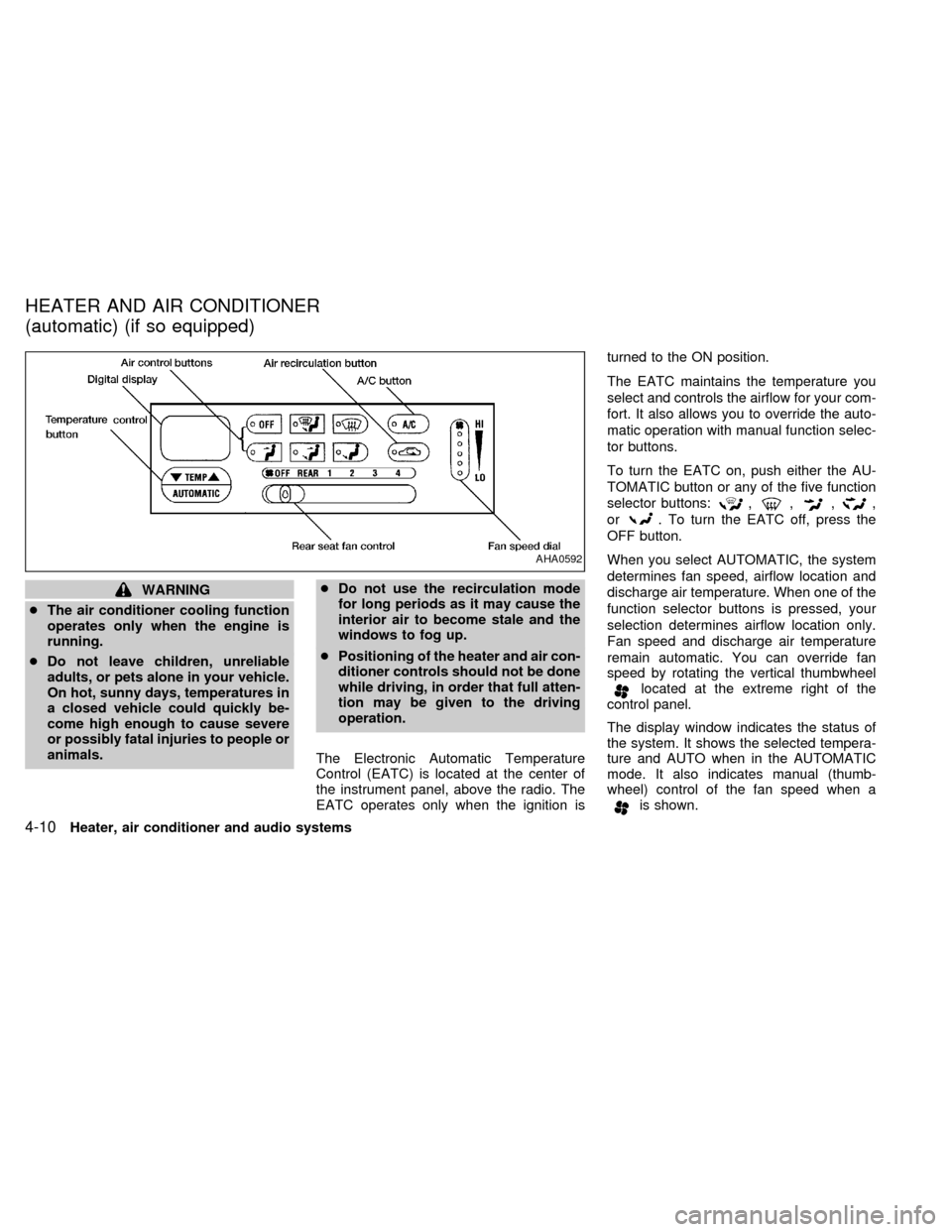
The Electronic Automatic Temperature
Control (EATC) is located at the center of
the instrument panel, above the radio. The
EATC operates only when the ignition isturned to the ON position.
The EATC maintains the temperature you
select and controls the airflow for your com-
fort. It also allows you to override the auto-
matic operation with manual function selec-
tor buttons.
To turn the EATC on, push either the AU-
TOMATIC button or any of the five function
selector buttons:
,,,,
or
. To turn the EATC off, press the
OFF button.
When you select AUTOMATIC, the system
determines fan speed, airflow location and
discharge air temperature. When one of the
function selector buttons is pressed, your
selection determines airflow location only.
Fan speed and discharge air temperature
remain automatic. You can override fan
speed by rotating the vertical thumbwheel
located at the extreme right of the
control panel.
The display window indicates the status of
the system. It shows the selected tempera-
ture and AUTO when in the AUTOMATIC
mode. It also indicates manual (thumb-
wheel) control of the fan speed when a
is shown.
AHA0592
HEATER AND AIR CONDITIONER
(automatic) (if so equipped)
4-10Heater, air conditioner and audio systems
ZX
Page 138 of 260

AUTOMATIC OPERATION
Push the AUTOMATIC button and select the
desired temperature. The selected tempera-
ture and AUTO show in the display window.
The EATC heats or cools to achieve the set
temperature.
When in AUTOMATIC and weather conditions
require heat, air is sent to the floor. However,
a feature is included in the EATC to prevent
blowing cold air to the floor if the engine
coolant is not warm enough to allow heating.
In three or four minutes the fan speed gradu-
ally increases and airflow changes to the floor.
If unique conditions exist, such as window
fogging, the five override buttons allow spe-
cific airflow selection. The thumbwheel al-
lows you to adjust the fan speed to suit your
needs.
Temperature selection
TheTEMPbutton on the left side of
the control panel is for temperature selec-
tion. The
side lowers the set tempera-
ture, and theside raises the set tem-
perature. Press and hold either side of the
button to rapidly change the temperature
setting in one degree increments to either
65ÉF (18ÉC) or 85ÉF (29ÉC). If you wantcontinuous maximum cooling, push the
side of the TEMP button until 60ÉF
(16ÉC) shows in the display window. The
EATC cools at maximum and disregards the
60ÉF (16ÉC) setting until a warmer tempera-
ture is selected. If you want continuous
maximum heating, push the
side of the
TEMP button until 90ÉF (32ÉC) shows in the
display window. The EATC provides maxi-
mum heat regardless of the 90ÉF (32ÉC)
setting until a cooler temperature is se-
lected.
Fan speed and thumbwheel
Your EATC automatically adjusts the fan
speed to the existing conditions. To control
the fan speed yourself, use the thumbwheel
located at the extreme right side of the
EATC control panel. Using the thumbwheel
cancels the automatic fan speed control,
and causes a
to appear in the display
window. Rotate the thumbwheel up for HI
speeds and down for LO speeds.
To return to auto fan control, press the
AUTOMATIC button.
AIR CONTROL BUTTONS
Your EATC has five buttons which allow you
to make special selections. The buttons aregrouped in the middle of the EATC panel
and allow you to determine airflow location.
Pressing any of the air control buttons
changes airflow location only, and does not
affect the ability of the system to control
temperature or fan speed. Return to fully
automatic operation by pushing the AUTO-
MATIC button.
Push this button for airflow to the floor and
windshield at the same time. The
in-
dicator light comes on, and the display
window shows the set temperature.
Press this button to obtain maximum airflow
to the windshield. Adjust the temperature
setting as required for defrosting. The
indicator light comes on, and the
display window shows the set temperature.
When the outside temperature is about
50ÉF (10ÉC) or above, the air is dehumidi-
fied to prevent window fogging.
Push this button to select airflow through
the instrument panel registers. The
Heater, air conditioner and audio systems
4-11
ZX
Page 139 of 260

indicator light comes on, and the
display window shows the set temperature.
The EATC heats the air if the selected
temperature is warmer than the outside air
coming into the vehicle. However, the air is
not cooled regardless of the temperature
setting.
Push this button to get air from the floor and
instrument panel registers at the same time.
The
indicator light comes on and the
display window shows the set temperature.
Depending on the selected temperature, the
air is automatically heated or cooled.
Push this button to direct airflow to the floor.
Theindicator light comes on, and the
display window shows the set temperature.
The air cannot be cooled in the
mode,
only heated.
AIR CONDITIONER AND AIR RE-
CIRCULATION
Activate the air conditioner in any of the
override modes listed above by pressing the
A/C button. The A/C indicator light comeson to verify activation, and cooled air flows
from the vents. Fan speed continues to be
controlled by the EATC unless the fan
speed thumbwheel is used to override.
Press the
button to choose air recir-
culation. In this mode the EATC system
recirculates the air inside the vehicle rather
than drawing air from outside. Use this
mode together with the air conditioner to
rapidly cool the inside of the vehicle, or to
dehumidify the air inside the vehicle.
ENGLISH/METRIC MODE
Switch from English to metric temperature
display by simultaneously pressing the
and A/C buttons and holding the
thumbwheel in upper position (HI) for one
second.
AHA762
4-12Heater, air conditioner and audio systems
ZX