NISSAN QUEST 2000 V41 / 2.G Owners Manual
Manufacturer: NISSAN, Model Year: 2000, Model line: QUEST, Model: NISSAN QUEST 2000 V41 / 2.GPages: 292, PDF Size: 2.48 MB
Page 231 of 292

cRemove the cabin air filter element by
pulling forward on the top surface of the
filter and lifting.4. Install the new cabin air filter element
into the filter retaining frame, ensure that
you insert the three retaining tabs in the
bottom of the filter frame.
5. Install the filter top cover and the four
screws.
6. Feed the windshield washer hose from
the cowl cover through the hole in the
sheet metal.
cEnsure that you fully seat the rubber
grommet into the sheet metal hole.
7. Reconnect the windshield washer hose.8. Position the cowl cover in place.
9. Reinstall the four screw anchors and the
four screws.
10. Close the hood.
11. Install the six screws in the cowl cover.
12. Install the windshield wiper arms.
cPush the wiper arm downward onto the
wiper arm pivot until the small retaining
clip snaps into the locked position.
cLower the wiper arm blade onto the
windshield surface.
ADI1108ADI1109
8-16Do-it-yourself
ZX
Page 232 of 292
CLEANING
If your windshield is not clear after using the
windshield washer or if the wiper blade
chatters when running, wax or other mate-
rial may be on the blade or windshield.
Clean the outside of the windshield with a
washer solution or a mild detergent. Your
windshield is clean if beads do not form
when rinsing with clear water.
Clean the blade by wiping it with a cloth
soaked in a washer solution or a mild deter-
gent. Then, rinse the blade with clear water.
If your windshield is still not clear aftercleaning the blades and using the wipers,
replace the blades.REPLACING
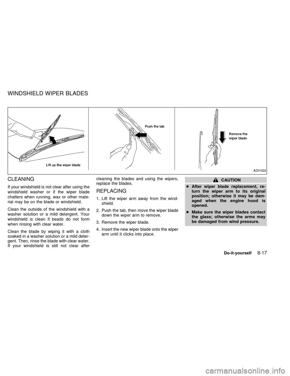
1. Lift the wiper arm away from the wind-
shield.
2. Push the tab, then move the wiper blade
down the wiper arm to remove.
3. Remove the wiper blade.
4. Insert the new wiper blade onto the wiper
arm until it clicks into place.
CAUTION
cAfter wiper blade replacement, re-
turn the wiper arm to its original
position; otherwise it may be dam-
aged when the engine hood is
opened.
cMake sure the wiper blades contact
the glass; otherwise the arms may
be damaged from wind pressure.
ADI1022
WINDSHIELD WIPER BLADES
Do-it-yourself8-17
ZX
Page 233 of 292

Rear window wiper blade
1. Lift the wiper arm away from the wind-
shield.
2. Push the tab, then move the wiper blade
down the wiper arm to remove.
3. Insert a new wiper blade onto the wiper
arm and press down until the blade clicks
into place.
ADI1114
8-18Do-it-yourself
ZX
Page 234 of 292
CHECKING PARKING BRAKE
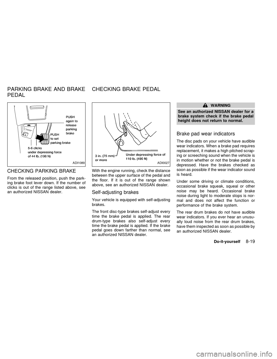
From the released position, push the park-
ing brake foot lever down. If the number of
clicks is out of the range listed above, see
an authorized NISSAN dealer.With the engine running, check the distance
between the upper surface of the pedal and
the floor. If it is out of the range shown
above, see an authorized NISSAN dealer.
Self-adjusting brakes
Your vehicle is equipped with self-adjusting
brakes.
The front disc-type brakes self-adjust every
time the brake pedal is applied. The rear
drum-type brakes also self-adjust every
time the brake pedal is applied. If the brake
pedal goes down farther than normal, see
an authorized NISSAN dealer.
WARNING
See an authorized NISSAN dealer for a
brake system check if the brake pedal
height does not return to normal.
Brake pad wear indicators
The disc pads on your vehicle have audible
wear indicators. When a brake pad requires
replacement, it makes a high pitched scrap-
ing or screeching sound when the vehicle is
in motion whether or not the brake pedal is
depressed. Have the brakes checked as
soon as possible if the wear indicator sound
is heard.
Under some driving or climate conditions,
occasional brake squeak, squeal or other
noise may be heard. Occasional brake
noise during light to moderate stops is nor-
mal and does not affect the function or
performance of the brake system.
The rear drum brakes do not have audible
wear indicators. If you ever hear an unusu-
ally loud noise from the rear drum brakes,
have them inspected as soon as possible by
an authorized NISSAN dealer.
ADI1089ADI0027
PARKING BRAKE AND BRAKE
PEDALCHECKING BRAKE PEDAL
Do-it-yourself8-19
ZX
Page 235 of 292
Proper brake inspection intervals should
be followed.For more information regard-
ing brake inspections, see the appropriate
maintenance schedule information in the
``Maintenance'' section of this manual.
BRAKE BOOSTER
Check the brake booster function as fol-
lows:
1. With the engine off, press and release
the brake pedal several times. When
brake pedal movement (distance of
travel) remains the same from one pedal
application to the next, continue on to the
next step.
2. While depressing the brake pedal, start
the engine. The pedal height should drop
a little.
3. With the brake pedal depressed, turn the
engine off. Keep the pedal depressed for
about 30 seconds; the pedal height
should not change.
4. Run the engine for one minute without
depressing the brake pedal, then turn it
off. Depress the brake pedal several
times. The pedal travel distance will de-
crease gradually with each depressionas the vacuum is released from the
booster.
If the brakes do not operate properly, see an
authorized NISSAN dealer.
ENGINE COMPARTMENT
CAUTION
Never use a fuse of a higher amperage
rating than that specified on the fuse
box cover. This could damage the elec-
trical system or cause a fire.
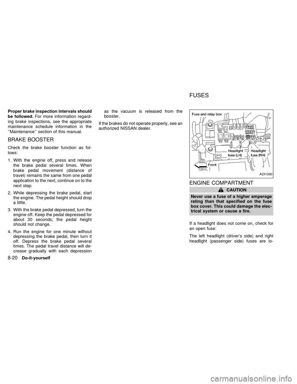
If a headlight does not come on, check for
an open fuse:
The left headlight (driver's side) and right
headlight (passenger side) fuses are lo-
ADI1090
FUSES
8-20Do-it-yourself
ZX
Page 236 of 292
cated in the left-hand fuse box, near the
radiator cap.
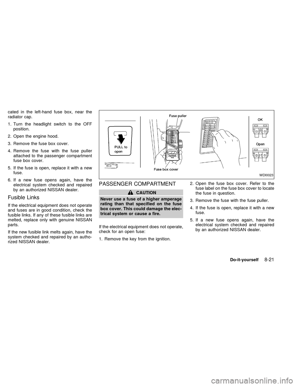
1. Turn the headlight switch to the OFF
position.
2. Open the engine hood.
3. Remove the fuse box cover.
4. Remove the fuse with the fuse puller
attached to the passenger compartment
fuse box cover.
5. If the fuse is open, replace it with a new
fuse.
6. If a new fuse opens again, have the
electrical system checked and repaired
by an authorized NISSAN dealer.
Fusible Links
If the electrical equipment does not operate
and fuses are in good condition, check the
fusible links. If any of these fusible links are
melted, replace only with genuine NISSAN
parts.
If the new fusible link melts again, have the
system checked and repaired by an autho-
rized NISSAN dealer.
PASSENGER COMPARTMENT
CAUTION
Never use a fuse of a higher amperage
rating than that specified on the fuse
box cover. This could damage the elec-
trical system or cause a fire.
If the electrical equipment does not operate,
check for an open fuse:
1. Remove the key from the ignition.2. Open the fuse box cover. Refer to the
fuse label on the fuse box cover to locate
the fuse in question.
3. Remove the fuse with the fuse puller.
4. If the fuse is open, replace it with a new
fuse.
5. If a new fuse opens again, have the
electrical system checked and repaired
by an authorized NISSAN dealer.
WDI0023
Do-it-yourself8-21
ZX
Page 237 of 292

Replace the battery as follows:
1. Open the lid using a coin.
2. Replace the battery with a new one.
Insert the batteries as illustrated above.
Recommended battery: Panasonic
CR2025, 3V or equivalent.
3. Close the lid securely.
4. Press the
button, then thebutton
two or three times to check the multi-
remote controller operation.
If the batteries are removed for any reason
other than replacement, perform step 4.
cAn improperly disposed battery can
hurt the environment. Always conform
to local regulations for battery disposal.
cThe multi-remote controller is water-
resistant; however, if it does get wet,
immediately wipe completely dry.
cThe operational range of the multi-
remote controller extends to approxi-
mately 30 ft (10 m) from the vehicle.
This range may vary with conditions.
FCC Notice:
Changes or modifications not expressly
approved by the manufacturer for com-
pliance could void the user's authority to
operate the equipment.
This device complies with part 15 of the FCC
Rules and RSS-210 of Industry Canada.
Operation is subject to the following two
conditions: (1) This device may not
cause harmful interference, and (2) this
device must accept any interference re-
ceived, including interference that may
cause undesired operation of the device.APD1087
MULTI-REMOTE CONTROLLER
BATTERY REPLACEMENT
8-22Do-it-yourself
ZX
Page 238 of 292
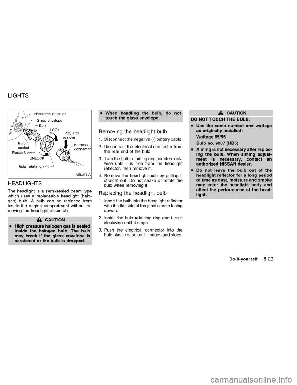
HEADLIGHTS
The headlight is a semi-sealed beam type
which uses a replaceable headlight (halo-
gen) bulb. A bulb can be replaced from
inside the engine compartment without re-
moving the headlight assembly.
CAUTION
cHigh pressure halogen gas is sealed
inside the halogen bulb. The bulb
may break if the glass envelope is
scratched or the bulb is dropped.cWhen handling the bulb, do not
touch the glass envelope.
Removing the headlight bulb
1. Disconnect the negative (-) battery cable.
2. Disconnect the electrical connector from
the rear end of the bulb.
3. Turn the bulb retaining ring counterclock-
wise until it is free from the headlight
reflector, then remove it.
4. Remove the headlight bulb by pulling it
straight out. Do not shake or rotate the
bulb when removing it.
Replacing the headlight bulb
1. Insert the bulb into the headlight reflector
with the flat side of the plastic base facing
upward.
2. Install the bulb retaining ring and turn it
clockwise until it stops.
3. Push the electrical connector into the
bulb plastic base until it snaps and stops.
CAUTION
DO NOT TOUCH THE BULB.
cUse the same number and wattage
as originally installed:
Wattage 65/55
Bulb no. 9007 (HB5)
cAiming is not necessary after replac-
ing the bulb. When aiming adjust-
ment is necessary, contact an
authorized NISSAN dealer.
cDo not leave the bulb out of the
headlight reflector for a long period
of time as dust, moisture and smoke
may enter the headlight body and
affect the performance of the head-
light.
AEL076-A
LIGHTS
Do-it-yourself8-23
ZX
Page 239 of 292

EXTERIOR AND INTERIOR
LIGHTS
Item Wattage (W) Bulb No.
Headlight assembly
High/Low 65/55 9007 (HB5)
Front turn signal light 8.25/27 3157NA
Front combination light:
Front side marker light 3.8 194
Parking/Cornering 8.25/27 3157K
Rear combination light:
Turn signal 27 3156K
Stop/Tail 8.25/27 3157K
Rear side marker light 5 168
Back-up light 27 3156K
License plate light 3.8 194
High-mounted stop light 12.8 912
Interior lights 12 211-2
Personal reading light 10 578
Luggage compartment light 12 211-2
Steplight 3.8 194
Spotlight 10 578
8-24Do-it-yourself
ZX
Page 240 of 292

Replacement procedures
All lights (except for headlights) are either
type A, B, C or D. When replacing a bulb,
first remove the lens and/or cover.
WDI0012
ADI1093
Do-it-yourself8-25
ZX