NISSAN QUEST 2004 V42 / 3.G Owners Manual
Manufacturer: NISSAN, Model Year: 2004, Model line: QUEST, Model: NISSAN QUEST 2004 V42 / 3.GPages: 320, PDF Size: 5.6 MB
Page 271 of 320

Replace the battery in the keyfob as follows:
s1Open the lid using a coin.
s2Remove the battery.
s3Install a new battery with the “+” facing
down.
Recommended battery: Sanyo CR2025 or
equivalent.
s4Close the lid securely.5. Press the LOCK button, then the UNLOCK
button two or three times to check the key-
fob operation.
If the battery is removed for any reason
other than replacement, perform step 5.
cAn improperly disposed battery can
hurt the environment. Always confirm
local regulations for battery disposal.
cThe keyfob is water-resistant; how-
ever, if it does get wet, immediately
wipe completely dry.
cThe operational range of the keyfob
extends to approximately 33 ft (10 m)
from the vehicle. This range may vary
with conditions.
FCC Notice:
Changes or modifications not expressly ap-
proved by the manufacturer for compliance
could void the user’s authority to operate
the equipment.
This device complies with Part 15 of the FCC
Rules and RSS-210 of Industry Canada.
Operation is subject to the following two
conditions: (1) This device may not cause
harmful interference, and (2) this device
must accept any interference received, in-
cluding interference that may cause undes-
ired operation of the device.
LPD0214
KEYFOB BATTERY REPLACEMENT
Maintenance and do-it-yourself8-25
ZREVIEW COPY:Ð2004 Quest(van)
Owners Manual(owners)ÐUSA English(nna)
10/08/03Ðtbrooks
X
Page 272 of 320

HEADLIGHTS
The headlight is a semi-sealed beam type which
uses a replaceable headlight (halogen) bulb. If
replacement is required, see your NISSAN
dealer.
CAUTION
cHigh pressure halogen gas is sealed
inside the halogen bulb. The bulb may
break if the glass envelope is scratched
or the bulb is dropped.
cWhen handling the bulb, do not touch
the glass envelope.
cDO NOT TOUCH THE BULB
cUse the same number and wattage as
originally installed:
Low beam:
Wattage: 51
Bulb no.: 9006*
High beam:
Wattage: 60
Bulb no.: 9005*
*: Always check with the Parts Depart-
ment at a NISSAN dealer for the latest
parts information.cDo not leave the bulb out of the head-
light reflector for a long period of time
as dust, moisture and smoke may enter
the headlight body and affect the per-
formance of the headlight.
cAiming is not necessary after replacing
the bulb. When aiming adjustment is
necessary, contact a NISSAN dealer.
FOG LIGHTS (if so equipped)
Replacing the fog light bulb
CAUTION
cHigh pressure halogen gas is sealed
inside the halogen bulb. The bulb may
break if the glass envelope is scratched
or the bulb is dropped.
cWhen handling the bulb, do not touch
the glass envelope.
cUse the same number and wattage as
originally installed:
Wattage 55 Bulb No. H11*
*: Always check with the Parts Depart-
ment at a NISSAN dealer for the latest
parts information.cDo not leave the bulb out of the fog light
for a long period of time as dust, mois-
ture and smoke may enter the fog light
body and affect the performance of the
fog light.
LIGHTS
8-26Maintenance and do-it-yourself
ZREVIEW COPY:Ð2004 Quest(van)
Owners Manual(owners)ÐUSA English(nna)
10/08/03Ðtbrooks
X
Page 273 of 320

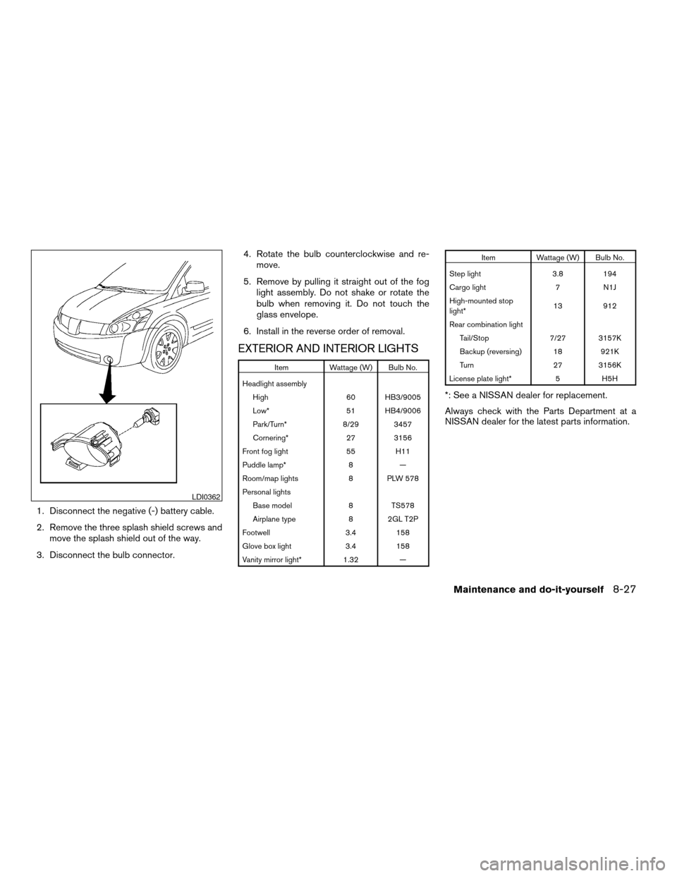
1. Disconnect the negative (-) battery cable.
2. Remove the three splash shield screws and
move the splash shield out of the way.
3. Disconnect the bulb connector.4. Rotate the bulb counterclockwise and re-
move.
5. Remove by pulling it straight out of the fog
light assembly. Do not shake or rotate the
bulb when removing it. Do not touch the
glass envelope.
6. Install in the reverse order of removal.
EXTERIOR AND INTERIOR LIGHTS
Item Wattage (W) Bulb No.
Headlight assembly
High 60 HB3/9005
Low* 51 HB4/9006
Park/Turn* 8/29 3457
Cornering* 27 3156
Front fog light 55 H11
Puddle lamp* 8 —
Room/map lights 8 PLW 578
Personal lights
Base model 8 TS578
Airplane type 8 2GL T2P
Footwell 3.4 158
Glove box light 3.4 158
Vanity mirror light* 1.32 —
Item Wattage (W) Bulb No.
Step light 3.8 194
Cargo light 7 N1J
High-mounted stop
light*13 912
Rear combination light
Tail/Stop 7/27 3157K
Backup (reversing) 18 921K
Turn 27 3156K
License plate light* 5 H5H
*: See a NISSAN dealer for replacement.
Always check with the Parts Department at a
NISSAN dealer for the latest parts information.
LDI0362
Maintenance and do-it-yourself8-27
ZREVIEW COPY:Ð2004 Quest(van)
Owners Manual(owners)ÐUSA English(nna)
10/08/03Ðtbrooks
X
Page 274 of 320

1. Room/map light
2. Front personal lights
3. Step light
4. Puddle lamp
5. High-mount stoplight
6. Cargo light
7. License plate light
8. Rear combination light
9. Headlight assembly
10. Fog light
Replacement procedures
All other lights are either type A, B, C or D. When
replacing a bulb, first remove the lens, lamp
and/or cover.
Indicates bulb removal
Indicates bulb installationLDI0360
WDI0263
8-28Maintenance and do-it-yourself
ZREVIEW COPY:Ð2004 Quest(van)
Owners Manual(owners)ÐUSA English(nna)
10/08/03Ðtbrooks
X
Page 275 of 320

Use a cloths1to protect the housing. Use a cloths1to protect the housing. Use a cloths1to protect the housing.
Room/map lights
LDI0363
Personal lights – Type A
LDI0364
Personal lights – Type B
LDI0365
Maintenance and do-it-yourself8-29
ZREVIEW COPY:Ð2004 Quest(van)
Owners Manual(owners)ÐUSA English(nna)
10/08/03Ðtbrooks
X
Page 276 of 320

Use a cloths1to protect the housing. Use a cloths1to protect the housing.
Step light
LDI0341
Cargo light
LDI0366
Rear combination light
LDI0367
8-30Maintenance and do-it-yourself
ZREVIEW COPY:Ð2004 Quest(van)
Owners Manual(owners)ÐUSA English(nna)
10/08/03Ðtbrooks
X
Page 277 of 320

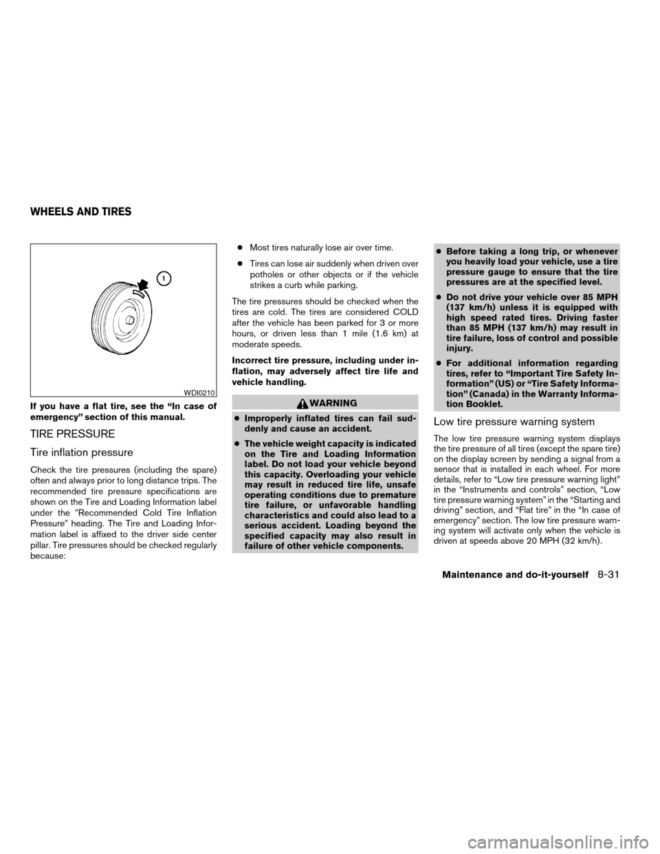
If you have a flat tire, see the “In case of
emergency” section of this manual.
TIRE PRESSURE
Tire inflation pressure
Check the tire pressures (including the spare)
often and always prior to long distance trips. The
recommended tire pressure specifications are
shown on the Tire and Loading Information label
under the9Recommended Cold Tire Inflation
Pressure9heading. The Tire and Loading Infor-
mation label is affixed to the driver side center
pillar. Tire pressures should be checked regularly
because:cMost tires naturally lose air over time.
cTires can lose air suddenly when driven over
potholes or other objects or if the vehicle
strikes a curb while parking.
The tire pressures should be checked when the
tires are cold. The tires are considered COLD
after the vehicle has been parked for 3 or more
hours, or driven less than 1 mile (1.6 km) at
moderate speeds.
Incorrect tire pressure, including under in-
flation, may adversely affect tire life and
vehicle handling.
WARNING
cImproperly inflated tires can fail sud-
denly and cause an accident.
cThe vehicle weight capacity is indicated
on the Tire and Loading Information
label. Do not load your vehicle beyond
this capacity. Overloading your vehicle
may result in reduced tire life, unsafe
operating conditions due to premature
tire failure, or unfavorable handling
characteristics and could also lead to a
serious accident. Loading beyond the
specified capacity may also result in
failure of other vehicle components.cBefore taking a long trip, or whenever
you heavily load your vehicle, use a tire
pressure gauge to ensure that the tire
pressures are at the specified level.
cDo not drive your vehicle over 85 MPH
(137 km/h) unless it is equipped with
high speed rated tires. Driving faster
than 85 MPH (137 km/h) may result in
tire failure, loss of control and possible
injury.
cFor additional information regarding
tires, refer to “Important Tire Safety In-
formation” (US) or “Tire Safety Informa-
tion” (Canada) in the Warranty Informa-
tion Booklet.Low tire pressure warning system
The low tire pressure warning system displays
the tire pressure of all tires (except the spare tire)
on the display screen by sending a signal from a
sensor that is installed in each wheel. For more
details, refer to “Low tire pressure warning light”
in the “Instruments and controls” section, “Low
tire pressure warning system” in the “Starting and
driving” section, and “Flat tire” in the “In case of
emergency” section. The low tire pressure warn-
ing system will activate only when the vehicle is
driven at speeds above 20 MPH (32 km/h) .
WDI0210
WHEELS AND TIRES
Maintenance and do-it-yourself8-31
ZREVIEW COPY:Ð2004 Quest(van)
Owners Manual(owners)ÐUSA English(nna)
10/08/03Ðtbrooks
X
Page 278 of 320

Tire and loading information label (for
US)
s1Seating capacity: The maximum number of
occupants that should be seated in the ve-
hicle.
s2Vehicle load limit: See loading information in
the Technical and consumer information
section.
s3Original tire size: The size of the tires origi-
nally installed on the vehicle at the factory.
s4Recommended cold tire inflation pressure:
Inflate the tires to this pressure when the
tires are cold. Tires are considered COLD
after the vehicle has been parked for 3 or
more hours, or driven less than 1 mile (1.6
km) at moderate speeds. The recommended
cold tire inflation is set by the manufacturer
to provide the best tire wear and vehicle
handling characteristics based on the ve-
hicles GVWR.
s5Tire size – refer to “Tire labeling” later in this
section.
s6ands7. Spare tire size or compact spare tire
size (if so equipped)
Checking tire pressure
1. Remove the valve stem cap from the tire.
2. Press the pressure gauge squarely onto the
valve stem. Do not press too hard or force
the valve stem sideways, or air will escape. If
the hissing of air escaping from the tire is
heard while checking the pressure, reposi-
tion the gauge to eliminate this leakage.
3. Remove the gauge.
4. Read the tire pressure on the gauge stem
and compare to the specification shown on
the Tire and Loading Information label.
LDI0392LDI0393
8-32Maintenance and do-it-yourself
ZREVIEW COPY:Ð2004 Quest(van)
Owners Manual(owners)ÐUSA English(nna)
10/08/03Ðtbrooks
X
Page 279 of 320

5. Add air to the tire as needed. If too much air
is added, press the core of the valve stem
briefly with the tip of the gauge stem to
release pressure. Recheck the pressure and
add or release air as needed.
6. Install the valve stem cap.
7. Check the pressure of all other tires, includ-
ing the spare.
Size Cold Tire Infla-
tion Pressure
Front
Original TireP225/65/R16
P225/60/R17240 kPa, 35 PSI
Rear
Original TireP225/65/R16
P225/60/R17240 kPa, 35 PSI
Spare Tire T135/80D16 420 kPa, 60 PSI
TIRE LABELING
Federal law requires tire manufacturers to place
standardized information on the sidewall of all
tires. This information identifies and describes
the fundamental characteristics of the tire and
also provides the tire identification number (TIN)
for safety standard certification. The TIN can be
used to identify the tire in case of a recall.
WDI0394
Maintenance and do-it-yourself8-33
ZREVIEW COPY:Ð2004 Quest(van)
Owners Manual(owners)ÐUSA English(nna)
10/08/03Ðtbrooks
X
Page 280 of 320

(1) Tire size (example: P215/65R15 95H)
1. P: The9P9indicates the tire is designed for
passenger vehicles.
2. Three-digit number: This number gives the
width in millimeters of the tire from sidewall
edge to sidewall edge.
3. Two-digit number: This number, known as
the aspect ratio, gives the tire’s ratio of
height to width.
4. R: The9R9stands for radial.
5. Two-digit number: This number is the wheel
or rim diameter in inches.6. Two- or three-digit number: This number is
the tire’s load index. It is a measurement of
how much weight each tire can support. You
may not find this information on all tires be-
cause it is not required by law.
7. Tire speed rating. You should not drive the
vehicle faster than the tire speed rating.
WDI0395
8-34Maintenance and do-it-yourself
ZREVIEW COPY:Ð2004 Quest(van)
Owners Manual(owners)ÐUSA English(nna)
10/08/03Ðtbrooks
X